

Page 1
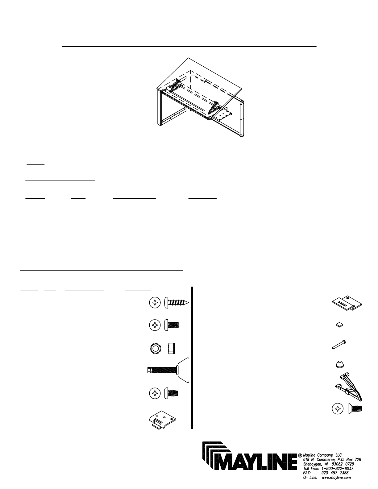
(1)
ASSEMBLY INSTRUCTIONS
CS
CATALOG No:
C36TR
C42TR
C48TR
NOTE: Please count and inspect all pieces before disposing of any carton or packing materials.
COMPONENTS:
REF. # QTY. DESCRIPTION PART No.
1 1 WORK SURFACE CALL~~**
2 1 MODESTY PANEL CALL~~**
3 2 LEG ASSEMBLY C731**
4 1 FRAME ASSEMBLY CALL~~**
5 1 PENCIL STOP 600195
6 1 BRACKET B7805**
When ordering components, specific color and/or size information may be required.
Contact a Mayline Customer Service Representative. 1-800-822-8037
II
TILT TOP RETURN
** Denotes Color Code
~~Denotes Size
HARDWARE BAG (PART No. A7801)
REF. # QTY DESCRIPTION PART No.
E1 12 #10 x 3/4 SCREW X11*
E2 6 #10-24 x 3/8 SCREW X147*
E3 6 #10-24 KEPS NUT T2*
E4 2 GLIDE Q630*
E5 10 #10-32 x 1/2 SCREW X204*
E6 2 UPPER HINGE B194*
*for individual part , order that part number
REF. # QTY DESCRIPTION PART No.
E7 2 LOWER HINGE B195*
E8 2 RUBBER BUMPER D37*
E9 1 RIVET R25*
E10 1 CAP F10*
E11 2 LIFT ASSEMBLY V120A*
E12 4 #10-32 x 1/2 FLAT X191*
HEAD SCREW
Page 2
(2)
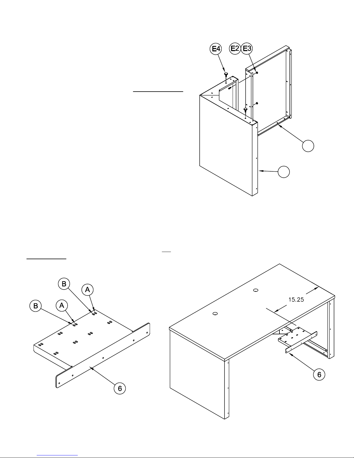
1. Place the Leg (3) on a clean surface. Position the
Modesty Panel (2) next to the Leg with the four slots toward
the floor. Attach the Modesty panel to the Leg with three
Screws (E2) and three KEPS Nuts (E3). DO NOT TIGHTEN
the screws at this time.
2. Install two Glides (E4) into Leg.
3. Turn the assembly to an upright position.
4. Attach the Return Bracket (6) to the previously
assembled furniture. The Return Bracket has mounting
slots for various products. This bracket is used for RIGHT
or LEFT Hand mounting.
2
Slots in the 'A' position are to be used when attaching Tilt
Return to a Credenza only.
Slots in the 'B' position are to be used when attaching Tilt
Return to a Desk, J-Table or P-Table.
5. Align the slots in the Bracket with the holes in the
underside of the work surface that will place the bracket
approximately 15 1/4 inches from outer edge of the work
surface.
6. Attach Bracket with four #10 x 3/4 Screws (E1). DO
NOT TIGHTEN these screws at this time to allow for
alignment.
3
Page 3
(3)
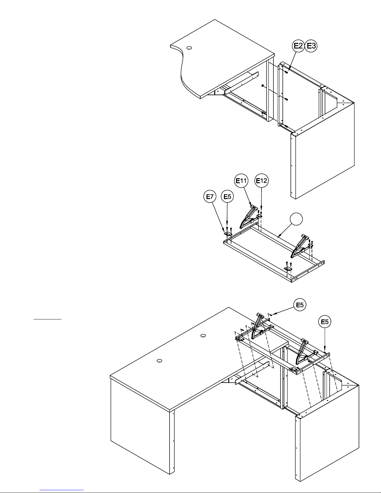
7. Align the holes in the assembled Leg and Modesty Panel
from Step 1 with the end panel on the previously assembled
furniture. Attach using three #10-24 x 3/8 Screws (E2) and
three KEPS Nuts (E3).
8. Attach the two Lift Hinges (E11) to the Frame Assembly using
two Screws (E12) per Hinge. Tighten screws at this time.
9. Attach the two Lower Hinges (E7) to the Frame Assembly
using two Screws (E5) per Hinge. Tighten screws at this time.
10. Install the Frame Assembly (4) between the Leg and the
Mounting Bracket (?). Position the Frame with the Lower Hinges
as shown. Attach the Frame Assembly to the Leg and the
Bracket with three Screws (E5) per side.
4
11. TIGHTEN the screws at this time.
Page 4
(4)
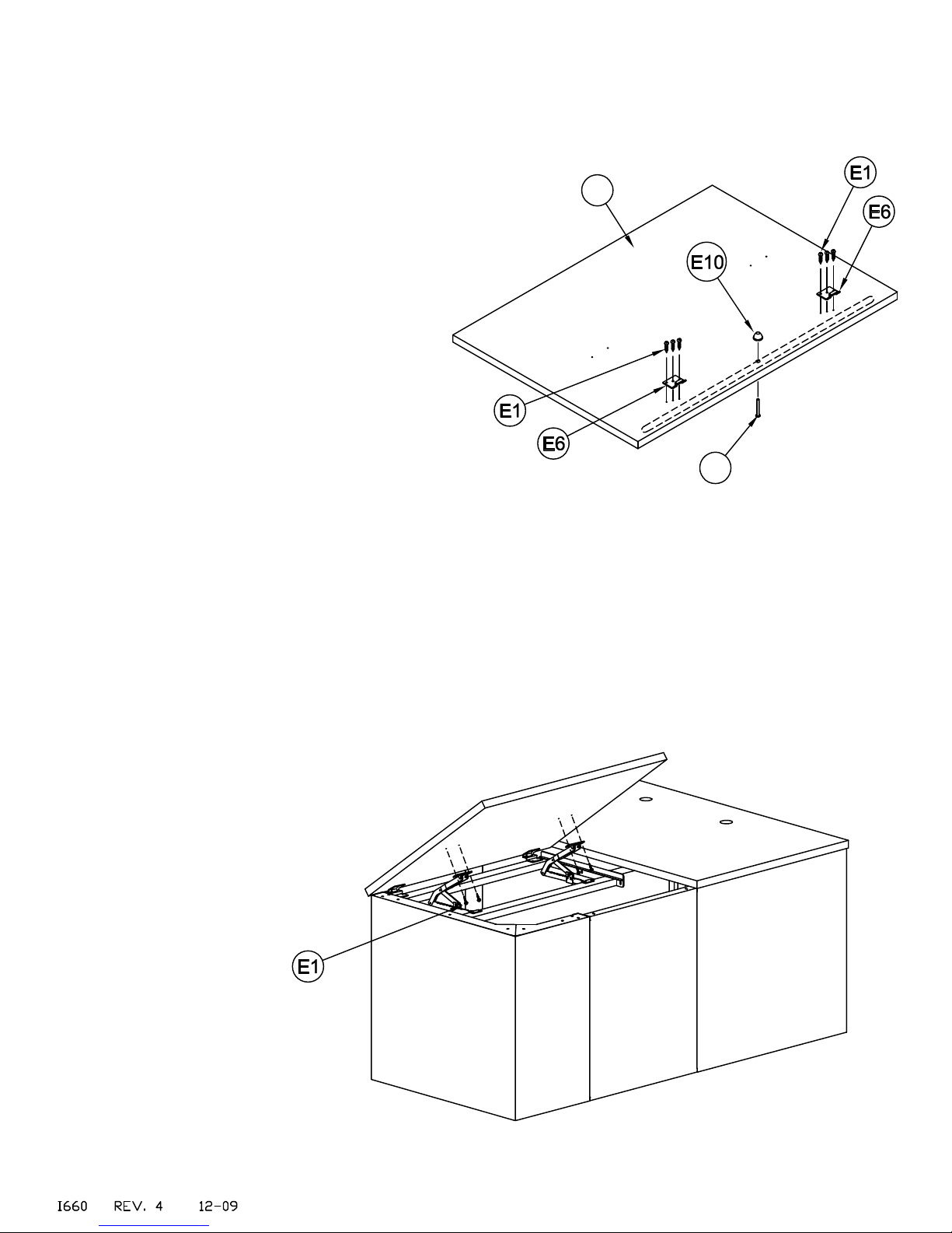
12. Place the Work Surface (1) face down onto a clean surface.
Position the Upper Hinge (E6) with the hinge tab toward the
bottom edge. Secure with six #10 X 3/4 Screws (E1).
13. With the Pencil Stop (5) removed, insert the Rivet (E9) into
the center hole in the groove. Position it with the Rivet head in
the groove and place the Push Nut (E10) on the end of the Rivet
that protrudes beyond the bottom surface.
14. To mount the Work Surface to the base, insert the tabs
of the Upper Hinges into the slots of the Lower Hinges
mounted on the Frame Assembly. Raise the Lift Hinges
until the mounting plate holes are aligned with the pre-drilled
holes in the Work Surface and secure in place with four #10
X 3/4 Screws (E1).
1
E9
15. Apply Rubber Bumpers (E8) near the end of the Frame
Assembly, farthest from the Hinges.
16. Place the Pencil Stop (5) into the
Work Surface groove.
 Loading...