

Page 1
CATALOG No.
7301A
7301B
7301C
NOTE: Please count and inspect all pieces before disposing of any carton or packing materials.
INSTRUCTIONS TO CONVERT RULE TO
ABOVE-BOARD ATTACHMENT
COMPONENTS:
REF.# QTY. DESCRIPTION PART No.
1 CALL~~ Cable Coil CALL~~
2 2 Pulley Housing F314
HARDWARE BAG (PART No. A2297)
*for individual item, order that part number
REF # QTY. DESCRIPTION PART No.
E1 1 R.H. Corner Plate Assembly A2294*
E2 1 L.H. Corner Plate Assembly A2295*
E3 2 Stedge Stop F330*
E4 2 Side Guide B1003*
E5 4 Ball bearing Pulley P14*
E6 2 Washer W42*
When ordering components, specific color and/or size information may be required.
Contact a Mayline Customer Service Representative. 1-800-822-8037
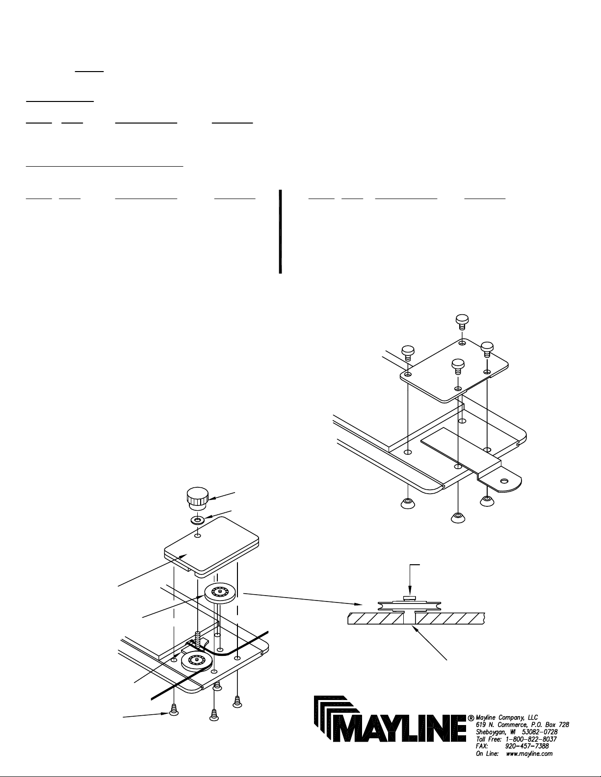
1. Remove present end plates and sliding bars from end of
straightedges. (See Fig. 1)
2. Insert the two Ball bearing Pulleys (E5) into holes located
per Fig. 2 With knurled portion of stud in hole, push down until
shoulder is tight against blade.
REF # QTY. DESCRIPTION PART No.
E7 4 #6 x 1/2" Screw X37*
E8 8 #6 X 1/4" Screw X44S*
E9 2 #6 x 1" Screw X14*
E10 3 Knob K22*
E11 2 Brake Shoe Assembly A2123*
E12 1 Cable Clamp B9*
3. Repeat for other end of Straightedge.
4. Install Cable Assembly. Refer to section "Instructions for
Restringing Mayline Straightedge".
5. Attach straightedge to board. Refer to section " Assembly
Instructions for Mounting Straightedge".
Knob (E10)
Washer (E6)
Pulley
Housing (2)
Ball bearing
Pulley (E5)
NOTE: Brake Shoe (E11)
located under cable
Fig. 2
Fig. 1
Tap
Knurl End
of Pulley
#6 x 1/4"
Screw (E8)
(1)
Page 2
INSTRUCTIONS FOR RESTRINGING
MAYLINE STRAIGHTEDGE
NOTE: Please count and inspect all pieces before disposing of any carton or packing materials.
COMPONENTS:
REF.# QTY. DESCRIPTION PART No.
1 CALL~~ Plastic Cable C1
2 2 Ring Terminal Q6
1. Total cable length required: (3) x (length of straightedge) + 8 feet.
2. Cut total cable length into two equal lengths.
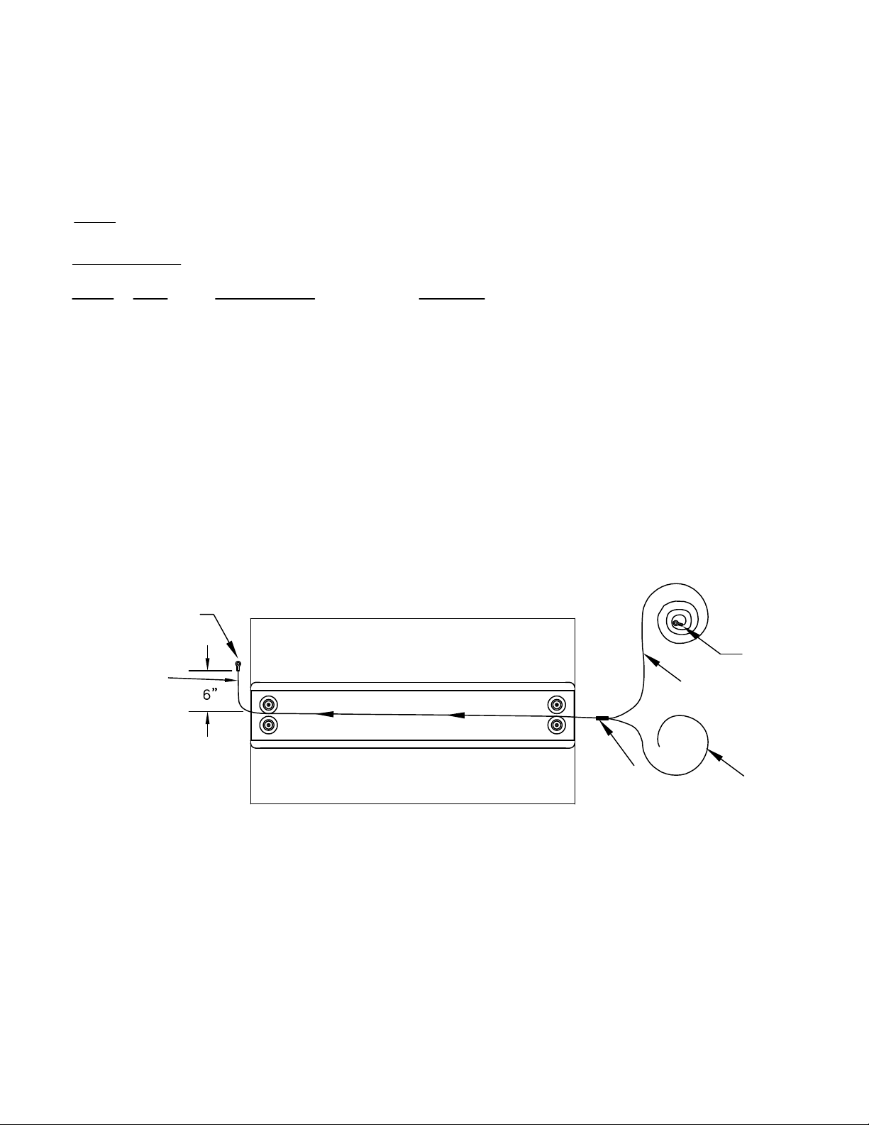
3. Feed one end of Cable 1B through slot in straightedge cap until
approximately 6 inches extends through opposite end. (See Fig. 3)
4. Tape end of Cable 1A to Cable 1B and pull through until 6 inches of
Cable 1A is through opposite end. (See Fig. 3) Remove tape
Ring
Terminal (2)
Cable (1B)
When ordering components, specific color and/or size information may be required.
Contact a Mayline Customer Service Representative. 1-800-822-8037
Ring
Terminal (2)
Cable (1A)
Fig. 3
5. Crimp ring terminals onto the upper ends of cables A & B. (See Fig. 3)
6. Replace pulley housing / brake assembly. (See front page for Fig. 2)
(2)
Tape
Cable (1B)
Page 3

ASSEMBLY INSTRUCTIONS
for MOUNTING STRAIGHTEDGE
Knob (E10)
Pulley Housing
Cover
Side Guide (E4)
Knob (E10)
Fig. #4
Washer (E6)
Cable Clamp (E12)
Washer (E6)
1. Place straightedge in position on Worksurface.
Install Knob (E10) and Washer (E6) on both ends
of straightedge. Do not tighten at this time. (See
Fig. #4)
2. IF STRAIGHTEDGE IS FULL LENGTH OF
WORKSURFACE AND NO SIDE MOTION IS
DESIRED: Insert Side Guides (E4) under pulley
housing cover as shown in Fig. #4. Guides may
be bent with fingers to fit Worksurface.
IF STRAIGHTEDGE IS NOT FULL LENGTH OR
SIDE GUIDES ARE NOT DESIRED: Side Guides
can be eliminated without affecting operation of
unit.
Fig. #5
#6 x 1/2" Screws (E7)
NOTE:
Pre-drilling 3/32" pilot holes is
recommended for these screws.
Left Corner
Plate (E2)
Stedge Stop (E3)
#6 x 1" Screw (E9)
NOTE:
Pre-drilling 3/32" pilot holes is
recommended for these screws.
3. Position Corner Plates (E1) and (E2) so cable
runs parallel with Worksurface edge. (See Fig.
#5). Mark hole locations.
4. Drill 3/32" pilot holes at marked locations.
5. Secure Corner Plates using four #6 x 1/2
Screws (E7). (See Fig. #5)
6. Install cable Clamp (E12) onto Stud of Left
Corner Plate (E2). Be sure cable passes between
Clamp and Corner Plate. Turn Knob (E10) onto
Stud. (See Fig. #5 for correct installation). See
Fig. #7 for Spring position. Tighten Knob (E10)
when spring is centered.
7. Position the Stedge Stop (E3) on the front
edge so the cable is parallel with the Worksurface
sides. Mark holes on the Worksurface edge.
(See Fig. #6) Repeat this step for both sides.
8. Drill 3/32" pilot holes at marked locations.
9. Insert cable through Stedge Stop and attach to
the Worksurface using Screws (E9).
Fig. #6
(3)
Page 4

12. Pull cable on RIGHT side of worksurface to remove
slack from this portion. Tighten Stedge Clamp Screw (E9)
at this time.
13. Pull cable on LEFT side to remove slack. Do not
exceed spring tension (See Fig. #7). Tighten Stedge
Clamp Screw (E9).
14. Excess cable can be trimmed off leaving several
inches for future adjustments.
15. Straightedge may be locked in position by tightening
Knobs installed in Step #1 on both ends of Straightedge or
left loose to allow free movement up or down.
LEFT CORNER
PLATE (E2)
CABLE BRAKE
KNOB
PARALLEL
PARALLEL
SPRING LENGTH
NOT TO EXCEED
SPRING
(CENTER SPRING BETWEEN CORNER PLATES)
ALIGN CABLE PARALLEL
WITH EDGE OF BOARD
RIGHT CORNER
PLATE (E1)
PARALLEL
Fig. #7
(4)
 Loading...