

Page 1

ASSEMBLY INSTRUCTIONS
TRANSACTION 8' CONFERENCE TABLE
NOTE: Please count and inspect all pieces before disposing of any carton or packing materials.
COMPONENTS:
Item # QTY. DESCRIPTION PART #
1 4 LEG A8073**
2 2 PANEL ASSEMBLY TACEP**
3 2 SPREADER B8409**
4 1 TROUGH ASSEMBLY A8104**
5 1 WORKSURFACE CALL**
6 4 OUTSIDE ACCESS PANEL B8410**
When ordering components, specific color and/or size information may be required.
Contact a Mayline Customer Service Representative. 1-800-822-8037
Item # QTY. DESCRIPTION PART #
7 2 CENTER ACCESS PANEL B8311**
8 2 INNER LEG PANEL 14.35" B8299**
9 1 R.H. CONNECTOR PANEL B8312
10 1 L.H. CONNECTOR PANEL B8313
11 1 GROMMET F787BK
12 1 WIRE COVER F784G
** Denotes Color Code
HARDWARE BAG (PART No. A8124)
* for individual item, order that part number
Item # QTY DESCRIPTION PART #
E1 4 TUBE INSERT, 5/16-18 T139*
E2 4 GLIDE Q608*
E3 4 GLIDE Q630*
E4 30 SCREWS #10-32 x 1/2" X204*
E5 28 SCREW #10 x 3/4 X11*
E6 2 SLAM LATCH Q643*
E7 8 SLAM LATCH Q624*
E8 4 FELT PAD E518*
E9 4 STAND OFF B8415*
E10 2 SCREW #6 x 1 X14*
(1)
Page 2
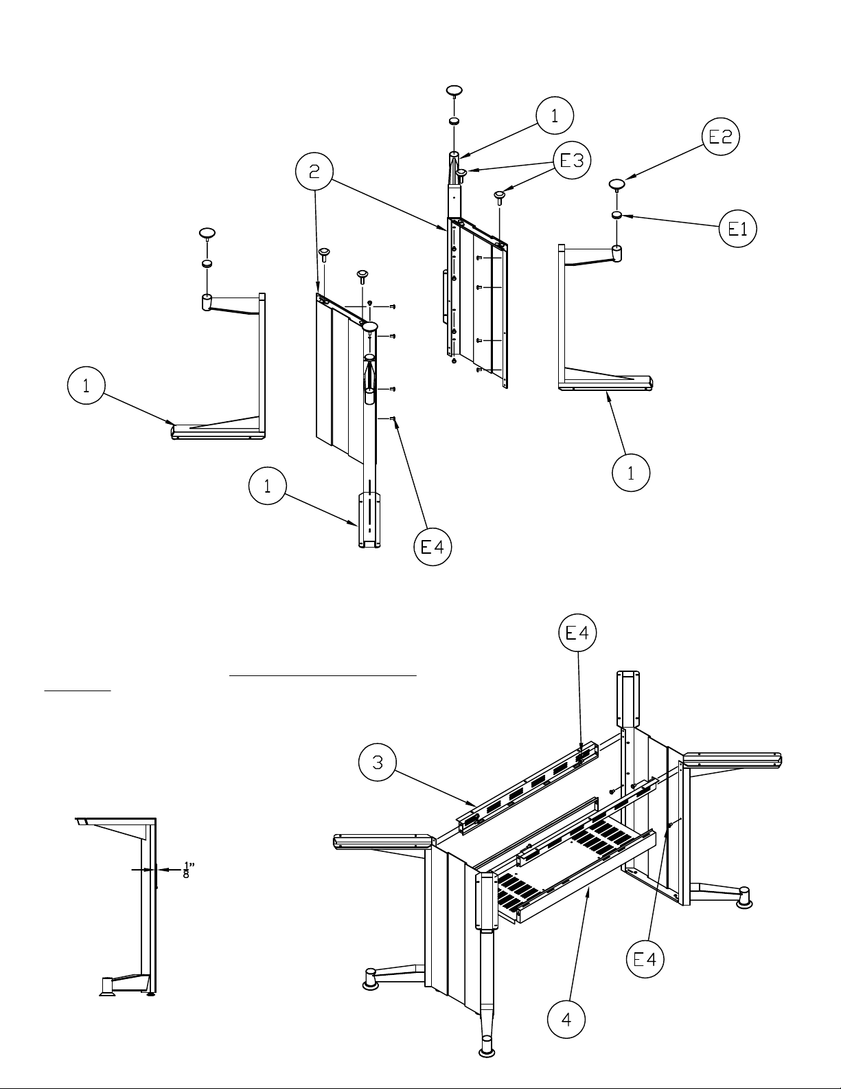
1. Install threaded inserts (E1) into legs
2. Thread glides (E2) into threaded inserts installed in Step 1.
3. Thread glides (E3) into bottom of panel assembly.
4. Attach legs (1) to panel assembly (2) with screws (E4).
5. Partially install screws (E4) into the bottom hole of each leg
assembly so that the screw head is approximately 1/8" from the leg.
6. Using the key hole slots in the ends of the trough assembly (4),
attach trough to leg assemblies. DO NOT TIGHTEN SCREWS AT
THIS TIME.
7. Install spreader (3) between leg assemblies using screws (E4).
8. Tighten screws (E4) for trough (4) and spreaders (3).
(2)
Page 3

9. Position Connector panels (9 & 10) as shown in detail. Attach
Connector Panels (9 & 10) to trough assembly using screws (E4).
10. Install slam latch (E6) into inner leg panel slot (8)
as shown.
11. Insert inner leg panel tables (8) into leg panel
slots. Rotate inner leg panel till slam latch catches
trough assembly (4).
(3)
Page 4

12. Position worksurface on base assembly and
fasten using screws (E5) through legs, spreader and
connector panels.
13. Insert slam latch (E7) into access panels (6 & 7).
14. Install the access panels into the table base by
inserting panel tabs in access panels (6 & 7) into trough
(4) slots. Pivot panels up until latch catches on spreader.
15. Insert grommet (11) into hole in worksurface (5) and
fasten using screws (E10).
16. Attach standoffs (E9) to wire cover (12).
17. Adhere felt pads (E8) to the bottom of standoffs (E9).
(4)
 Loading...