

Page 1
®
Aberdeen Series
Main Desk - Height Adjustable
Model No. ARDHA7236
ARDHA7230
ARDHA6630
ARDHA6030
ASSEMBLY INSTRUCTIONS
CALL 1-800-822-8037 FOR ASSISTANCE
P/N ABDHA REV 1 11/17
www.mayline.com
Page 2
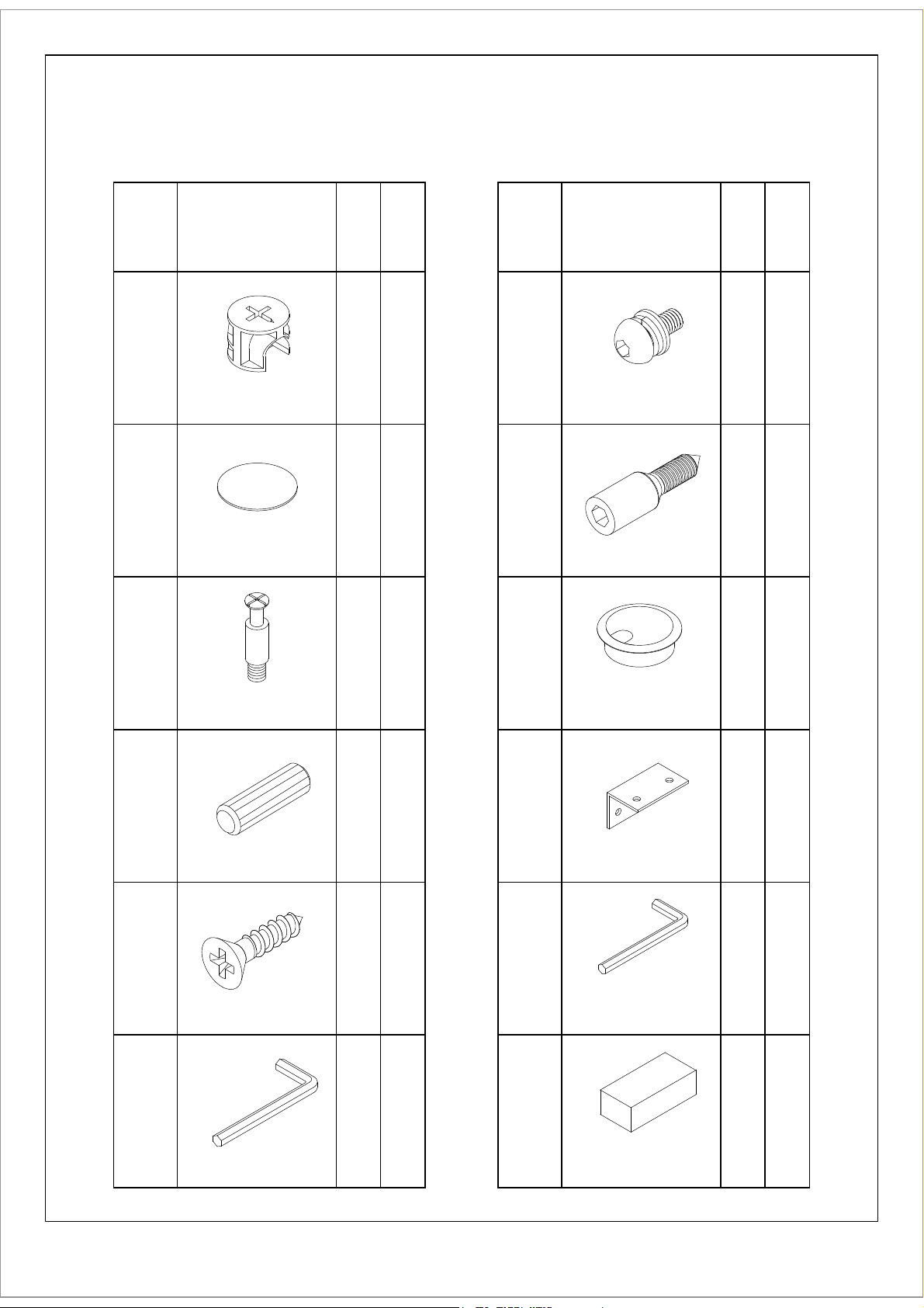
PARTS LIST
ARDHA
Name Part
HB
A
Qty.
8
Spare
Qty
1
REALS001
Cam Lock
HB
B8
1
REALS102
Cam Sticker
HB
C8
1
PartName
HB
Qty.
Spare
Qty
8G
REALS436
M6*15
HB
9H
1
REALS434
M6*33
HB
I
2
REALS003
Cam Post
HB
D8
1
J
REALS004
Wood Dowel
HB
E
17 1
K
REALS005
Wood Screw Ø4*16
HB
F
11
REALS100
Grommet
REALBY047
Corner Bracket
REALS084
Allen Wrench 5mm
E
R
A
W
D
R
A
H
HB
4
HB
1
REALS435
Allen Wrench 4mm
ABDHAHB
1
Page 3
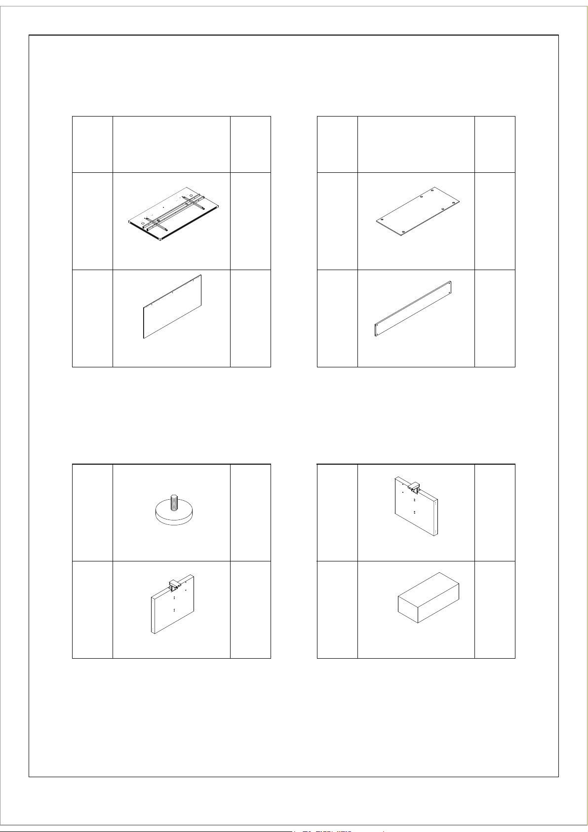
PARTS LIST
ARDHA
L
M
PartName
TOP
Adjustable
Modesty Panel
PARTS LIST
Qty.
Name Part
N
Wire Management
Tray
Fixed Modesty
Panel
Qty.
21
11O
P
REALS437
Levelers
Left Leg
ARDBHA30 / ABDBHA
HB
6
R
1Q
Right Leg
E
R
A
W
D
R
A
H
ABDBHAHB
1
1
2
Page 4
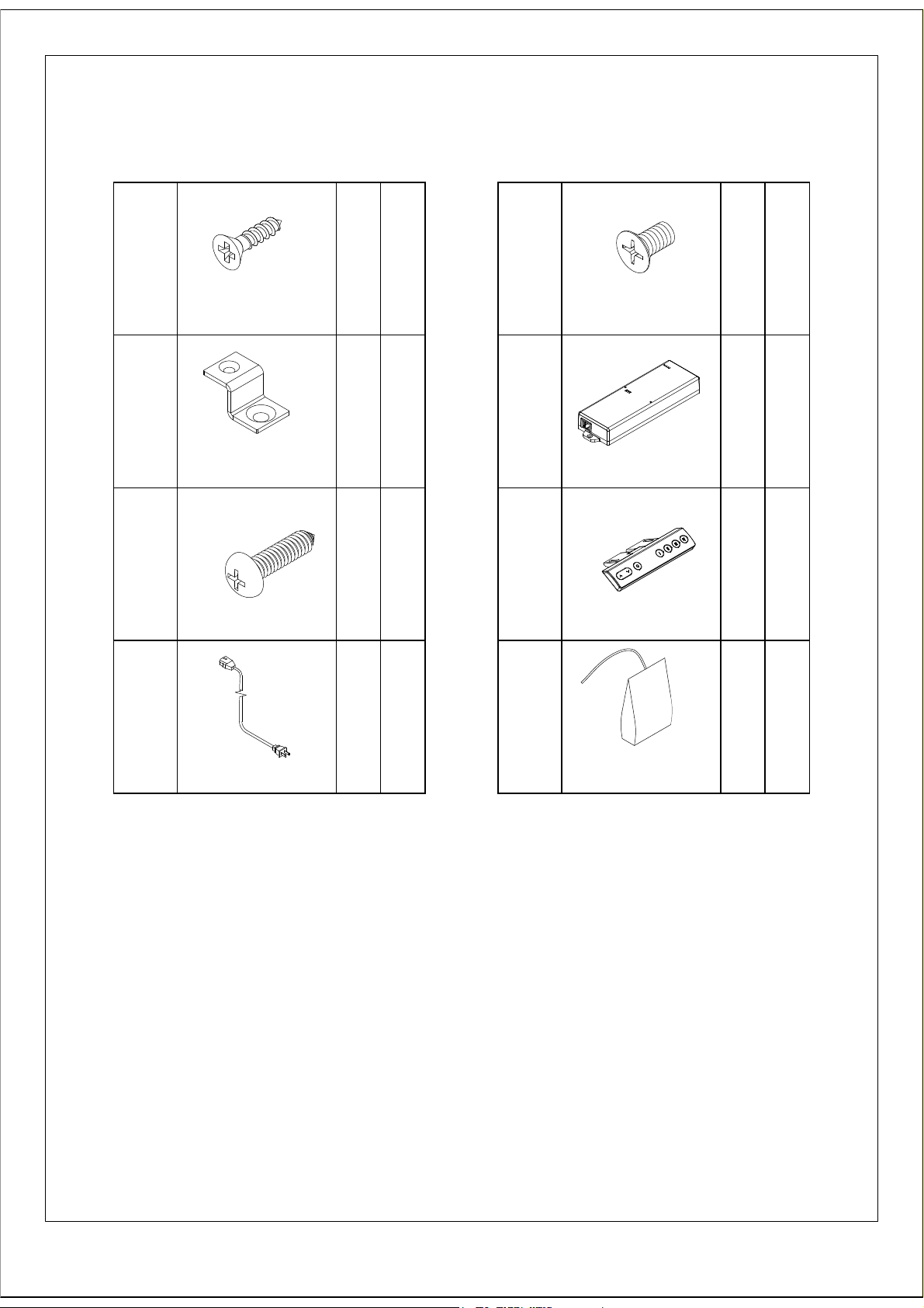
PARTS LIST
Z548/Z549
HB
S3
REALS016
Ø4*16
HB
T
REALS438
Z Bracket
HB
U
REALS442
Ø4x14mm
2
3
1
1
X
Y
REALS440
M6*10
Control box
Controller
HB
3W
1
1
1
V
Power cord
NOTE:
①
.
1 Top
packed in one carton
-
ABDHA7242/ABDHA6642
and
2
Modesty Panel
1
and
2 Wire Management Tray
.
E
R
A
W
D
R
A
H
Z548HB
1
with Hardware
②
③
.
2
Legs
. 1
Control Box and 1
packed in one carton
Power Cord and 1 Controller
3
in one carton
Page 5

IMPORTANT!
Review ALL instructions before beginning assembly. These
instructions are provided to avoid problems that may occur from
improper assembly or installation. Mayline and/or its distributor
are not responsible for failure resulting from improper assembly
or installation of this product. Moreover, all warranties are void
for failure to follow these assembly instructions.
1
install the Levelers (P) into the Legs (R and Q).
O
(R)
and
(Q)
4
Page 6
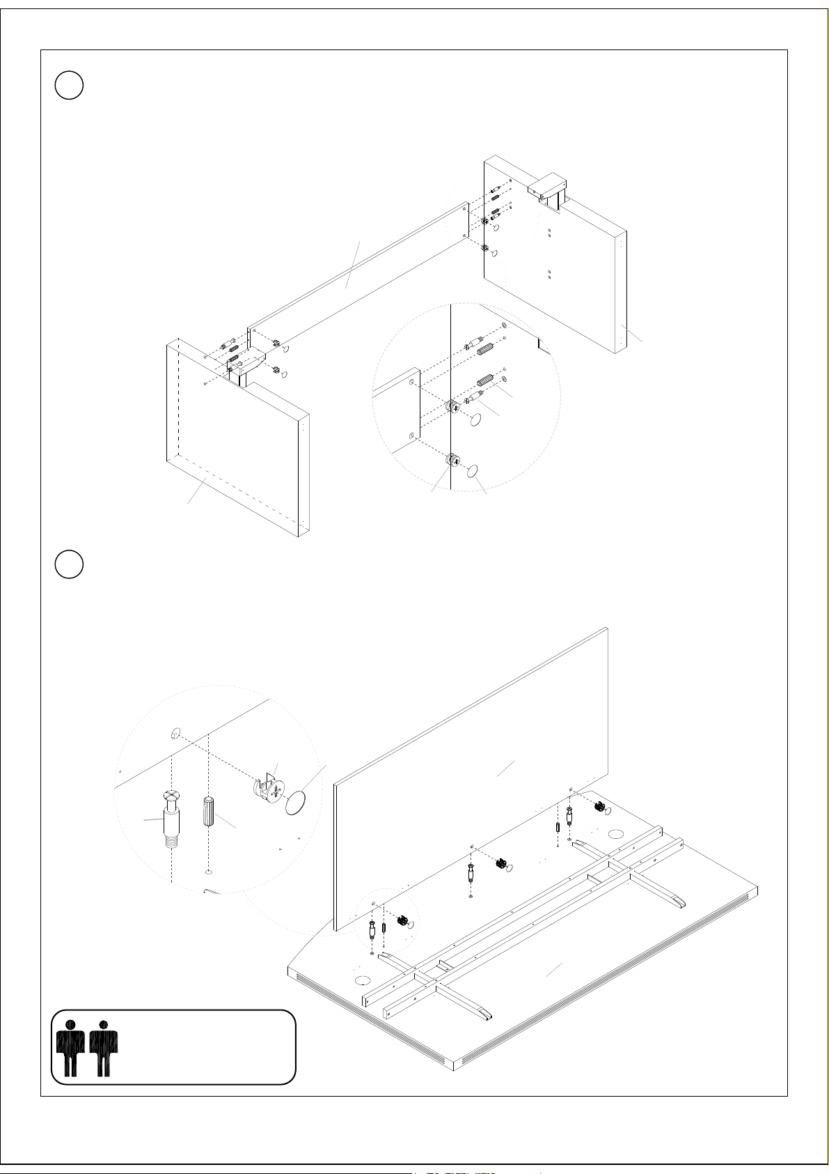
Insert Cams (A) into Fixed Modesty Panel (O). Install Cam Posts (C) into threaded inserts
2
in Top of Legs (R and Q). Attach Fixed Modesty Panel (O) to Legs (R and Q) by turning
Cams (A). Attach Stickers (B) over Cams (A).
NOTE:
Before assembly the top to metal frame,adjust
the SAME HEIGHT of both wood legs
O
R
D
C
Q
A
3
Insert Wood Dowels (D) into the Adjustable Modesty Panel (M), Insert Cams (A)
into Adjustable Modesty Panel (M). Install Cam Posts (C) into the Top (L). Attach
Adjustable Modesty panel (M) to top by turning Cams (A). Attach Stickers (B)
over Cams (A).
A
B
B
M
C
D
TWO PEOPLE REQUIRED
L
5
Page 7

Install the Bracket (T) to the Control Box (X) by Screws (S), Install the Control Box (X)
4
to the Top (L) by Screw (W); Install the Bracket (J) to the Adjustable Modesty Panel (M)
and the Top (L) by Screw (E).
S
X
J
W
T
E
5
Put the Top (L) on the Legs (R and Q).
6
TWO PEOPLE REQUIRED
Page 8

Install the Top (L) to the Legs (R and Q) by Screw (H); Put Memory Controller (Y) on
6
desired location on front edge of top, and fasten with Screws (U).
H
F
U
7
Y
Y
N
G
K
Uninstall the Frame Mounting
Screws, Qty 2, with Wrench (K).
Install Wire Management
Tray (N) to Frame using
Screws (G) and Wrench (K).
Re-install Frame Screws thru
Wire Management Tray.
Page 9

Put the Grommets (I) to the Top (L); Connect power for Control Box (X) using the Power
8
Cord (V) and connect Controller (Y) into the Control Box (V); Plug Power Cord (V) into outlet
and proceed with Controller Initialization. See User Manua;
I
I
X
Y
X
V
8
Page 10

Make sure no obstacles are in the desk's path.
Make sure the desktop is not touching any walls.
Make sure all cords are appropriate length to accommodate
the change in height.
IMPORTANT: You must INITIALIZE the desk prior to first use.
Controller Initialization- Press and hold the Down button on the controller until the desk
reaches its lowest height, slightly raises, and stops. Release the down button, your desk
is now ready for use. (Following the "USER MANUALS" to use your desk)
If the table is not functioning properly it may need to be reset. Unplug the
power cord for 20 seconds. Plug the power cord back in and follow
the RESET procedures;
If the error message persists after the reset procedure, please contact your dealer;
If the height between the legs exceeds 1.5 inches, stop the reset procedure,
please contact your dealer;
TROUBLESHOOTING
9
 Loading...