

Page 1
ASSEMBLY INSTRUCTIONS
TRANSACTION 6' ADDER TABLE
NOTE: Please count and inspect all pieces before disposing of any carton or packing materials.
COMPONENTS:
Item # QTY. DESCRIPTION PART #
1 1 ADDER LEG A8046**
2 2 SPREADER B8376**
3 1 TROUGH ASSEMBLY A8103**
4 1 WORKSURFACE TACT6A**
5 4 OUTSIDE ACCESS PANEL B8378**
When ordering components, specific color and/or size information may be required.
Contact a Mayline Customer Service Representative. 1-800-822-8037
Item # QTY. DESCRIPTION PART #
6 2 CENTER ACCESS PANEL B8311**
7 2 INNER LEG PANEL 11.79" B8411**
8 1 R.H. CONNECTOR PANEL B8312
9 1 L.H. CONNECTOR PANEL B8313
10 1 GROMMET F787BK
11 1 WIRE COVER F784G
** Denotes Color Code
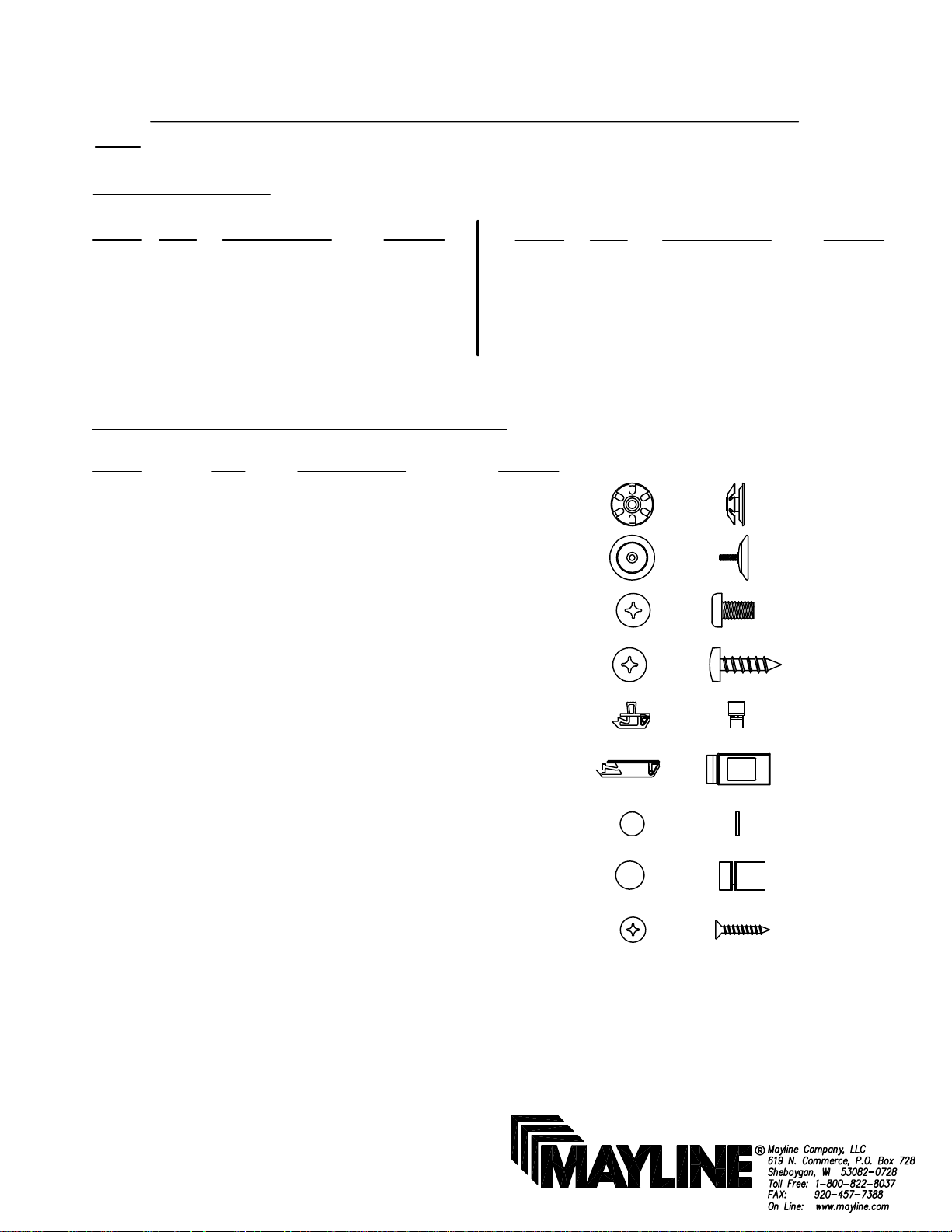
HARDWARE BAG (PART No. A8123) * for individual item, order that part number
Item # QTY DESCRIPTION PART #
E1 2 TUBE INSERT, 5/16-18 T139*
E2 2 GLIDE Q608*
E3 18 SCREWS #10-32 x 1/2" X204*
E4 32 SCREW #10 x 3/4 X11*
E5 2 SLAM LATCH Q643*
E6 12 SLAM LATCH Q624*
E7 4 FELT PAD E517*
E8 4 STAND OFF B8415*
E9 2 SCREW #6 x 1 X14*
(1)
Page 2
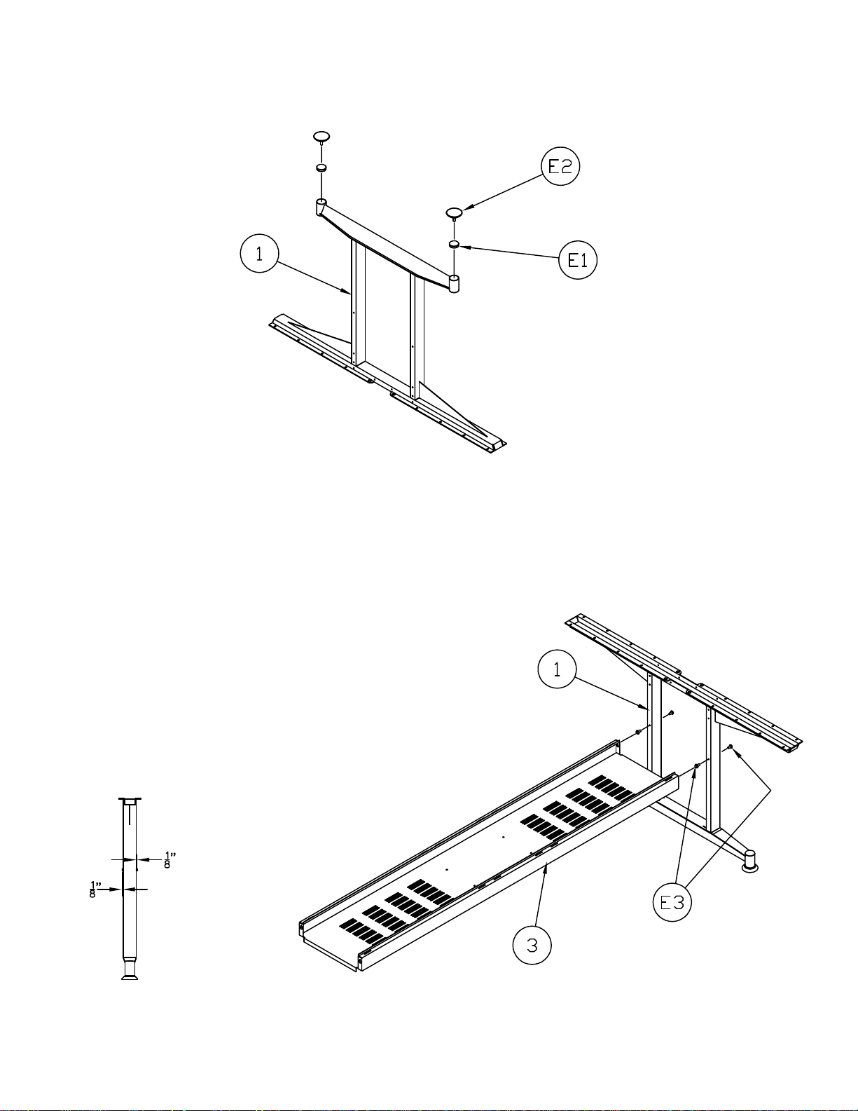
1. Install threaded inserts (E1) into Adder Leg (1).
2. Thread Glides (E2) into threaded inserts installed in Step 1.
3. Partially install Screws (E3) into the bottom hole on both sides of the
Adder Leg (1) so that the screw heads are approximately 1/8" from the leg.
4. Using the key hole slots in the ends of the Trough Assembly (3),
attach Trough Assembly to Adder Leg. Tighten two Screws holding trough.
(2)
Page 3

Starter Base
Hole
remains
OPEN
Partially
installed
screws
5. Assemble Starter Base per instructions included with that product.
6. Move assembled Adder Base into position. Using the key hole slots in
Trough end (3), attach the Trough to the partially installed screws in the
assembled Starter Base.
7. Install two Spreaders (2) to Adder Leg (1) and to assembled Starter
Base using Screws (E3).
8. TIGHTEN ALL SCREWS mounting Spreaders and Trough.
9. Continue the Conference Table assembly by joining another Adder
Base or complete the Conference Table by joining the final section.
10. Install Slam Latch (E5) into Inner Leg Panel slot (7) as shown.
11. Insert Inner Leg Panel (7) into Adder leg foot slots. Rotate Inner
Leg Panel till slam latch catches Trough Assembly (3).
12. Position Connector Panels (8 & 9) as shown in detail. Attach
Connector Panels (8 & 9) to Trough Assembly (3) using screws (E3).
(3)
Page 4

13. Position Starter Worksurface over Starter Base and loosely fasten in place using
hardware and instructions supplied with that product. Position Adder Worksurface (4) on
Adder base and loosely fasten using screws (E4) through legs, spreader and connector
panels.
14. Continue the Conference Table assembly by installing another Adder worksurface
or complete the Conference Table by installing the final worksurface.
Once ALL tops are installed and aligned, tighten all screws.
15. Insert slam latch (E6) into Access Panels (5 & 6).
16. Install the Access Panels into the table base by inserting Panel tabs into Trough
(3) slots. Pivot panels up until latch catches on spreader.
17. Insert Grommet (10) into hole in Worksurface (4) and fasten using Screws (E9).
18. Attach Standoffs (E8) to Wire Cover (11).
19. Adhere Felt Pads (E7) to the bottom of Standoffs (E8).
(4)
 Loading...