

Page 1
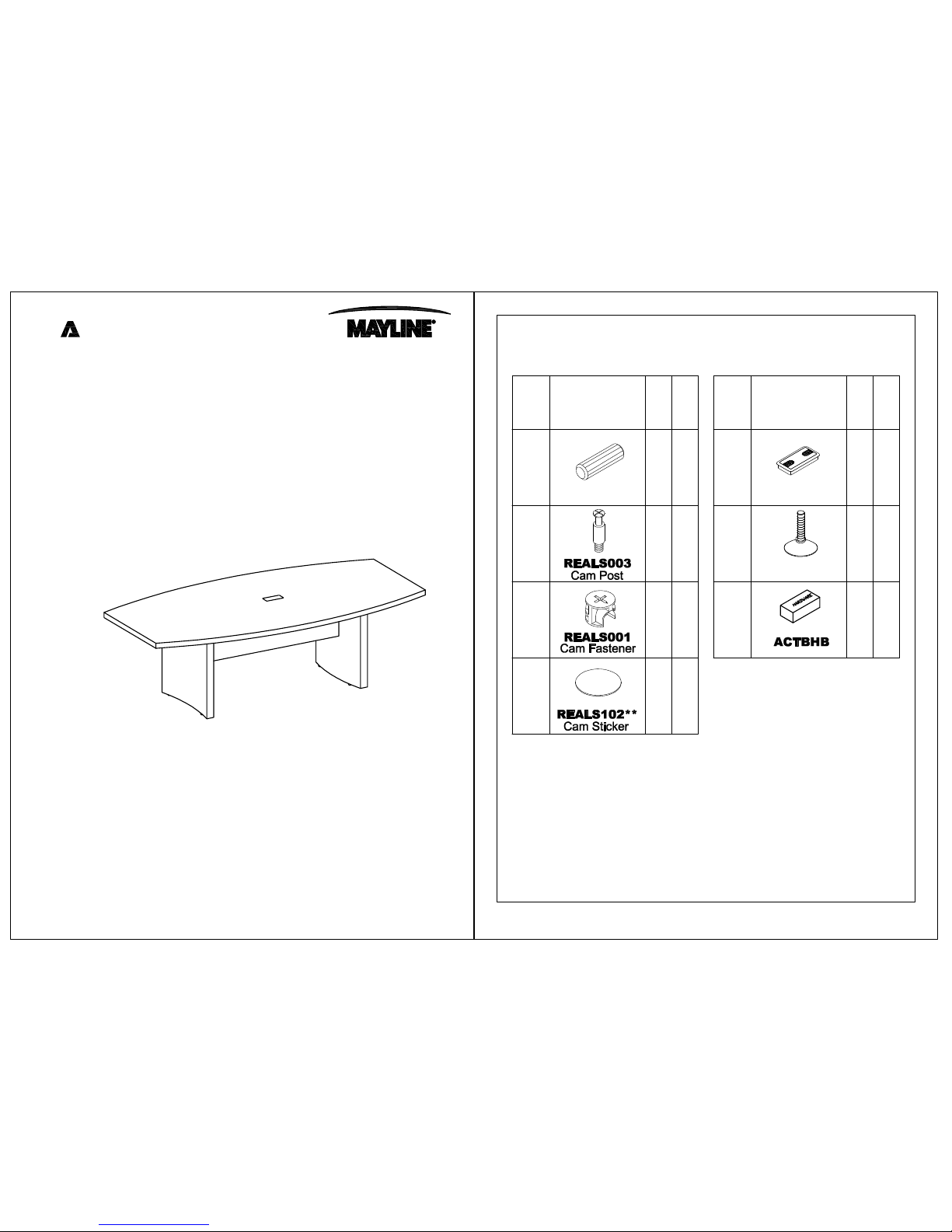
Model No. ACTB6
18
2
F
Name Part
Qty.
Spare
Qty
Spare
Qty
Qty.
PartName
A
18
B
18C
D
1
PARTS LIST
4
8
2
2
HB
HB
HB
HB
HB
Conference Table 72" x 36"
ASSEMBLY INSTRUCTIONS
CALL 1-800-822-8037 FOR ASSISTANCE
P/N ACTB6 REV 06 07/22/14
E
HB
Grommet
REALS099
1
2
REALS004
Wood Dowel
Leveler
REALS067
Items with HB are in hardware box.
**Denotes Color Code
Aberdeen Series
TM
www.mayline.com
o
re l
ffice
Page 2
2
PARTS LIST
2
L
Qty.
PartNameName Part
Qty.
J
K
1
2
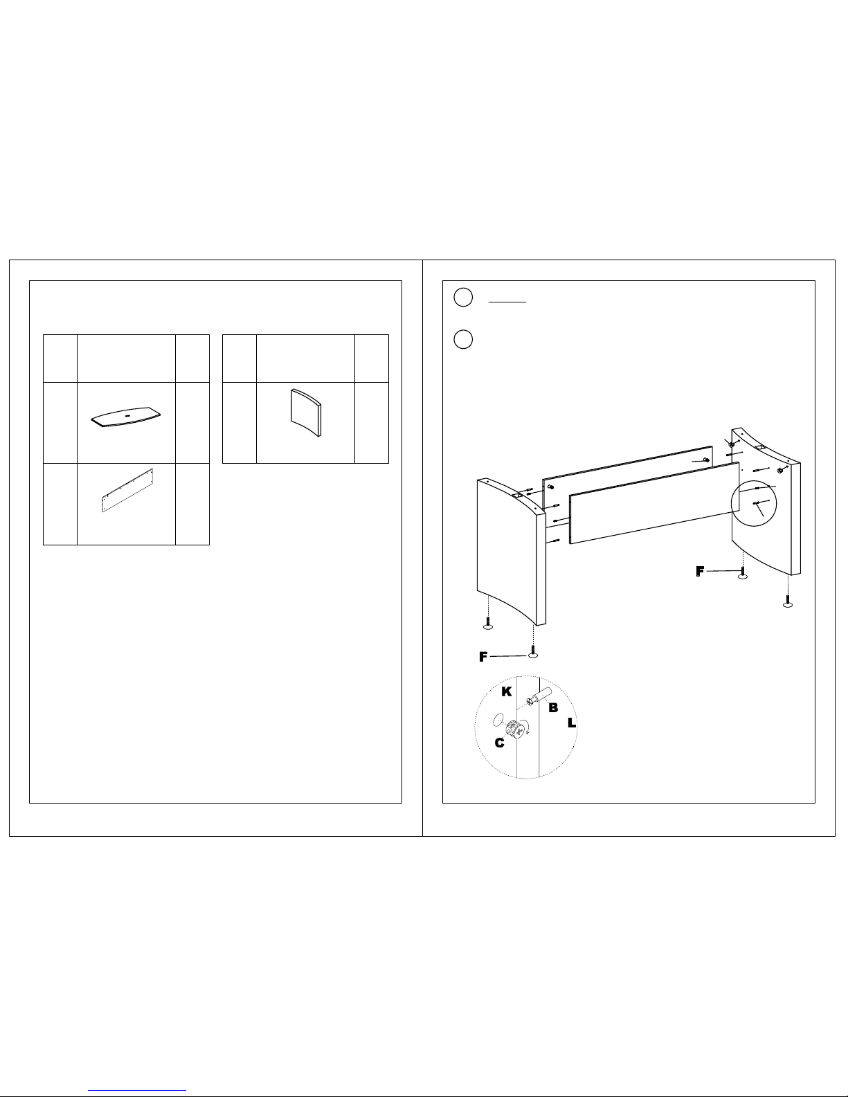
Table Leg
A6LG**
ACTB6K**
Modesty Panel
Top
ABT6**
2 3
NOTE: The arrow on the face of the Cam (C)
should point towards the Cam Post (B) for
proper alignment.
**Denotes Color Code
Insert Wood Dowels (A) and Cams (C) into Modesty Panels (K). Install
Cam Posts (B) into threaded inserts in Table Legs (L). Insert Cams (C)
and install Levelers (F) into Table Legs (L). Secure Modesty Panels (K)
to Table Legs (L) by turning Cams (C).
A
B
C
L
K
K
L
C
IMPORTANT!
Review ALL instructions before beginning assembly .
These instructions are provided to avoid problems that
may occur from improper assembly or installation.
Mayline and/or its distributor are not responsible for
failure resulting from improper assembly or installation of
this product. Moreover, all warranties are void for failure
to follow these assembly instructions.
1
DO NOT assemble table with top to floor. Table must be assembled in
an upright position only.
Page 3
4
3
B
A
J
L
L
K
E
K
J
C
D
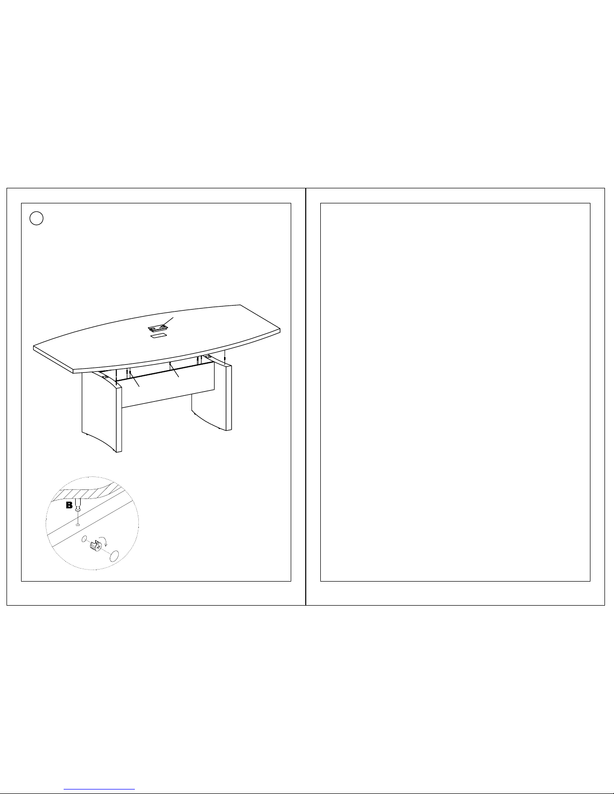
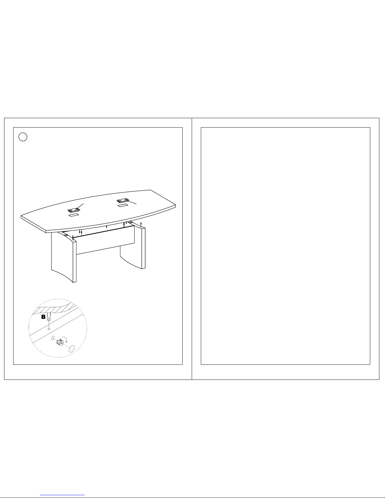
NOTE: The arrow on the face of the Cam (C)
should point towards the Cam Post (B) for
proper alignment.
Insert Wood Dowels (A) into the top of the Table Legs (L) and Modesty
Panels (K). Insert Cams into the Modesty Panels (K). Install Cam
Posts (B) into threaded inserts in the underside of the Top (J). Secure
Top (J) to Modesty Panels (K) by turning Cams (C). Apply Cam
Stickers (D) to exposed Cams (C). Install Cap and Grommet (E).
Page 4

Model No. ACTB8
Conference Table 96" x 48"
18
2
F
Name Part
Qty.
Spare
Qty
Spare
Qty
Qty.
PartName
A
18
B
18C
D
1
PARTS LIST
4
8
2
2
HB
HB
HB
HB
HB
ASSEMBLY INSTRUCTIONS
CALL 1-800-822-8037 FOR ASSISTANCE
P/N ACTB8 REV 07 08/09/10
HB
E
2
REALS004
Wood Dowel
2
Leveler
REAL067
Items with HB are in hardware box.
**Denotes Color Code
Grommet
REALS099
Aberdeen Series
TM
www.mayline.com
o
re l
ffice
Page 5
2
PARTS LIST
1
L
Qty.
PartNameName Part
Qty.
J
K
2
2
2 3
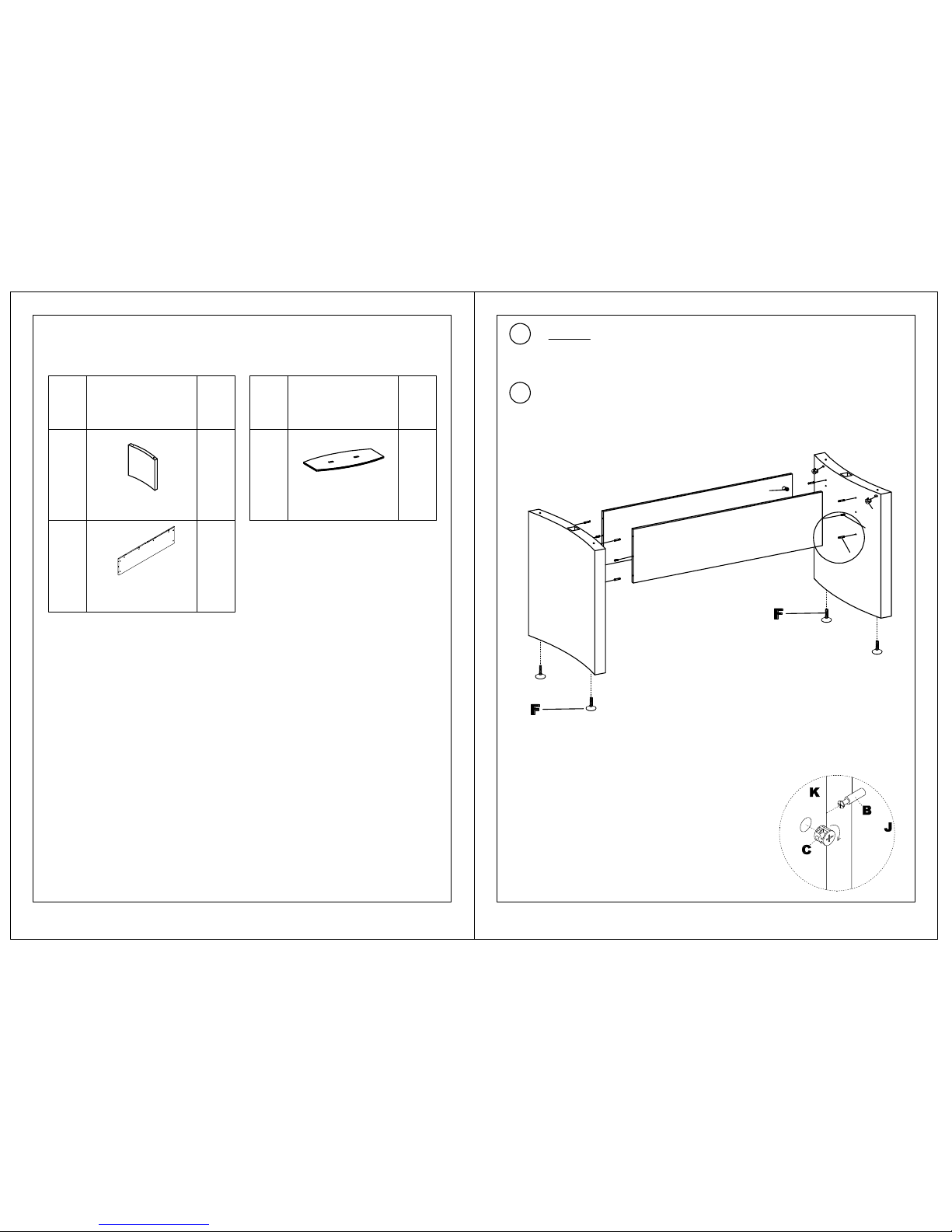
Table Leg
ACLG**
ACM8**
Modesty Panel
Top
ABT8**
NOTE: The arrow on the face of the Cam (C)
should point towards the Cam Post (B) for
proper alignment.
Insert Wood Dowels (A) and Cams (C) into Modesty Panels (K). Install
Leveler (F) and Cams (C) into Legs (J). Install Cam Posts (B) into
threaded inserts in Table Legs (J). Secure Modesty Panels (K) to
Table Legs (J) by turning Cams (C).
A
B
C
J
K
K
J
**Denotes Color Code
C
IMPORTANT!
Review ALL instructions before beginning assembly .
These instructions are provided to avoid problems that
may occur from improper assembly or installation.
Mayline and/or its distributor are not responsible for
failure resulting from improper assembly or installation of
this product. Moreover, all warranties are void for failure
to follow these assembly instructions.
1
DO NOT assemble table with top to floor. Table must be assembled in
an upright position only.
Page 6
4
3
J
J
K
L
E
E
K
L
C
D
NOTE: The arrow on the face of the Cam (C)
should point towards the Cam Post (B) for
proper alignment.
Insert Wood Dowels (A) into the top of the Table Legs (J) and Modesty
Panels (K). Insert Cams into the Modesty Panels (K). Install Cam
Posts (B) into threaded inserts in the underside of the Top (L). Secure
Top (L) to Modesty Panels (K) by turning Cams (C). Apply Cam
Stickers (D) to exposed Cams (C). Install Cap and Grommet (E).
Page 7

1
24
ASSEMBLY INSTRUCTIONS
CALL 1-800-822-8037 FOR ASSISTANCE
PARTS LIST
1
Name Part
Qty.
Spare
Qty
A
B
C 24 2
2
P/N ACTB10 REV 08 07/22/14
Wood Dowel
REALS004
HB
4
2
F
E
Spare
Qty
Qty.
PartName
REALS003
Cam Post
REALS001
Cam Fastener
REALS067
Leveler
Cam Sticker
REALS102**
224
D
HB
HB
HB
HB
HB
ACBT10HB
14
24 2
M6 x 15mm
HB
REALS043
Plate
REALS167
2G
J
H
1
REALS118
Center Plate
Items with HB are in
hardware box
Grommet
REALS099
Conference Table 120" x 48"
Model No. ACTB10
Aberdeen Series
TM
www.mayline.com
o
re l
ffice
Page 8

2
2
3
N
2
2
P
Qty.
PartName
PARTS LIST
Name Part
Qty.
M
1
2
L
ABT10**
Top
ACLG**
Modesty Panel
ACM10**
Table Leg
A
B
C
P
M
ACM10**
Center Panel
P
P
M
NOTE: The arrow on the face of the Cam (C)
should point towards the Cam Post (B) for
proper alignment.
Insert Wood Dowels (A) and Cams (C) into Center Panel (M). Install
Cam Posts (B) into threaded inserts in Modesty Panels (P). Secure
Modesty Panels (P) to Center Panel (M) by turning Cams (C).
A
B
C
Items with HB are in hardware box
**Denotes Color Code
IMPORTANT!
Review ALL instructions before beginning assembly. These
instructions are provided to avoid problems that may occur from
improper assembly or installation. Mayline and/or its distributor
are not responsible for failure resulting from improper assembly
or installation of this product. Moreover, all warranties are void
for failure to follow these assembly instructions
.
1
DO NOT assemble table with top to floor. Table must be assembled in
an upright position only.
Page 9

3
4
4
5
A
B
C
N
P
NOTE: The arrow on the face of the Cam (C)
should point towards the Cam Post (B) for
proper alignment.
Insert Wood Dowels (A) into top edge of each Modesty Panel (P). Insert
Wood Dowels (A) and Cams (C) into the end of each Modesty Panel
(P). Install Cam Posts (B) into threaded inserts in Table Legs (N).
Install Leveler (E) and insert Cams (C) into the Table Legs (N). Secure
Modesty Panels (P) to Table Legs (N) by turning Cams (C).
Install Cam Posts (B) into threaded inserts into the underside of each
Top (L). Attach Plates (H & G) to the underside of Top (L) using
Screws (J).
P
N
N
E
L
P
M
C
B
Page 10

5
6
Place each Top (L) onto the base. Fasten tops (L) together using
Plates (G, H) and Screws (J). Secure Tops (L) to base by turning Cams
(C). Insert Grommet (F) into Tops (L). Apply Cam Stickers (D) to all
exposed Cams (C).
L
L
J
P
Page 11

1
24
ASSEMBLY INSTRUCTIONS
CALL 1-800-822-8037 FOR ASSISTANCE
PARTS LIST
1
Name Part
Qty.
Spare
Qty
A
B
C 24 2
2
Conference Table 144" x 48"
Model No. ACTB12
P/N ACTB12 REV 08 07/22/14
Wood Dowel
REALS004
HB
4
2
F
E
Spare
Qty
Qty.
PartName
REALS003
Cam Post
REALS001
Cam Fastener
REALS067
Leveler
Cam Sticker
REALS102**
224
D
HB
HB
HB
HB
HB
14
24 2
M6 x 15mm
HB
REALS043
Plate
REALS167
2G
J
H
1
REALS118
Center Plate
ACBT10HB
Items with HB are in
hardware box
Grommet
REALS099
Aberdeen Series
TM
www.mayline.com
o
re l
ffice
Page 12

2
2
3
N
2
2
P
Qty.
PartName
PARTS LIST
Name Part
Qty.
M
1
2
L
ABT12**
Top
ACLG**
Modesty Panel
ACM12**
Table Leg
A
B
C
P
M
ACM12**
Center Panel
P
P
M
NOTE: The arrow on the face of the Cam (C)
should point towards the Cam Post (B) for
proper alignment.
Insert Wood Dowels (A) and Cams (C) into Center Panel (M). Install
Cam Posts (B) into threaded inserts in Modesty Panels (P). Secure
Modesty Panels (P) to Center Panel (M) by turning Cams (C).
A
B
C
Items with HB are in the hardware box
**Denotes Color Code
IMPORTANT!
Review ALL instructions before beginning assembly. These
instructions are provided to avoid problems that may occur from
improper assembly or installation. Mayline and/or its distributor
are not responsible for failure resulting from improper assembly
or installation of this product. Moreover, all warranties are void
for failure to follow these assembly instructions.
1
DO NOT assemble table with top to floor. Table must be assembled in
an upright position only.
Page 13

3
4
4
5
A
B
C
N
P
B
L
NOTE: The arrow on the face of the Cam (C)
should point towards the Cam Post (B) for
proper alignment.
Insert Wood Dowels (A) into top edge of each Modesty Panel (P). Insert
Wood Dowels (A) and Cams (C) into the end of each Modesty Panel
(P). Install Cam Posts (B) into threaded inserts in Table Legs (N).
Install Leveler (E) and insert Cams (C) into the Table Legs (N). Secure
Modesty Panels (P) to Table Legs (N) by turning Cams (C).
P
N
N
E
P
M
C
Install Cam Posts (B) into threaded inserts into the underside of each
Top (L). Attach Plates (H & G) to the underside of Top (L) using
Screws (J).
G
Page 14

5
6
Place each Top (L) onto the base. Fasten tops (L) together using
Plates (G, H) and Screws (J). Secure Tops (L) to base by turning Cams
(C). Insert Grommet (F) into Tops (L). Apply Cam Stickers (D) to all
exposed Cams (C).
L
L
J
P
Page 15

1
38
ASSEMBLY INSTRUCTIONS
CALL 1-800-822-8037 FOR ASSISTANCE
PARTS LIST
1
Name Part
Qty.
Spare
Qty
A
B
C 38 2
2
Conference Table 216" x 48"
Model No. ACTB18
P/N ACTB18 REV 04 07/22/14
Wood Dowel
REALS004
HB
6
3
F
E
Spare
Qty
Qty.
PartName
REALS003
Cam Post
REALS001
Cam Fastener
REALS067
Leveler
Cam Sticker
REALS102**
238
D
HB
HB
HB
HB
HB
24
48 2
M6 x 15mm
HB
REALS043
Plate
REALS167
4G
J
H
2
REALS118
Center Plate
ACBT18HB
Items with HB are in
hardware box
Grommet
REALS099
Aberdeen Series
TM
www.mayline.com
o
re l
ffice
Page 16

2 3
P
2
4S
Qty.
PartName
PARTS LIST
Name Part
Qty.
M
1
2
L
ABT18L**
Top
ACLG**
Modesty Panel
ACM18**
Table Leg
ACLG1**
Middle Table Leg
NOTE: The arrow on the face of the Cam (C)
should point towards the Cam Post (B) for
proper alignment.
Items with HB are in the hardware box
**Denotes Color Code
1
N
ABT18N**
Middle Top
2
Insert Wood Dowels (A) and Cams(C) into top edge of each Modesty
Panel (S). Insert Wood Dowels (A) and Cams (C) into the end of each
Modesty Panel (S). Install Cam Posts (B) into threaded inserts in Table
Legs (M&P). Install Leveler (E) and insert Cams (C) into the Table
Legs (M&P). Secure Modesty Panels (S) to Table Legs (M&P) by
turning Cams (C).
S
S
M
P
IMPORTANT!
Review ALL instructions before beginning assembly. These
instructions are provided to avoid problems that may occur from
improper assembly or installation. Mayline and/or its distributor
are not responsible for failure resulting from improper assembly
or installation of this product. Moreover, all warranties are void
for failure to follow these assembly instructions.
1
DO NOT assemble table with top to floor. Table must be assembled in
an upright position only.
Page 17

4
4
5
A
B
C
P
P
NOTE: The arrow on the face of the Cam (C)
should point towards the Cam Post (B) for
proper alignment.
Install Cam Posts (B) into threaded inserts into the underside of each
Top (N). Attach Plates (H & G) to the underside of Top (N) using
Screws (J).
P
S
S
M
S
S
P
3
Insert Wood Dowels (A) and Cams(C) into top edge of each Modesty
Panel (S). Insert Wood Dowels (A) and Cams (C) into the end of each
Modesty Panel (S). Install Cam Posts (B) into threaded inserts in Table
Legs (M&P). Install Leveler (E) and insert Cams (C) into the Table
Legs (M&P). Secure Modesty Panels (S) to Table Legs (M&P) by
turning Cams (C).
B
N
G
H
Page 18

7
6
Install Cam Posts (B) into threaded inserts into the underside of each
Top (L).
L
5
Place each Top (N) onto the base. Secure Top (N) to base by turning
Cams (C). Insert Grommet (F) into Top (N). Apply Cam Stickers (D) to
all exposed Cams (C).
6
N
Page 19

7
L
L
N
P
P
M
S
Place each Top (L) onto the base. Fasten tops (L) together using
Plates (G, H) and Screws (J). Secure Tops (L) to base by turning Cams
(C). Insert Grommet (F) into Tops (L). Apply Cam Stickers (D) to all
exposed Cams (C).
8
 Loading...