

Page 1
corners allow internal adjustment of the rear glides
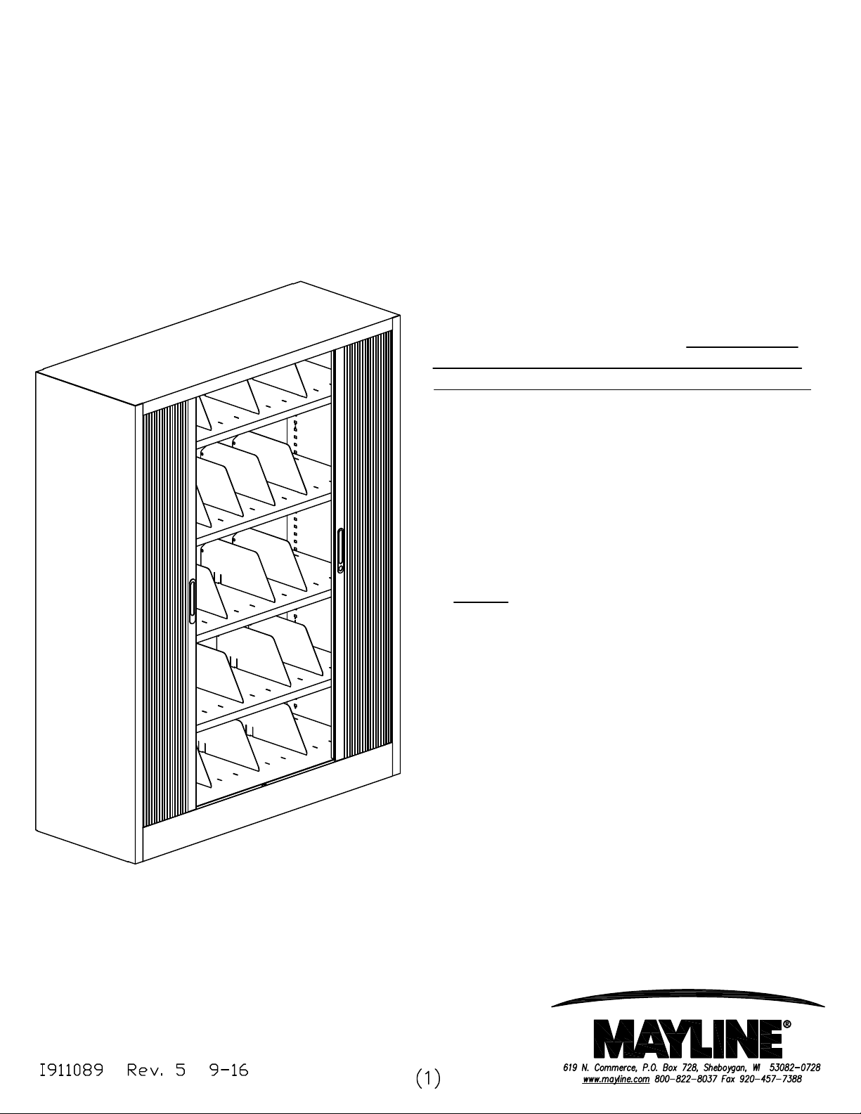
File Harbor Cabinet
Assembly Instructions
Tools Required:
- Blade Screwdriver with long shaft.
1. Remove packaging material. NOTE: Do not
remove packaging material associated with the
doors until unit is upright and in its final location.
This material prevents doors from closing
unexpectedly when the cabinet is placed on its
side for transport.
2. Check for concealed damage. Report any
damage to carrier.
3. Remove the leveling glides that are taped to the
bottom shelf and install.
NOTE: Access holes in the bottom shelf rear
using a blade screwdriver. Access holes are
under the false floor.
4. Remove the keys which are taped to the bottom
cabinet shelf.
5. Install components as required. Call Customer
Service (1-800-822-8037) for assistance if
required.
Page 2
File Harbor Cabinet: Configuration Guide
" for the file folder and
Configuration Guide
Please follow these rules to make sure that the
components for your new File Harbor Cabinet will fit
properly. (If you are ordering a preconfigured cabinet,
these steps won't be necessary).
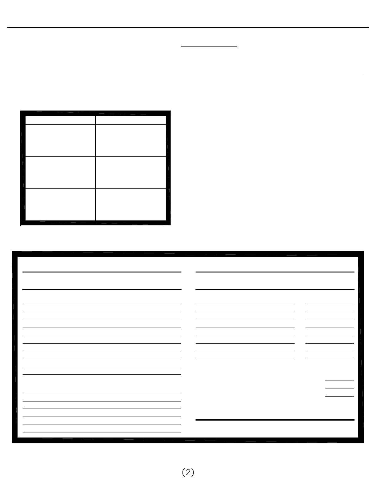
1. Cabinet Interior Height:
Find the interior height of the cabinet you are ordering.
CABINET INTERIORCABINET EXTERIOR
83.00" x 36.00"
83.00" x 42.00"
83.00" x 47.25"
61.50" x 36.00"
61.50" x 42.00"
61.50" x 47.25"
38.00" x 36.00"
38.00" x 42.00"
38.00" x 47.25"
76.77" x 33.25"
76.77" x 39.25"
76.77" x 44.50"
55.25" x 33.25"
55.25" x 39.25"
55.25" x 44.50"
34.80" x 33.25"
34.80" x 39.25"
34.80" x 44.25"
2. Components and Media:
Height Requirement - Find the height required for each of the
components and media you plan to file or store in your File Harbor
Cabinet.
* For example, the MS48 shelf, with color coded end tab files,
requires a height of 11" (1" for the shelf, 9 1/2
1/2"clearance under the shelf above).
See the Components and Media table below:
3. Cabinet Capacity:
Use (or photocopy) the Configuration Worksheet below to add up
the height required for each of the components and media you
need for our cabinet. Then make sure the total component and
media height does not exceed the cabinet's interior height. Use
(or photocopy) the drawing on the next page or sketch the
placement of components.
4. Built-in Bottom Shelf:
All cabinets come with a removable bottom shelf.
5. Additional Top Space:
In some cases cabinet interior height, as shown at left, may be
expanded by using additional space in the very top of the cabinet.
1" located above the door for these components only:
a.) shelf to hang wire dividers
b.) shelf or rail for suspended pockets
Height Required For
Components and Media
MS48/42/36 Shelf w/color-coded end-tab files 11"
MRS48/42/36 Ref. Shelf w/color-coded end-tab files 11"
MS48/42/36 Shelf w/MSPsuspended pockets 11"
MR48/42/36 Rail w/MSP suspended pockets 11"
MS48/42/36 Shelf with 3-ring binders 13"
MRP481/421/361 Roll-out Frame with Pendaflex 10"
MO48/42/36 Organizing System 14"
MOS48/42/36 Master Shelf with dividers for binders 14"
Components Only
MS48/42/36 Shelf; MRS48 / 36 Reference Shelf 1"
MRF481/421/361 Roll-out Frame or Drawer (single) 4"
MFD48/42/36 Adjustable filing Dividers 6"
MWD Wire Dividers 9"
Configuration Worksheet
Components model no.
and / or description Height Required
Total Configuration Height Required:
Cabinet Model No.:
Interior Height:
Questions?
Call Customer Service at 1-800-822-8037
* For standard Interlock to function correctly, 5" spacing is required between Roll-out Drawers, with
10" spacing between Roll-out Frames. Call Customer Service for custom Interlock spacing.
Page 3

File Harbor Cabinet: Replacement Parts
Name Part
A
Name Part
C
912102R
DOOR STOP KIT
For 38" High Units
910979R
1/4-20 X 1 GLIDES
Qty.
Name
1
D
Qty.
1
Name Part
For 62" & 83"
High Units
B
910080R
1/4-20 X 1 1/2 GLIDES
Part
Qty.
1
Qty.
1
COLOR
83" CABINET62" CABINET38" CABINET
36" WIDE CABINET
DOOR KIT w/SLAM RAIL
Track Kit 36" Wide Cabinet..........920077R
Track Kit 42" Wide Cabinet..........920076R
Track Kit 48" Wide Cabinet..........920075R
42" & 48" WIDE CAB.
DOOR KIT w/SLAM RAIL
REPLACEMENT
SLAM RAIL
REPLACEMENT
12 SLAT KIT (1 DOOR)
REPLACEMENT
24 SLAT KIT (2 DOORS)
Page 4

File Harbor Cabinet: Shelves and Dividers
76.77"
55.25"
6. Roll-out Configuration and Interlock.
*All roll-out components come standard with Interlock
*Roll-out components must be used adjacent to, or continuous
with each other in the cabinet for the Interlock to function.
Roll-out components must not be positioned higher than 50" from
the inside bottom of the cabinet to maintain safe stability.
36.00"
42.00"
47.25"
*Standard configurations for roll-outs are as follows:
Roll-out frames:
10" apart (limited to 5 roll-out frames in
83" / 62" H cabinets.
Roll-out drawers:
5" apart (limited to 10 roll-out drawers in
83" / 62" cabinets.
*Single roll-out: When there is only one roll-out in a cabinet, it
can be located anywhere in the cabinet as long as it is no higher
than 50" above the inside bottom of cabinet.
*Custom Interlock spacing is available for customers who
want to file/store media which differs from standard 5" or 10"
spacing. Call Customer Service for more information.
7. Configuration: Final Step. It is normal to have a little space
left over when configuring a cabinet. If this is the case, you may
install components a little farther apart then required (except
multiple roll-outs, which have fixed positions), or sometimes add
a shelf and use the extra space for storage.
33.25"
39.25"
44.50"
83.00"
4.5"
83"
Cabinet
8. Installation: Each File Harbor component comes with
installation instructions. All components are installed in slots
located in the inside end panels (spaced exactly 1" vertically
.
apart)
36.00"
42.00"
47.25"
33.25"
39.25"
44.50"
38.00"
1.5"
34.80"
38"
Cabinet
36.00"
42.00"
47.25"
33.25"
39.25"
44.50"
61.50"
4.5"
62"
Cabinet
Page 5
File Harbor Cabinet: Shelves and Dividers
MS48: 42" Shelf for 48" wide Cabinet
MS42: 36 3/4" Shelf for 42" wide Cabinet
MS36: 30 3/4" Shelf for 36" wide Cabinet
MFD48: Adjustable Filing Dividers with backstop for 48" wide Cabinet
MFD42: Adjustable Filing Dividers with backstop for 42" wide Cabinet
MFD36: Adjustable Filing Dividers with backstop for 36" wide Cabinet
911196R
NO Tools Required:
To Install Shelf.
1. Remove packaging material. NOTE: Check for concealed damage. Report damage to carrier.
2. Remove the 4 shelf clips from the plastic bag taped to the underside of the Reference Shelf.
Remove the optional Backstop from the underside of the shelf when ordered.
REPLACEMENT
SHELF HOOK
(BAG of 4 PIECES
3. See the Configuration Guide (page 2) that gets shipped with the cabinet along with the
initial set up instructions for the recommended spacing between shelves. For example, if you are
storing color-coded end-tab files, 11 slots will be needed for the Shelf and its file folders (or 10 slots
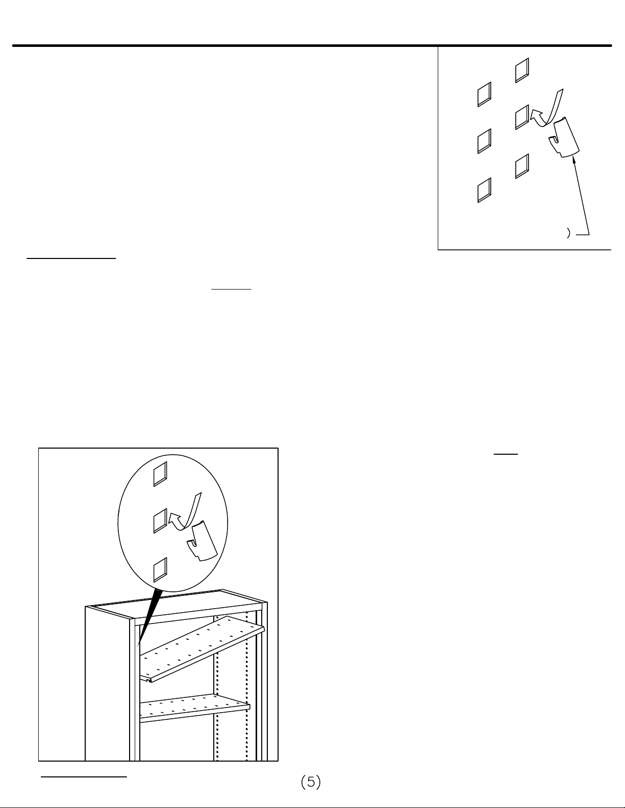
between shelves). Place the shelf clips in the proper holes in the inside end panels.
(See Fig. A)
Fig. A
4. Make sure the cabinet doors are fully open.
While facing the cabinet, hold the Shelf right side up
(the front and back of the Shelf are interchangeable).
Tip one end of the Shelf higher than the other end to
clear the doors. See Fig. A
5. Move the Shelf inside the cabinet above the shelf
clips until the back of the Shelf gently touches the
back of the cabinet.
6. Level the Shelf and lower it onto the Shelf clips. If
it is loose, check that the four shelf clips are level,
and that the Shelf end flanges are properly engaged
with the shelf clips.
Installing the Shelf
Page 6
File Harbor Cabinet: Shelves and Dividers
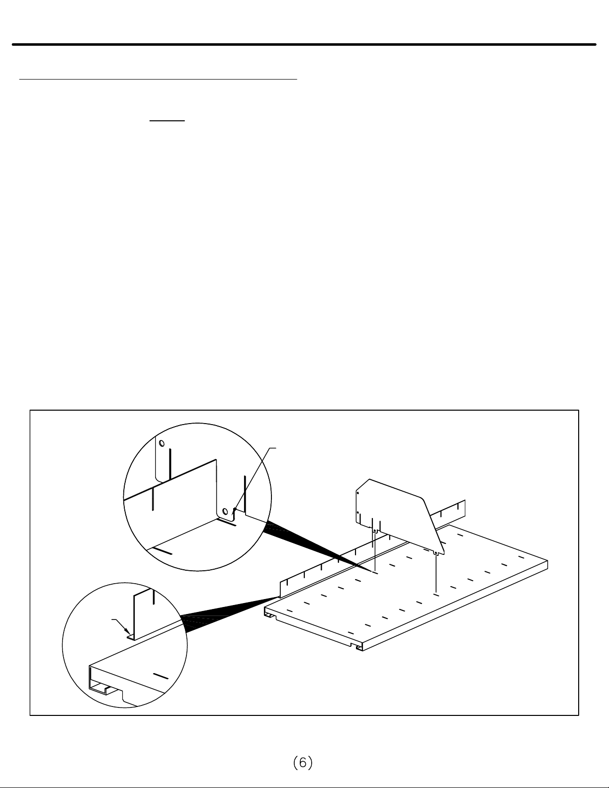
To install Adjustable Filing Dividers and Backstop:
1. Remove packaging material from the Dividers. Remove the Backstop which is taped to the
underside of the shelf. NOTE: Check for concealed damage. Report damage to carrier.
2. There are 3 slots in each Divider. These slots govern the placement of the Backstop depending on
the size of the file folders to be used. For example; using the Divider's middle slot will make typical
letter-sized color-coded end tab file folders line up about 1/8" behind the front of the shelf.
(See Fig. B)
3. Place the Backstop along the length of the shelf an inch or two from the rear of the cabinet with the
slots facing up. The small section, or Backstop foot, should face the rear of the cabinet. Hold the
Backstop in place with one hand. (See Fig. B)
4. Take one of the Adjustable Filing Dividers in your other hand, with the slots underneath and toward
the rear. Move the divider so that one of its slots engages the Backstop as you insert the Divider's
feet into the shelf slots. (See Fig. B)
5. Install the other 3 Adjustable Filing Dividers (2 dividers for 36" wide cabinets) the same way.
Although the distance between the Dividers will depend on user preference, in most cases they will be
placed in every third shelf slot.
Fig. B
DIVIDER
FEET
BACK
STOP
FOOT
Installing the Adjustable Filing Dividers and Backstop
Page 7

File Harbor Cabinet: Reference Top
38" High File Harbor Cabinet
Upper Reference Surface:
To install the Upper Reference Surface:
1. Remove packaging material. NOTE: Check for concealed damage. Report any
damage to carrier.
2. To install the Upper Reference Surface successfully, clean the top of the cabinet to
remove all dust and grim.
3. Remove one protective liner from each piece of double sided tape and apply one
piece to each corner of the File Harbor Unit.
38.00"
4. Remove the remaining protective liner from
all pieces of Tape. Position Reference Surface
with equal amount of overhang all around.
5. Press firmly into position.
Double Sided Tape
36.00"
42.00"
47.25"
Page 8

File Harbor Cabinet: Reference Shelf
MRS48: 42" Reference Shelf for 48" wide Cabinet
MRS42: 36 3/4" Reference Shelf for 42" wide Cabinet
MRS36: 30 3/4" Reference Shelf for 36" wide Cabinet
Tools required: Blade Screwdriver
911196R
REPLACEMENT
SHELF HOOK
To install the Reference Shelf:
1. Remove packaging material. NOTE: Check for concealed damage. Report any damage to
carrier.
2. Remove the 4 shelf clips from the plastic bag taped to the underside of the Reference
Shelf. Remove the optional Backstop from the underside of the shelf when ordered.
(BAG of 4 PIECES)
3. To install the Reference Shelf successfully, you will need about 15" clear space above
it in the cabinet (no components installed in the space).
Fig. C
4. See the attached Configuration Guide
for the recommended spacing between
shelves. For example, if you are storing
color-coded end-tab files, 12 slots will be
needed for the Reference Shelf and its
file folders (or 11 slots between
shelves). Place the Shelf clips (small
tips with flat ends are inserted upwards)
in the proper slots in the inside end
panels. (Fig. C)
5. Make sure the cabinet doors are fully
open. While facing the cabinet, hold the
Reference Shelf right side up. Tip one
end of the shelf higher than the other
end to clear the doors. (Fig. C)
Installing the Shelf
6. Move the Reference Shelf inside the
cabinet, keeping it at least a few inches
above the shelf clips until the back of the
shelf gently touches the cabinet back.
Page 9

File Harbor Cabinet: Reference Shelf
7. Level the Reference Shelf, be sure to keep it above the shelf clips. Kneel down with your hands
under the shelf so that you can see the bottom of the shelf clearly. Tip the front of the shelf up at
about a 45 degree angle.
8. Move the Reference shelf carefully so that the rear side flange slots begin to slide over the rear
shelf clips. (Fig. D)
9. Ease the front of the Reference Shelf down and push the shelf back till the rear shelf clips are
resting against the ends of the rear side flange slots . As the shelf becomes level, the front
notches in the shelf side flange should engage the front shelf clips.
10. Make sure that the Reference Shelf is firmly seated in place. If it is loose, check that the four
shelf clips are level and that the Shelf end flanges are properly engaged with the shelf clips.
Fig. D
Reference shelf installation: engagement with rear shelf clips
Page 10

File Harbor Cabinets: Roll-out Accessories
MRD482: Roll-Out Drawer with Dividers for 48" Cabinet
MRD422: Roll-Out Drawer with Dividers for 42" Cabinet
MRD362: Roll-Out Drawer with Dividers for 36" Cabinet
MRF482: Roll-Out Frame for 48" Cabinet
MRF422: Roll-Out Frame for 42" Cabinet
MRF362: Roll-Out Frame for 36" Cabinet
MRP482: Roll-Out Frame for Pendaflex for 48" Cabinet
MRP422: Roll-Out Frame for Pendaflex for 42" Cabinet
MRP362: Roll-Out Frame for Pendaflex for 36" Cabinet
Tools required: Rubber hammer (or Steel Hammer with Wooden Block)
Blade Screwdriver
NOTE: Assembly of the Roll-Out Accessories is performed inside the File
Harbor Cabinet. Illustrations are shown without the cabinet for clarity.
1. Remove packaging material. NOTE: Check for concealed damage. Report any damage to
carrier. Note that slides are located one at each end of the box.
2. For each roll-out ordered, install an Interlock Locking pin to lock two of the slides together.
NO Interlock Locking Pin is required for a cabinet with only one roll-out accessory- proceed with
installation and ignore all Interlock instructions.
3. The locking pin will be installed so that it inserts into the adjoining roll-out. Only the left-hand
slide has the front black plastic connector bar for the Locking Pin.
4. NOTE: If two or more roll-outs will be installed in the cabinet, the Interlock "MUST" be installed
to ensure stability. Multiple roll-outs must be installed adjacent to each other for the Interlock to
function.
5. Decide where the roll-outs will be located in the cabinet. (The Configuration Guide shows the
recommended spacing for different components and media). Roll-out frames, for standard hanging
file folders, are designed to be installed on 10" vertical increments. Roll-out drawers, where
stored material is no more than 4 1/2" high, are designed to be installed on 5" vertical increments.
"DO NOT INSTALL" roll-out components more than 50" above the bottom cabinet shelf.
Page 11

File Harbor Cabinets: Roll-out Accessories
6. To install the Slide Mounting Brackets (a left and right for each roll-out in the cabinet):
a. Once you have decided where the roll-outs will be installed, find the left-hand slide/mounting
bracket. With the rear two tabs facing the rear of the cabinet and the front two tabs facing
downward, (by sliding horizontally towards the rear of the cabinet) insert the two bracket tabs
into the correct component installation slots at the rear of the inside end panel.
b. Raise the front of the slide/mounting bracket slightly and align with the correct slots at the
front of the inside end panel. With a downward motion, engage the two forward tabs. You
may need to tap the front of the bracket with a hammer to fully engage the bracket.
c. Now install the right-hand slide/mounting bracket so that it is level with the left-hand bracket
just installed. Use the index marks (on the top and bottom of every fourth installation slot)
to help you count and find the correct slot.
SLIDES HOOK
INTO BRACKET
PLASTIC CONNECTOR
BRACKETS HOOK
INTO CABINET
BAR - L.H. ONLY
7. To install the Progressive Slide (a left and right for each roll-out in the cabinet). Only the
left-hand slide has the plastic connector bar at the front.
a. With the rear tab facing the rear of the cabinet and the front tab facing downward, insert
the slide tab into the rear opening of the mounting bracket.
b. Raise the front of the slide slightly. Using a downward motion, engage the forward tab
into the front mounting bracket. You may need to tap the front of the slide with a hammer
to fully engage the bracket.
c. Now install the right-hand slide.
Page 12

File Harbor Cabinets: Roll-out Accessories
8. To install the roll-out frame onto the slides:
a. Pull both slides out as far as they will go.
b. NOTE: The slide loops fit into the frame side knockouts. Bring the frame down from above the
extended slides.
c. Push the frame side knockout tabs through the loops on one slide, then spread the slides
apart to engage the tabs on the other side of the frame. If you cannot insert the tabs all the way
into the slots, use a rubber hammer (or steel hammer and wood block) to force the frame down
onto the slides.
When the frame is fully seated in the slides, use a screwdriver and hammer to push open
the small tab on each frame side slightly so that it extends just past the frame side. This will
prevent the frame from coming off the slide.
PLASTIC CONNECTOR
BAR - L.H. ONLY
PUSH OPEN THIS
SMALL TAB
PUSH OPEN THIS
SMALL TAB
ROLL-OUT FRAME
Page 13

File Harbor Cabinets: Roll-out Accessories
9. NOTE: There are both long (10") and short (3") Interlock Locking Pins depending on the roll-out
component. Short pins are used for 5" spacing as required for the MRD48 / MRD42 / MRD36.
The long pins are used for 12" spacing as required for the MRF48 / MRF42 / MRF36 and the
MRP48 / MRP42 / MRP36.
10. To install the Interlock Locking Pin (if two or more roll-outs are to be installed):
a. With the Roll-Out Frames retracted into the cabinet, take the locking pin and press it into the
plastic bracket near the front of the left-hand slide till it snaps in place. Press the other
end of the pin into the slide bracket on the second roll-out.
b. With all roll-outs closed, open and close each roll-out once or twice to make sure the suspension
is operating correctly.
c. With one rollout extended to the open position, try to open another roll-out. The Interlock
should prevent it from opening.
PLASTIC CONNECTOR
BAR - L.H. ONLY
INTERLOCK LOCKING PIN
Page 14

File Harbor Cabinets: Organizing Systems
NOTE: A wide variety of supports and shelving for the File Harbor Cabinets may be configured by
ordering and combining individual components.
No tools required.
To install Master Shelf with organizing supports and shelving:
1. Remove packaging material from all parts. NOTE: Check for concealed damage. Report any
damage to carrier.
2. Install the Master Shelf:
a. Remove the 4 shelf clips from the plastic bag taped to the underside of the Master Shelf.
b. Note that all support and shelving combinations will require 14 slots of vertical space in the
cabinet for the Master Shelf and shelf supports.
c. Put the shelf clips (small tips with flat ends inserted upwards) - in the proper slots in the inside
end panels. (See Fig. E)
d. Make sure the cabinet doors are fully open.
Face the cabinet holding the Master Shelf with
its slotted back to the rear.
e. With one end of the Master Shelf tipped up,
move it into the cabinet above the shelf clips,
until the back of the shelf gently touches the
cabinet back.
f. Level the Master Shelf, then ease it down onto
the shelf clips. Make sure that it is firmly seated
in place. If it is loose, check that the four shelf
clips are level and that the shelf end flanges are
properly engaged with the shelf clips.
Fig. E
Installing the Master shelf
Page 15

File Harbor Cabinets: Organizing Systems
MO36C - 36" Master Shelves have 3 tiers of 10" shelves
MO42C - 42" Master Shelves have 4 tiers of 9" shelves
MO48C - 48" Master Shelves have 1 tier of 11" shelves
and 3 tiers of 10" shelves.
3. Install the Shelf Supports.
a. Install one Shelf Support at the far left of the
Master Shelf (Shelf Support tabs fit into slots in
Master shelf. (See Fig. F)
36" Master shelves: Count 10 slots to the right and
install the second Shelf Support. The remaining
Supports are placed at 10" intervals.
42" Master shelves: Count 9 slots to the right and
install the second Shelf Support. The remaining
Supports are placed at 9" intervals.
48" Master shelves: Count 11 slots to the right and
install the second Shelf Support. The remaining
Supports are placed at 10" intervals.
Fig. F
Organizing System partly set up
4. Install the Shelves:
a. Install a Shelf (with the tabs down) between any two Shelf Supports, so that it slides into
the space between the 4th and 5th rows of loops down from the top of the Shelf Supports.
b. When the Shelf is between the Supports, look under the Shelf and position it carefully so
that the tabs are aligned with the loops on the Supports. Push the Shelf downward
engaging the loops and tabs, firmly locking it in place.
c. To achieve 4" spacing between shelves, count down 8 loops (4") from the installed shelf.
Slide the shelf in until the front edge of the shelves are aligned. Push the shelf downward
engaging the loops and tabs, firmly locking it in place.
d. Follow the same procedure for installing shelves between the other supports.
ONE 11" TIER
THREE 10"
TIERS
FOUR 9"
TIERS
THREE 10"
TIERS
36" Master Shelf
MO36C
42" Master Shelf
MO42C
48" Master Shelf
MO48C
Page 16

File Harbor: Door Replacement (New Style Frame)
Tools Required: Phillips screwdriver
1. Remove the center door stop (top and
bottom) using a Phillips head screwdriver.
2. The doors must be tilted at an angle (to
the right or left) till they can be removed
from the track. Remove both doors.
3. Place new door into the track by tilting
it until it fits in place
4. Slide doors to the sides.
5. Replace the center door stops that
were removed in step 1.
6. This completes the replacement. If you
have questions contact Mayline Customer
Service at 1-800-822-8037
FILE HARBOR TAMBOUR DOOR
Cabinet Width Door Slat Quantity
36" wide Cabinet 18 Slats each side
42" wide Cabinet 21 Slats each side
48" wide Cabinet 24 Slats each side
Page 17

File Harbor: Slam Rail Replacement
TO REPLACE SLAM RAIL:
1.Follow Door Removal instructions (page 16).
2. With door outside of cabinet, slide the Slam Rail up
or down to remove.
3. Place the new Slam Rail into the same position as
the Rail just removed.
4. Reinstall Cabinet Doors per instructions (page 16).
NOTE:
Slam Rail lock/key are random keyed from factory.
Keyed alike is a SPECIAL request at time of order
placement
Page 18

4. Reinstall Cabinet Doors per instructions (page 16).
File Harbor: Door Track Replacement
TO REPLACE TOP/BOTTOM DOOR TRACKS:
False floor
Side Panel
Screws
Side Panel
Side Panel
Screws
Snail Track
Notches to FRONT
Door Stop
Straight Track
1. Follow Door Removal instructions (page 16).
2. To replace STRAIGHT TRACK SECTION:
2a.) To replace upper straight track skip to Step 2b.
To replace lower straight track, remove false
floor from cabinet by carefully inserting a small
blade screwdriver into one of the slots. Gently
lift the false floor till you are able to place your
fingers under it to remove it.
2b.) Remove the screws that secure the straight
track to the cabinet.
2c.) Install "new" straight track at same location with
screws just removed.
2d.) Replace false floor into cabinet if removed.
3. To replace SNAIL TRACK SECTION:
3a.) Empty all shelves and equipment from inside
the cabinet.
3b.) Remove false floor from cabinet by carefully
inserting a small blade screwdriver into one
of the slots. Gently lift the false floor till you
are able to place your fingers under it to
remove it.
3c.) Remove side panel(s) from cabinet by
removing 2 screws at the top and 2 screws
at the bottom of panel.
3d.) Remove door stop located at the end of the
snail track near front of cabinet.
3e.) Remove the screws that secure the snail
track to the cabinet.
3f.) Install "new" snail track at same location with
screws just removed.
3g.) Replace snail track door stop.
3h.) Replace and secure side panel(s) into
cabinet.
3i.) Replace false floor into cabinet.
3j.) Reinstall all shelves and equipment.
Door Stop
Page 19

File Harbor: Door Replacement
(Old Style Frame)
Tools Required: Drill, drill bits (1/8" dia. and 3/16" dia.), pliers, Phillips screwdriver and pencil.
1. Tabs used as door stops must be bent out of the way.
2. The doors must be tilted at an angle till they can be removed from the track, remove both doors.
3. Mark where the front edge of the insert panel is located, you will need this later. All interior
components, shelves, insert panels, etc. must be removed.
4. Place new door in the track, keeping in mind where the handle side of door should stop (must stop
at edge of insert panel which you just marked).
5. Compress the door somewhat to simulate a door that has hit a stopped location in the cabinet.
6. Place a door stop (P/N 912102) at the back edge of the door and mark where the mounting hole
would go.
7. Remove all four snail tracks from the unit and drill a 3/16 dia. hole through them at the location you
just marked. This location should be the same at all four locations.
8. Place snail tracks back in the unit and drill a 1/8 dia. hole into the top and bottom of the cabinet
through the holes you just put in the snail tracks.
9. You may now add one door stop (912102) using a #6 X 3/4 flat head screw (992100) at each of
these locations.
10. Replace the insert panels.
11. Place new door into the track by tilting it until it fits in place.
12. Slide doors to the sides.
13. Place a door stop (912102) in the center of the cabinet where the doors meet (this will probably
require a pliers to make the opening wide enough at the center). Mark where to drill door stop holes on
the top and bottom. Drill 1/8" dia. holes.
14. Add a center door stop (912102) using a #6 X 3/4"
flat head screw (992100) at each of these locations.
FILE HARBOR TAMBOUR DOOR
This completes the replacement. If you have questions
contact Mayline Customer Service at 1-800-822-8037
Cabinet Width Door Slat Quantity
36" wide Cabinet 18 Slats each side
42" wide Cabinet 21 Slats each side
48" wide Cabinet 24 Slats each side
 Loading...