

Page 1
EXECUTIVE HI-BACK CHAIR
OPERATING INSTRUCTIONS
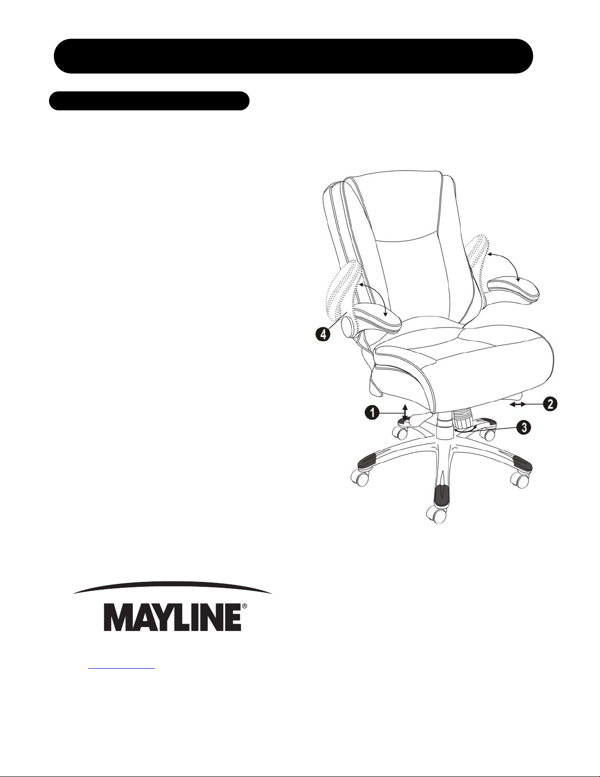
1. To Adjust Seat Height:
While seated, lean forward and reach under the
right side of the chair to find the handle. Lift the
handle and raise your body up slightly to allow the
chair to rise to the desired height. T o lower the seat,
lift the handle while applying more weight
downward on the seat. The chair will descend until
the handle is released or the chair reaches the
bottom position.
2. To Operate Tilt Lockout:
While seated, reach under the left side of the chair
to find the lockout bar. Slide the bar to the left (or to
the outside), all the way out allows the chair to tilt
backwards. To lock the chair in the vertical position,
sit upright and push the bar to the right (or the
center of the chair).
3. To Adjust Tension on The Tilt
Mechanism:
Reach under the front center of the chair, grasp the
round knob and turn counter - clockwise to make the
tilt mechanism firmer (stiffer). To loosen the tilt
mechanism, turn the knob clockwise until the desired
resistance is felt.
4. Adjustable Arms:
This chair has an adjustable arm function so the
arms can be pushed up or pulled down. The arms
can be pushed up next to the back cushion so the
chair can easily roll under a desk.
619 N. Commerce St, PO Box 728, Sheboygan, WI 53082-0728
www.mayline.com 800-822-8037 Fax 920-457-7388
Item number: UL650HBLK
Page 2
EXECUTIVE HI-BACK CHAIR
PARTS LIST
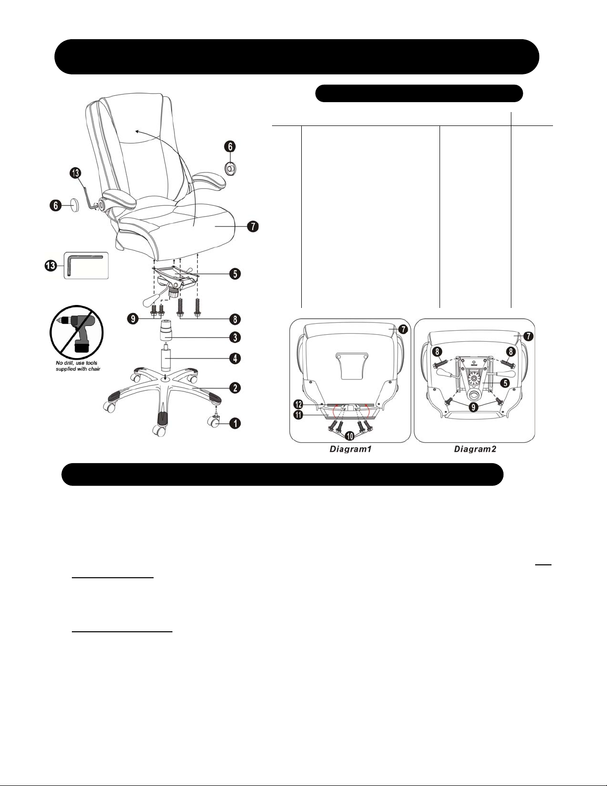
A. Remove all parts from carton and separate them into part number groups as indicated in parts list.
B. To begin assembly, place 5 star base (2) upside down and insert the casters (1) into bottom of the base (2).
C. Turn base (2) right side up on the floor and insert the gas lift (4) into center hole on the 5 star base (2).
D. Place telescoping cover (3) over the gas lift (4) and rest it on the base (2 ).
E. Push the back cushion up to a vertical position, and then put the chair on the floor as shown in Diagram 1. Lift up the
back flap (11), use 1-1/ 4” screws (10) to fasten the bac k support plat e (12) to the bot tom of seat c ushion (7) and
tighten the screws, refer to Diagram 1.
F. Pull the back flap (11) tightly and attach the back flap (11) to the touch fastener on the bottom of seat cushion (7).
G. Attach the seat plat e (5) onto t he bottom of seat cushi on (7)(wit h front of seat plate f acing fro nt of seat cus hion) by
screwing 2-1/4” screws (8) into the front holes of seat plate (5) and 1” screws (9) into the rear holes of seat plate (5)
and tighten the screws, refer to Diagram 2.
H. Place the pre-assembled seat and back cushions w /arms (7) and seat plate (5) on top of gas lift (4) and press down
until fully engaged.
I. Tighten the screws on the arm to back by using the wrench (13), and then put the plastic covers (6) in the arm holes.
J. Periodically (every 90 days) make sure that the screws are still fully tightened.
ATTENTION: Make certain all screws are fully tightened before using chair.
Item # Description Quantity Part #
1.
Casters
2.
5 Star Base
3.
Telescoping Cover
4.
Gas Lift
5.
Seat Plate
6
Plastic Covers
7.
Pre-assembled Seat and Back
Cushions w /arms
8.
2-1/4” Screws
9.
1” Screws
10.
1-1/4” Screws
11.
Back Flap
12.
Back Support Plate
13.
Wrench
H.
Hardware Pack
5
1
1
1
1
2
1
2
2
4
1
1
1
1
11625
11709
11626
11708
11601
H
11710**
H
H
H
~
~
H
11711
Item number: UL650HBLK
 Loading...