

Page 1
O
EXECUTIVE HIGH BACK EZ CHAIR
PERATING INSTRUCTIONS
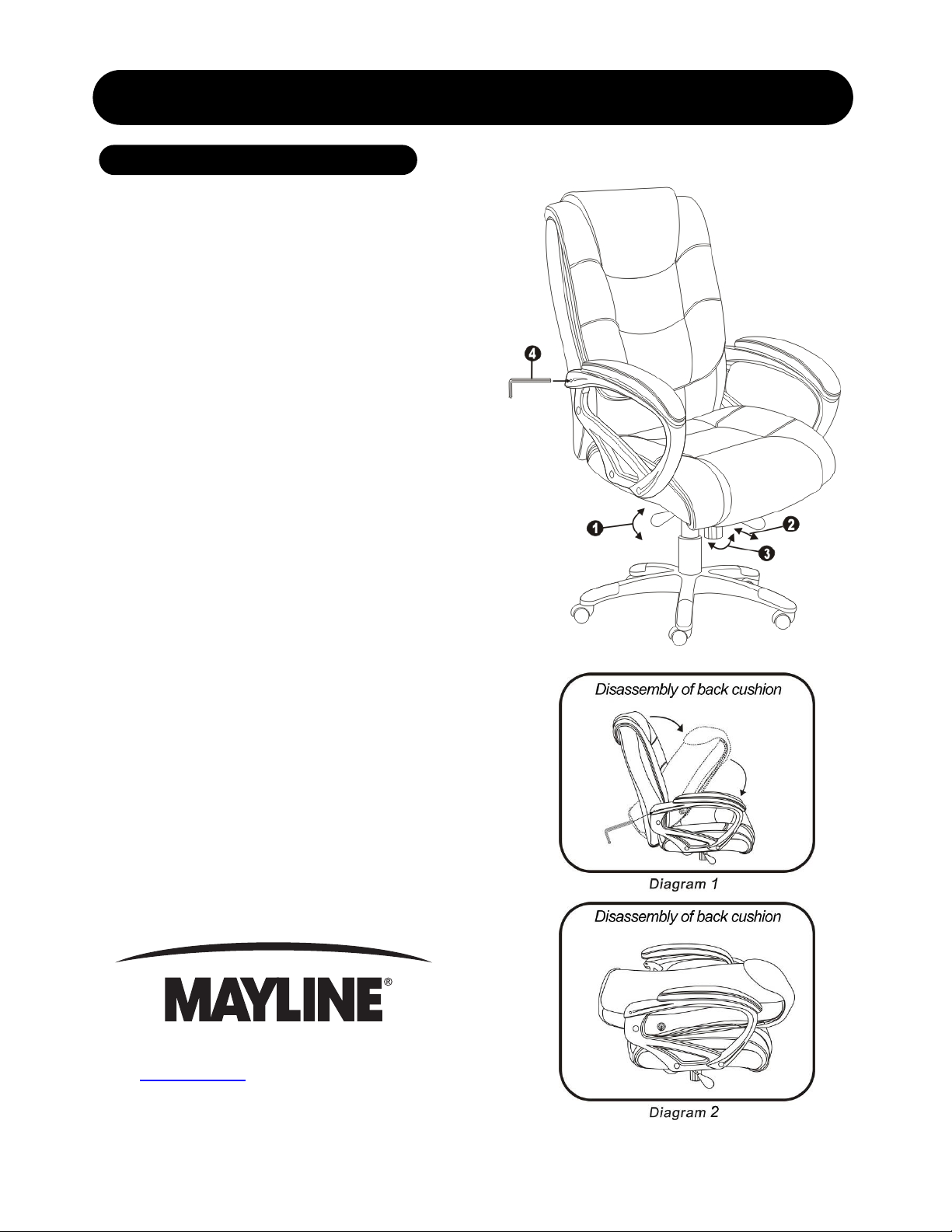
1. To Adjust Seat Height:
While seated, lean forward and reac h under the right
side of the chair to find the handle. Lift the handle and
raise your body up slightly to allow the chair to raise to
the desired h eight. To lower the seat, lift the han dle
while applying weight downward on the seat. The chair
will descend until the handle is released or the chair
reaches the bottom position.
2. To Operate Tilt Lockout:
While seated, reach under the left side of the chair to
find the lockout handle. Pull the handle out of the locked
position which allows the chair to tilt backwards. T o lock
the chair in the vertical position, sit upright and push the
handle in (or towards the center of the chair).
3. To Adjust Tension On The Tilt
Mechanism:
Reach under the front center of the chair, grasp the
round knob and turn counter - clockwise to make the tilt
mechanism firmer (stiffer). To make the tilt mechanism
less firm, turn the knob clockwise until the desired
resistance is found.
4. To Disassemble The Back Cushion:
Standing behind the chair, insert a wrench end (4) into
arm hole position on both sides of the arms to release
the pins. Both pins must be disengaged at the same
time. Push the back cushion forward and fold the back
cushion on seat cushion. (Refer to Diagram 1 and
Diagram 2 for proper disassembly)
619 N. Commerce St, PO Box 728, Sheboygan, WI 53082-0728
www.mayline.com 800-822-8037 Fax 920-457-7388
Item number: UL550HEZBLK
Page 2
EXECUTIVE HIGH BACK EZ CHAIR
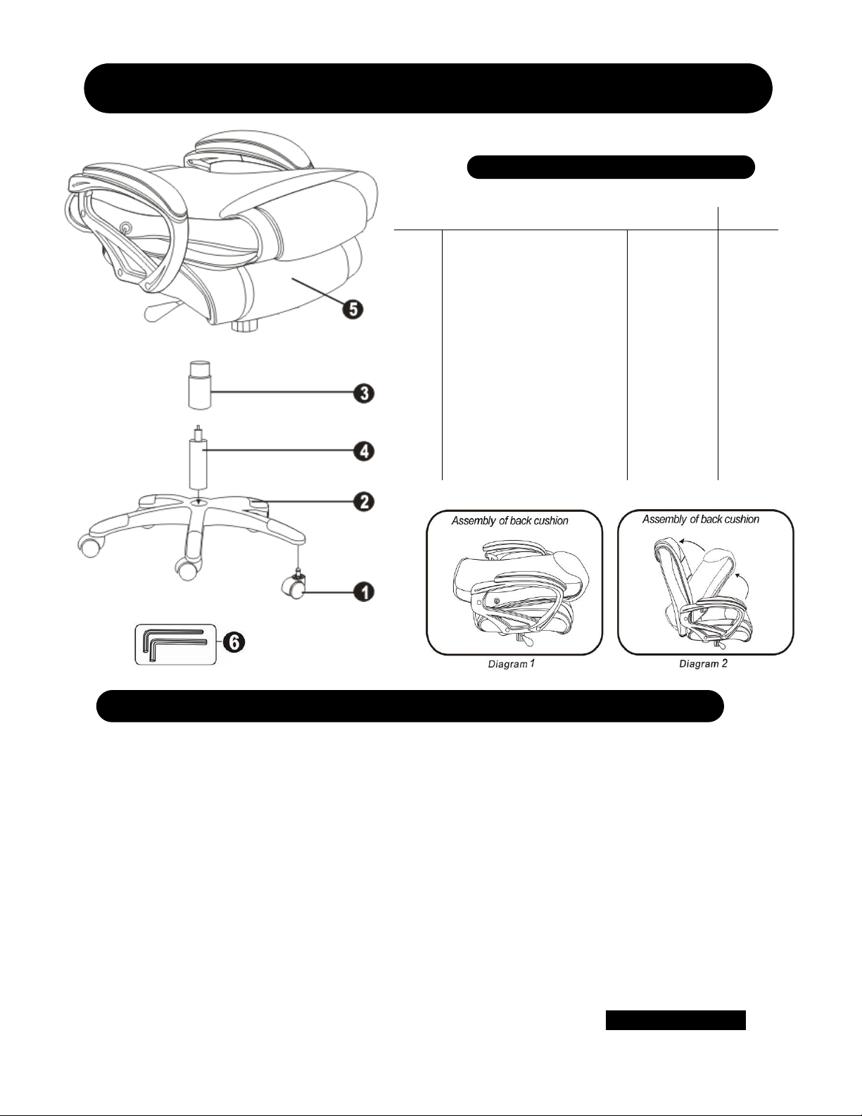
PARTS LIST
Item # Description Quantity Part #
1
2
3
4
5
6
~
Casters
5 Star Base
Telescoping Cover
Gas Lift
Seat and Back C us h i on s
w/Arms & Seat Plate
Wrenches (Attached to seat
cushion bottom)
Pre-assembl ed S e at P l ate
1
5
1
1
1
1
2
11625
11673slt
11626
11708
11692**
~
11601
A. Remove all parts from carton and separate them into part number groups as indicated in the parts list.
B. To begin assembly, place the 5 star base (2) upside down and insert the casters (1) into bottom of the base (2).
C. Turn the base (2) right side up on the floor and insert the gas lift (4) into center hole on the base (2).
D. Place the telescoping cover (3) over the gas lift (4) and rest it on the base (2).
E. Place the seat and back cushions with arms and seat plate (5) on top of gas lift (4) and press down until fully
engaged.
F. Standing in front of the chair, push the back cushion into an upright position. Check to make sure the pins have
locked into the arm holes correctly. (Refer to Diagram 1 and Diagram 2 for proper assembly)
G. Periodically (every 90 days) make sure that the screws are still fully tightened.
ATTENTION: Make certain all screws are fully tightened before using chair.
U.S. Patent: D542,578
Item number: UL550HEZBLK
 Loading...