

Page 1
MANAGERIAL MID-BACK CHAIR
S
OPERATING INSTRUCTION
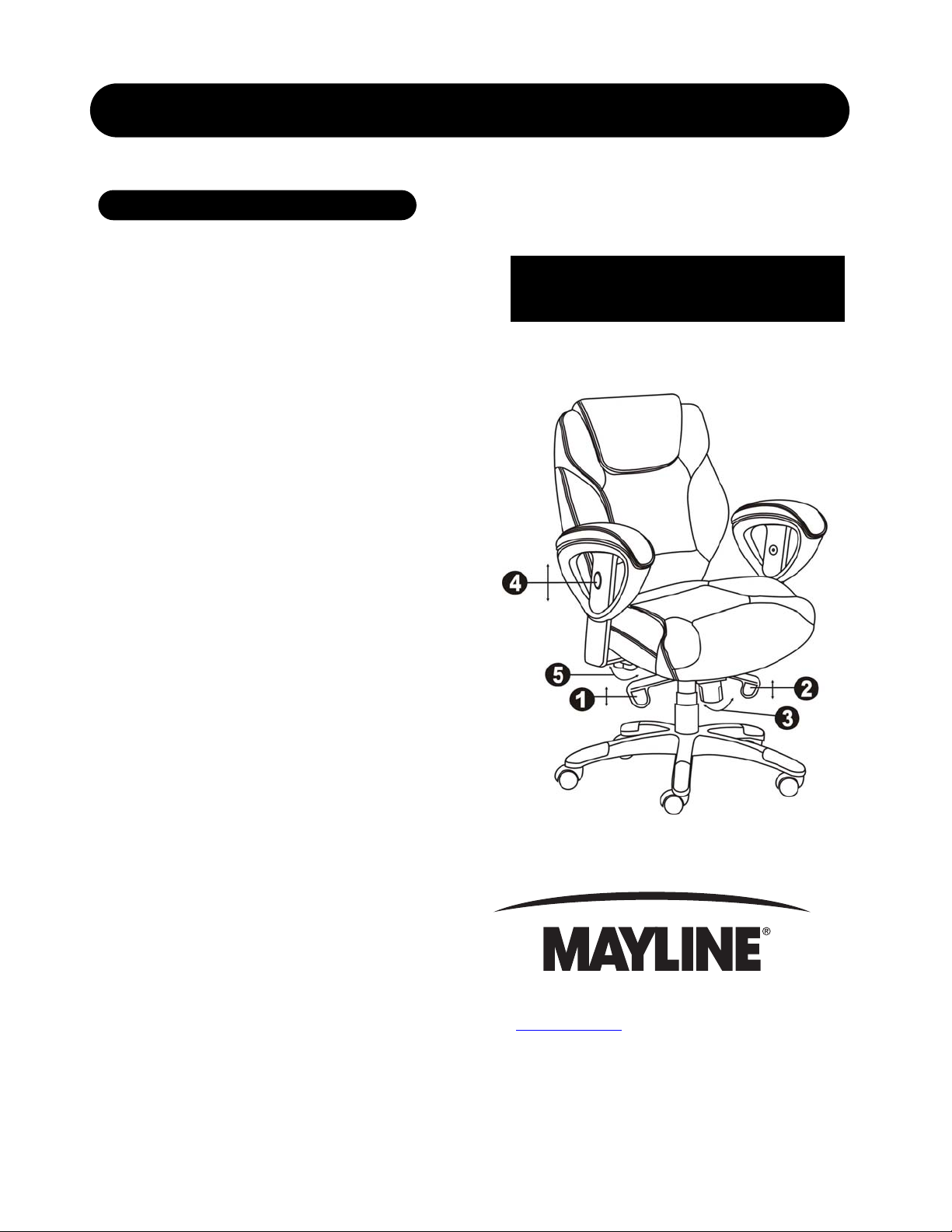
1. To Adjust Seat Height:
While seated, lean forward and reach under right side
of the chair to find the lever. Push lever upward and
raise your body up slightly to allow the chair to rise to
the desired height. To lower the seat, push lever
upward and apply weight downward on the seat. The
chair will descend until the lever is released or the
chair reaches the lowest position available.
CP-240 arm U.S. Patent D494,791S
CP-465 arm pad U.S. Patent D538,560S
2. To Operate Synchro Lockout:
Reach under left side of the c ha i r t o f i nd th e lever. Push
lever upward to allow the chair to tilt backwards. To lock
the back and seat in the positions you desire, turn lever
downward. Once you want to release the synchro
mechanism from the lock position, push the lever upward
(when pushing the lever upward, apply more weight
backward onto the back rest cushion and then release,
the back rest cushion will return back to normal position.).
3. To Adjust Tension on The Tilt:
Reach under the front center of the chair, grasp the round
knob and turn it counter - clockwise to stiffen the tilt
mechanism. Turn the knob clockwise to loosen the tilt
mechanism. Rotate the knob until the desired resistance
is reached.
4. To Adjust Arm Height:
Press the buttons on the chair arms. Press the buttons
to allow the arms to move up or down freely then
release the buttons once the desired height is reached.
5. To Adjust Arm Width:
While seated , reach for the knobs und erneath the
arms located on bottom of seat cushion. Turn the
knobs clockwise to loosen the width adjustment feature
then turn the knobs counter - clockwise to tighten
when you have reached your desired width.
619 N. Commerce St, PO Box 728, Sheboygan, WI 53082-0 728
www.mayline.com 800-822-8037 Fax 920-457-7388
Item number: UL330MBLK/UL330MBUR
Page 2

MANAGERIAL MID-BACK CHAIR
PARTS LIST
Item # Description Quantity Part #
1.
2.
3.
4.
5.
6A.
6B.
7.
8.
9.
10.
11.
12.
13.
H
Casters
5 Star Base
Telescoping Cover
Gas Lift
Seat Plate
Left Arm
Right Arm
Seat Cushion
Back Cushion
1-1/4” Screws
1/2” Screws
Back Support Plate
attached to the back cushion)
Knobs
Wrench
Hardware Pack
(already
5
1
1
1
1
1
1
1
1
4
3
1
2
1
1
11625
11673slt
11626
11708
11706
11698**
11698**
11690**
11683**
H
H
~
101724
H
11704
A. Remove all parts from carton and separate them into part number groups as indicated above.
B. To begin assembly, place 5 star base ( 2 ) ups i de d ow n and insert cast er s ( 1) i n t o bottom of base (2) .
C. Turn base (2) right side up on the floor and insert gas lift (4) into center hole on base (2).
D. Place telescoping cover (3) over the gas lift (4) and rest it on the base (2).
E. Attach seat pla te (5) onto the underneath of seat cushion (7) (with front of seat plate facing fron t of seat cushion)
by screwing 1-1/4” screws (9) into the seat plate (5) and tighten screws.
F. Insert the back support plate (11) into the bracket of seat plate (5), line up the holes on both back support plate (11)
& bracket of seat plate (5), secure with 1/2” screws (10) as shown in diagram 1 and tighten screws.
G. Place the assembled chair on top of gas lift (4) and press down until fully engaged.
H. Take off the knobs (12) from the arm brackets (6A & 6B), insert the arm brackets (6A & 6B) into the sockets on the
bottom of seat cushion (7) and fastened by using the knobs (12).
I. Periodically (every 90 days) tighten all screws in the chair.
ATTENTION: Make certain to tighten all screws before using chair.
Diagram 1
Item number: UL330MBLK/UL330MBUR
 Loading...