

Page 1
EXECUTIVE MID-BACK CHAIR
OPERATING INSTRUCTIONS
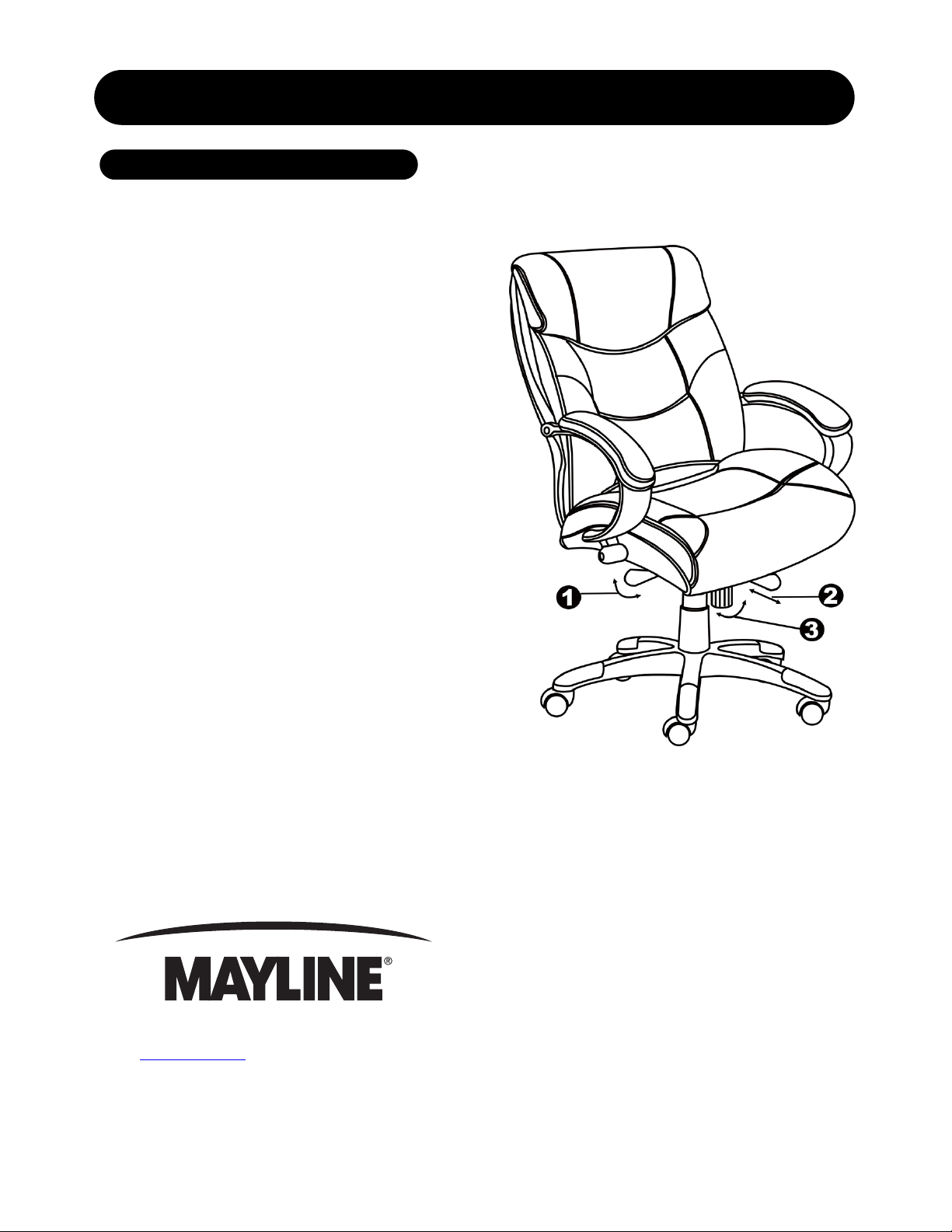
1. To Adjust Seat Height:
While seated, lean forward and reach under the
right side of the chair to find the handle. Lift the
handle and raise your body up slightly to allow the
chair to raise to the desired height. To lower the
seat, lift the handle while applying more weight
downward on the seat. The chair will descend until
the handle is released or the chair reaches the
bottom position.
2. To Operate Tilt Lockout:
While seated, reach under the lef t side of the chair
to find the lockout bar . Slide the bar to the lef t (or to
the outside), all the way out allows the ch air to tilt
backwards. To lock the chair in the vertical
position, sit upright and push the bar to the right
(or the center of the chair).
3. To Adjust Tension on The Tilt
Mechanism:
Reach under the front center of the chair, grasp
the round knob and turn counter - clockwise to
make the tilt mechanism firmer (stiffer). To loosen
the tilt mechanism, turn the knob clockwise until
the desired resistance is felt.
619 N. Commerce St, PO Box 728, Sheboygan, WI 53082-0728
www.mayline.com 800-822-8037 Fax 920-457-7388
Item number: UL230MBLK / UL230MBUR
Page 2
EXECUTIVE MID-BACK CHAIR
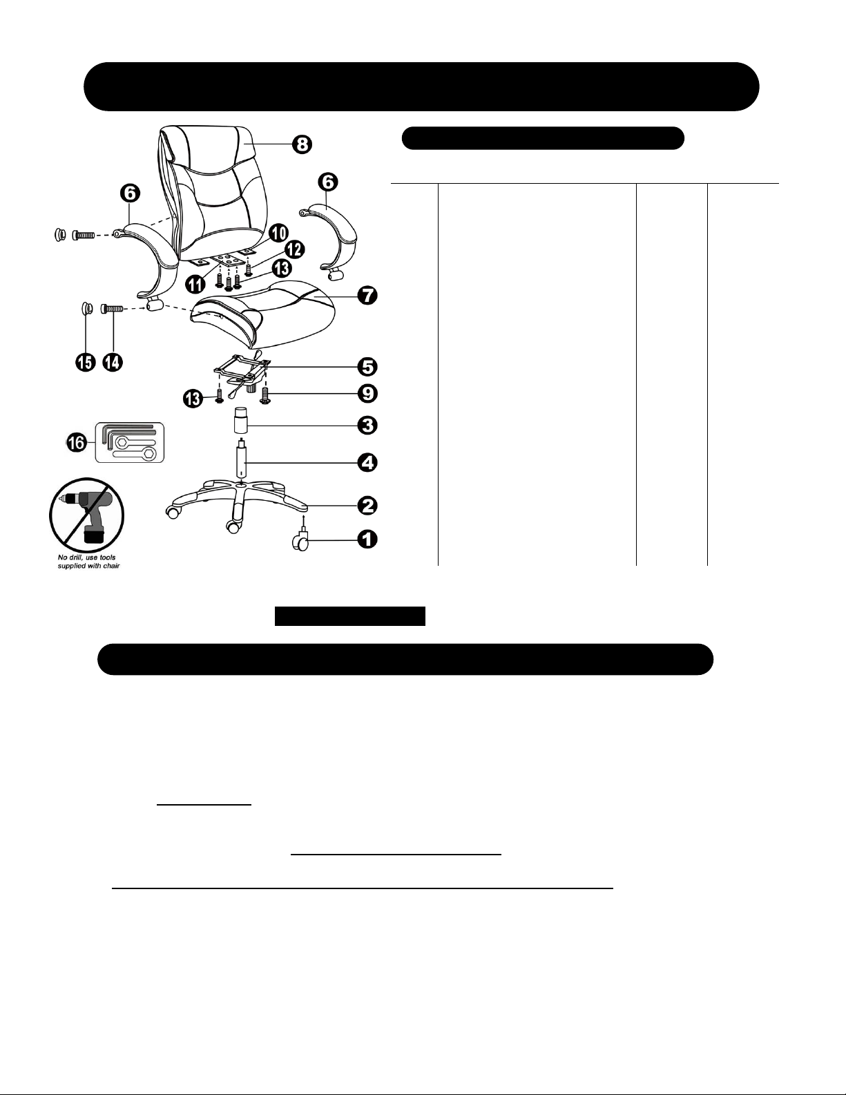
PARTS LIST
Item # Description Quantity Part #
1.
2.
3.
4.
5.
6.
7.
8.
9.
10.
11.
12.
13.
14.
15.
16.
H.
Casters
5 Star Base
Telescoping Cover
Gas Lift
Seat Plate
Arms
Seat Cushion
Back Cushion
1-1/2” Big Screws
Small Back Support Plates
(already attached to the back
cushion)
Large Back Suppor t P l ate
(already attached to the back
cushion)
1-1/4” Small Screws
1-1/4” Big Screws
2-1/2” Big Screws
Black Plastic Caps
Wrenches
Hardware Pack
5
1
1
1
1
2
1
1
2
2
1
2
6
4
4
4
1
11625
11624
11626
11708
11601
11697**
11689**
11682**
H
~
~
H
H
H
H
H
11703
U.S. Patent: D474,052S
A. Remove all parts from carton and separate them into part number groups as indicated in parts list.
B. To begin assembly, place the 5 star base (2) upside down and insert the casters (1) into bottom of the base (2).
C. Turn the base (2) right side up on the floor and insert the gas lift (4) into center hole on the base (2).
D. Place the telescoping cover (3) over the gas lift (4) and rest it on the base (2).
E. Attach seat plate (5) to the bottom of seat cushion (7) (with front of seat plate facing fron t of seat cushion) by using
1-1/2” big screws (9) into the front holes of seat plate (5) and 1-1/4” big screws ( 13) into the rear holes of seat plate
(5) and tighten screws.
F. Align the back cushion (8) with seat cushion (7) and attach the two small back support plates (10) to seat cushion
(7) by using 1-1/4” small screws (12), then using 1-1/4" big screws (13) attach the large back support plate (11) to
the bottom of seat cushion (7). Do not tighten screws completely.
G. Insert 2-1/2" big screws (14) into arm holes attaching arms (6) to sides of seat cushion (7) and back cus hion (8).
Now, tighten all the screws. Remember to tighten screws on back support plates!
H. Place the assembled chair on top of gas lift (4) and press down until fully engaged.
I. Place black plastic caps (15) into arm holes once screws have been tightened.
J. Periodically (every 90 days) make sure that the screws are still fully tightened.
ATTENTION: Make certain to fully tighten all screws before using chair.
Item number: UL230MBLK / UL230MBUR
 Loading...