

Maykke Winston, YSA1432101 Installation Manual
WINSTON LINEN TOWER
PRODUCT INSTALLATION
MODEL: YSA1432101
LIMITED LIFETIME WARRANTY
WHAT IS COVERED
All products in the package carry a One-Year Limited Lifetime warranty. This warranty applies only to the original
purchaser and to the original installation of the product.
WHAT IS NOT COVERED
Damage caused during moving or during installation is not a defect or warranty issue and will not be considered as such.
This warranty does not cover product failure caused by abusive treatment, surface scratches, misuse, neglect or damage
due to handling or faulty installations. All wood naturally ages, darkens, changes in color, and mellows over time due
to exposure to light. While this color change is imperceptible from day to day
time, or due to amount of light the wood is exposed to. Imperfections such as small surface splits, small dark holes or
darker mineral streaks are natural and are not considered defects.
PRE-INSTALLATION
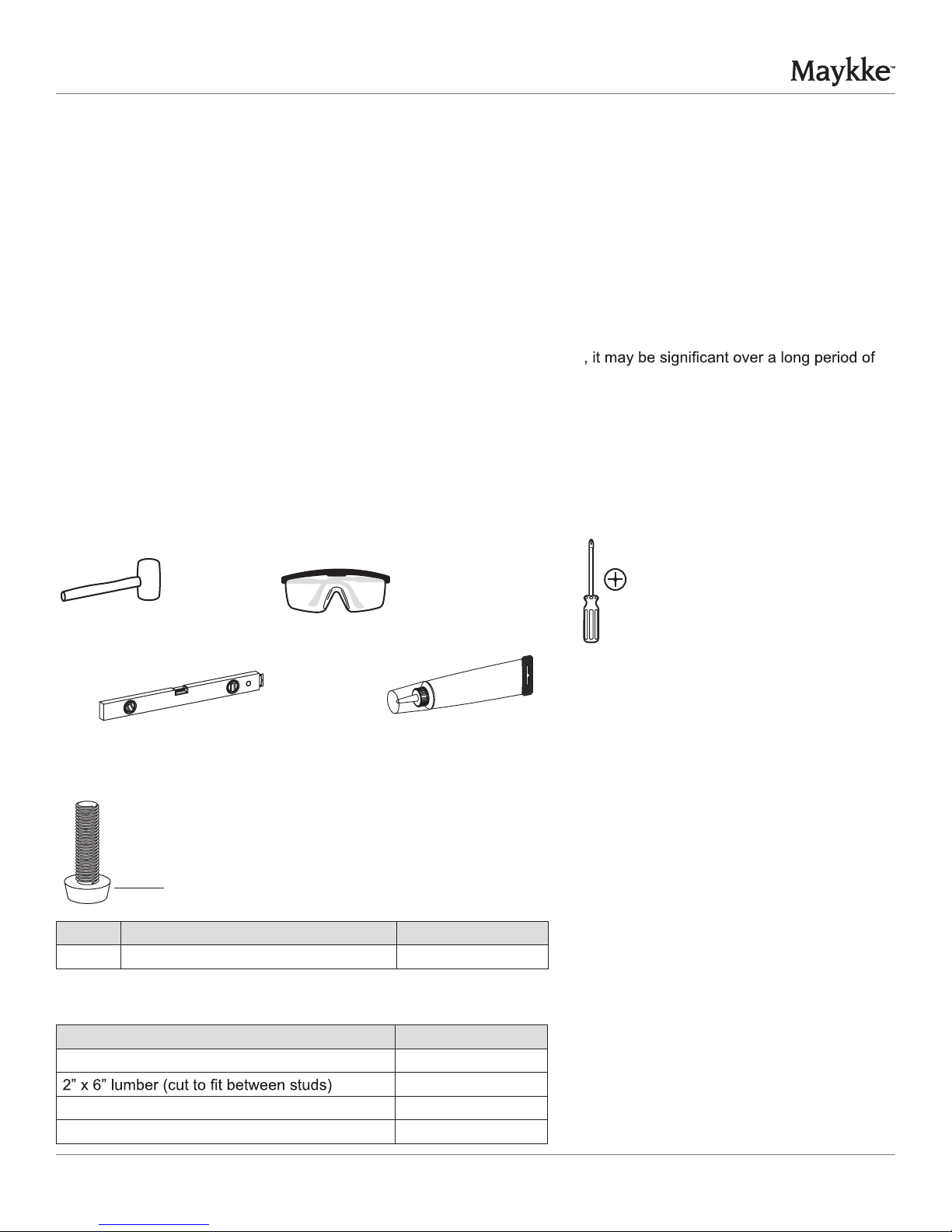
Tools Required
Rubber mallet Safety goggles
Level
Hardware Included
AA
Part Description Quantity
AA Leg levelers (pre-installed on legs) 4
Materials Required
Phillips
screwdriver
Silicone
Compound
Description Quantity
Wood screws 2
5/16” Lag Bolts (min. 250lbs) load bearing 2
Washers for Lag Bolts 2
PRODUCT INSTALLATION
1
1
REV 111715
WINSTON LINEN TOWER
PRE-INSTALLATION (continued)
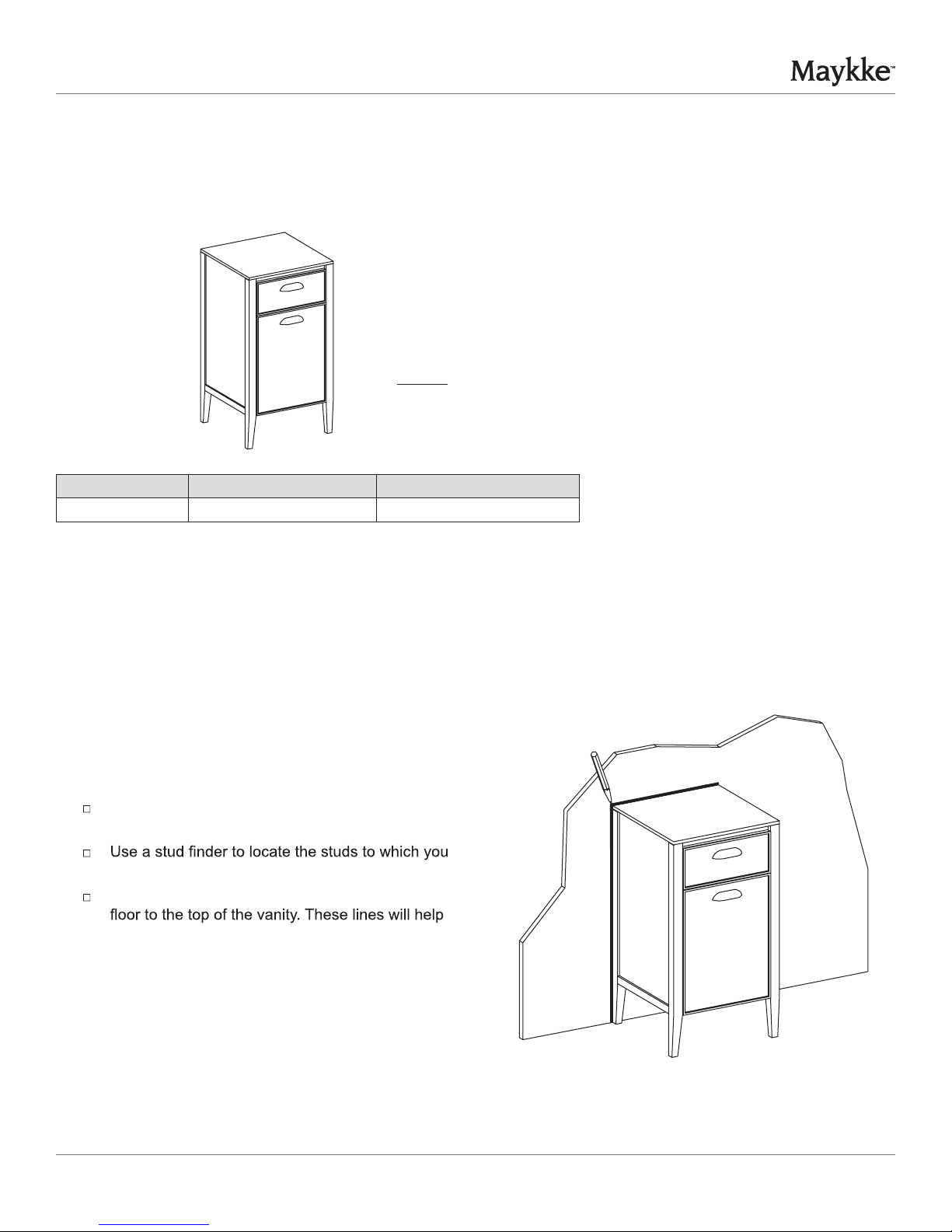
Package Contents
Part Description Quantity
A Cabinet body 1
PRODUCT INSTALLATION
A
INSTALLATION
1
Determine the ideal location for your new bath furniture.
Tracing the outline of the vanity
If placing the side cabinet along the wall, then trace
its outline on the wall.
will attach the vanity.
With a level, draw lines along the studs from the
you spot where to place the screws in Step 3.
PRODUCT INSTALLATION
2
REV 111715
WINSTON LINEN TOWER
INSTALLATION (continued)
PRODUCT INSTALLATION
2
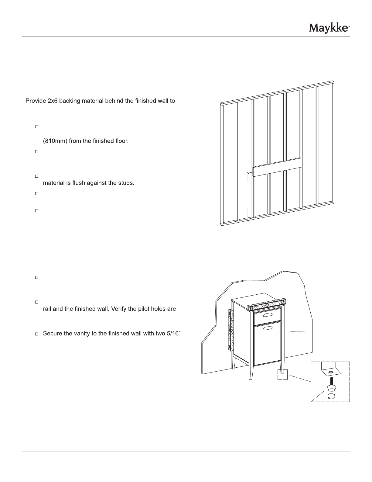
properly support the vanity.
Installing support for vanity
To properly secure the vanity, the middle of the
required 2x6 backing material must be 31-7/8”
Extend the backing material beyond the width of the
vanity to the nearest stud. This will ensure proper
support for the vanity.
Front-notch the studs to ensure the 2x6 backing
Secure the 2x6 backing material to the studs with
framing nails.
Rough-in the water supply and drain lines into the
rough-in plumbing areas of the vanity.
3 Attaching the vanity
2”x6” backing material
31-7/8” (810mm)
Verify the vanity is level and back rail is plumb
against the wall. If necessary, turn the leg levelers
(AA) to adjust the vanity.
Using drill bit, drill two pilot holes through the back
positioned to ensure the lag bolts will engage the
2x6 backing material.
lag bolts and washers (not provided).
A
AA
PRODUCT INSTALLATION
3
REV 111715
 Loading...