

MAYEKAWA 4M, 6M, 8M Operation Manual
2202G1JE-DA-M-N_2010.01.
Third Edition 2010/1/5
Reciprocating Compressor
M Series Operation Manual
4M/6M/8M/62M/62M-FM
CAUTION
Before operating, inspecting, or servicing the compressor, read this manual thoroughly to fully
understand the contents.
Keep this operation manual in a safe, designated place for future reference whenever the
manual is needed.
3–14–15 Botan Koto-ku, Tokyo 135-8482, Japan


2202G1JE-DA-M-N_2010.01.
Preface
Thank you for having purchased our M series reciprocating compressor (hereinafter indicated as "this
machine").
This operation manual (hereinafter indicated as "this manual") describes safety information, operational and
maintenance procedures in detail for safe and effective use of this product.
Before installing or using this product, make sure you read this manual.
Keep this manual in a safe place near the product for quick reference.
Preface
Reciprocating Compressor M Series
i

2202G1JE-DA-M-N_2010.01.
Warranty and Disclaimer
Warranty and Disclaimer
Warranty Clauses
If malfunctions or damages occur under proper usage (conditions) following documents such as operation
manual or drawings of this product, or, if MAYEKAWA judges that malfunctions or damages are related to
design or manufacture of the product, and if the malfunctions or damages are within the warranty period, we
will repair or replace the product without any charges.
The warranty period is "12 months from factory shipment of this product".
MAYEKAWA is not liable for production or man made disaster compensation due to malfunction or damage
of this product.
Disclaimer Clauses (Exclusion of Warranty Clauses)
Although MAYEKAWA warrants the clauses mentioned above, the following clauses are exempted.
Malfunction or damage of this product caused by natural disaster, or other accidental forces (such as
fire, thunderbolt, windstorm, intense rainfall, flood, tidal wave, earthquake, land subsidence, e.t.c).
Malfunction or damage caused by misusage described below.
Malfunction, damage, or defect of this product due to abnormal or improper use (such as storing
this product for middle to long term outside the building or in locations subject to high
temperatures and high humidity, unexpected inspections, tests, operations, and excessive repetition
start-up/stoppage of the product.)
Malfunction or damage caused by devices or equipments not provided by MAYEKAWA including
operation control methods of those devices.
Malfunction or damage caused by refrigerants, gases, or refrigerant oils, and operating conditions
(design conditions) not approved for this product.
Malfunction or damage caused by maintenance or inspection not recommended by MAYEKAWA.
Malfunction or damage caused by parts that are not Mayekawa genuine.
Malfunction or damage caused by remodeling the product without approval of MAYEKAWA.
Malfunction or damage caused by unexpected misusage
Reciprocating Compressor M Series
ii

2202G1JE-DA-M-N_2010.01.
Important Information
Important Information
Intended Use of the Product
This product is a universal screw compressor intended for refrigeration, cold storage, and air conditioning. Do
not use the product for any other purposes that are not intended for or which depart from the specifications.
For specifications of this product, refer to "2.2 Compressor Specifications".
When performing maintenance use qualified refrigeration personnel.
Important Information for Safe Use of the Product
Although MAYEKAWA has paid a lot of attention to safety measures for this product, all hazards including
potential hazards caused by human errors, or due to environmental conditions can not be anticipated.
There are guidelines that must be observed for operating this product. However, the warnings in this manual
and safety labels on the product are not all inclusive. When operating this product, pay extreme caution on
personnel safety as well as on items described in this manual.
Important rules for safety work with the product that apply to all workers including managers and supervisors
are listed below.
Before using this product, carefully read and fully understand the contents written in this manual and pay
attention to safety.
Operation, maintenance, and inspection of this product should be performed by qualified personnel
educated about the fundamentals of the product and trained about hazards involved and measures to
avoid danger.
Do not allow any person other than those educated on the fundamental expertise of the product and
trained about hazards involved and measures to avoid dangers to approach the product while it is
operating or during maintenance.
Observe all related federal/national and local codes and regulations.
To prevent accidents, do not carry out any operation or maintenance other than those described in this
manual, or use the product for any unapproved purpose.
Replace the parts with the
Not only workers but also managers should actively participate safety and health activities in the
workplace to prevent accidents.
Observe the following precautions when performing maintenance work on electrical control.
Electrical maintenance of the product must be performed by certified/qualified personnel and only those
educated about the electrical control of the product.
Before servicing or inspecting the electrical equipments or devices, turn "OFF" the motor main power
and control power, and perform lockout/tagout to prevent the power from being turned on during work.
Even when the motor main power and control power are turned "OFF", the product may be turned on if the
power is supplied from outside the refrigeration system, cold storage, and air conditioning system. Make sure
the power supply on the power source side is shut off, and perform lockout/tagout to prevent the product from
being turned on during work.
genuine parts.
Reciprocating Compressor M Series
iii
2202G1JE-DA-M-N_2010.01.
Important Information
About This Manual
This product may be modified without prior notice. Therefore, the appearance of actual machine may
differ from the descriptions in this manual. If you have any questions contact your sales offices or
service centers.
This manual is in English. If any other language is required it is the customers responsibility to prepare
a manual for safety education and operation instructions.
This manual is copyrighted. Drawings and technical references including this manual shall not, in
whole or part, be copied, photocopied, or reproduced into any electronic medium or machine-readable
form without prior permission from MAYEKAWA.
Photographs or drawings included in this manual may differ from the appearance of actual product.
If this manual is lost or damaged, immediately place a purchase order to your local sales office or
service center for a new manual. Using the product without the manual may result in safety issues.
If you resell the product, never fail to attach this manual to the product.
Construction of This Manual
Title of section and chapter Description details
Preface Describes the outline of this manual and how to read this manual.
Warranty and Disclaimer
Important Information Describes important information related to the machine and this manual.
1. Safety
2. Configuration and
Specification of Compressor
3. Installation Describes the installation procedure of the machine.
4. Operation of the Compressor
and the System
5. Maintenance
6. Troubleshooting
7. Related Document Describes information such as illustrated parts breakdown and parts list.
Describes clauses and coverage of warranty.
Exclusion of warranty clauses is described as disclaimer.
Describes safety information for the worker, safety rules for this machine,
and management details regarding the work safety that is required for
handling the machine.
Describes the main components of the machine, functional information,
specification, and service limits.
Describes the precautions for operating the machine.
Describes sections and period for inspecting, and assembly and
disassembly of this product.
Describes the methods of the machine in case of problem occurring during
operation of the machine.
How to Order Genuine Parts
Confirm the applicable parts in "7.1 Development View and Configuration Table of the Parts" of "Chapter 7,
Related Document". And inform the “Product Name, Part Number, Part Name, and required quantity” to your
local sales offices or service centers.
Reciprocating Compressor M Series
iv
2202G1JE-DA-M-N_2010.01.
Important Information
Inquiry
If you need further information or have any questions, please contact your local sales offices or service
centers.
1. Domestic
Description Address Tel/Facsimile
Head office
Moriya plant
Hokkaido office
Tohoku office
Hokushinetsu
office
Kanto office
Tokai office
Chubu office
Kansai office
Chugoku office
Shikoku office
Kyushu office
2. Overseas
〒135-8482
3–14–15 Botan Koto-ku, Tokyo
〒302-0118
2000, Taysuzawa Moriya-shi, Ibaraki-pref
〒063-0803
2-5-1, 3-jyo Nijuuyonken Nishi-ku, Sapporo-city, Hokkaido
〒983-0012
2-5-12, Ideka, Miyagino-ku, Sendai-shi, Miyagi-pref.
〒950-0925
Oyama-build. 303, 1-2-34, Bentenbashi-dori, Chuo-ku, Niigata-shi,
Niigata-pref.
〒135-8482
3–14–15 Botan Koto-ku, Tokyo
〒422-8034
1-15-36, Takamatsu, Suruga-ku, Shizuoka-shi, Shizuoka-pref.
〒460-0002
2-9-6, Marunouchi, Naka-ku, Nagoya-shi, Aichi-pref.
〒553-0001
1-4-27, Ebie, Fukushima-ku, Osaka-shi, Osaka
〒739-2117
2-3-40, Takayadai, Higashihiroshima-shi, Hiroshima-pref.
〒761-8074
410-1, Otakamimachi, Takamatsu-shi, Kagawa-pref.
〒810-0802
Fukuoka-fujiland-build. 10F, 2-3, Nakajima-cho, Nakasu,
Hakata-ku, Fukuoka-shi, Fukuoka-pref.
TEL:03-3642-8181
FAX:03-3643-7094
TEL:0297-48-1361
FAX:0297-48-5269
TEL:011-631-2052
FAX:011-631-2053
TEL:022-259-5211
FAX:022-259-5223
TEL:025-257-1626
FAX:025-286-6165
TEL:03-3643-2886
FAX:03-3641-8468
TEL:054-236-5350
FAX:054-236-5355
TEL:052-218-3307
FAX:052-218-3308
TEL:06-4795-6000
FAX:06-4795-6033
TEL: 082-491-1830
FAX: 082-491-1838
TEL:087-868-3400
FAX:087-868-3399
TEL:092-262-0016
FAX:092-262-0115
Description Location
NORTH AMERICA
MYCOM CANADA LTD.
(VANCOUVER OFFICE)
MYCOM CANADA LTD.
(TORONTO OFFICE)
MAYEKAWA U.S.A. INC.
(HEAD OFFICE)
MAYEKAWA U.S.A. INC.
INDUSTRIAL REFRIGERATION
DIVISION (MIAMI OFFICE)
MAYEKAWA U.S.A. INC.
INDUSTRIAL REFRIGERATION
DIVISION (CHARLOTTE OFFICE)
Reciprocating Compressor M Series
UNIT 110, 6620 MCMILLAN WAY,
RICHMOND, B.C., V6W 1J7, CANADA
1745 BONHILL ROAD,
UNIT #6&7 MISSISSAUGA,
ONTARIO, L5T 1C1, CANADA
8750 WEST BRYN MAWR AVENUE,
SUITE 190 CHICAGO, IL 60631, U.S.A.
7220 N.W. 32TH AVE., SUITE 303,
MIAMI, FL 33166, U.S.A.
15905 BROOKWAY DRIVE UNIT 4208
HUNTERSVILLE, NC 28078, U.S.A.
Telephone and
facsimile No.
TEL: (1) 604-270-1544
FAX: (1) 604-270-9870
TEL: (1) 905-564-0664
FAX: (1) 905-564-7614
TEL: (1) 773-516-5070
FAX: (1) 773-516-5071
TEL: (1) 305-477-5741
FAX: (1) 305-477-5681
TEL: (1) 704-896-3632
FAX: (1) 704-896-3697
v

2202G1JE-DA-M-N_2010.01.
Important Information
Description Location
MAYEKAWA U.S.A. INC.
INDUSTRIAL REFRIGERATION
DIVISION (NASHVILLE OFFICE)
MAYEKAWA U.S.A. INC.
INDUSTRIAL REFRIGERATION
DIVISION (LA OFFICE, FACTORY)
MAYEKAWA U.S.A. INC.
INDUSTRIAL REFRIGERATION
DIVISION (SEATTLE OFFICE)
MAYEKAWA U.S.A. INC.
INDUSTRIAL REFRIGERATION
DIVISION
(MODESTO OFFICE)
MAYEKAWA U.S.A. INC.
INDUSTRIAL REFRIGERATION
DIVISION
(SAN FRANCISCO OFFICE)
MAYEKAWA U.S.A.INC.
INDUSTRIAL REFRIGERATION
DIVISION (SAN ANTONIO OFFICE)
MAYEKAWA U.S.A. INC.
INDUSTRIAL REFRIGERATION
DIVISION (NY OFFICE)
MAYEKAWA U.S.A. INC.
INDUSTRIAL REFRIGERATION
DIVISION (YORK OFFICE)
MAYEKAWA U.S.A.INC.
MANUFACTURING DIVISION
(SAN ANTONIO OFFICE, FACTORY)
MAYEKAWA U.S.A. INC.
CHEMICAL PROCESS DIVISION
MAYEKAWA U.S.A. INC.
CHEMICAL PROCESS DIVISION
(HUSTON OFFICE)
EUROPE
N.V.MAYEKAWA EUROPE S.A.
(HEAD OFFICE, FACTORY)
N.V.MAYEKAWA EUROPE S.A.
ZWEGNIEDEALASSUNG
DEUTSHLANSD
MAYEKAWA UK REPRESENTATIVE
OFFICE
MAYEKAWA. S.L. CALLE MONTEVIDEO 5, NAVE 13 POL.
MAYEKAWA EUROPE S.A.
SUCCURSALE FRANCAISE
MAYEKAWA MFG. CO., LTD.
MOSCOW LIAISON OFFICE
MYCOM INTERTEC AG ROSENBERGSTRASSE 31, CH-6300 ZUG,
MAYEKAWA EUROPE S,A,
DUBAI OFFICE
MAYEKAWA BULGARIA
REPRENSETATIVE OFFICE
MYCOM REFRIGERATION
INDIA PVT.LTD.
MAYEKAWA AUSTRALIA
PTY.LTD.
SUITE 203 BROOKSIDE LANDING
1550 N MT JULIET RD.,
MT JULIET, TN 37122, U.S.A
19475 GRAMERCY PLACE,
TORRANCE, CA 90501, U.S.A.
2615 W CASINO ROAD, UNIT-3D,
EVERETT, WA 98204, U.S.A.
4718 GREEN LEAF COURT,
SUITE 5 MODESTO, CA 95356, U.S.A.
1840 GATEWAY DRIVE, # 226 SAN MATEO,
CA 94404, U.S.A.
16825 IH 35 NORTH SELMA,
TX 78154, U.S.A.
303 SOUTH BROADWAY,
SUITE 102 TARRYTOWN,
NEW YORK 10591, U.S.A.
3395 FARMTRAIL ROAD YORK,
PA 17406, U.S.A.
16825 IH 35 NORTH SELMA,
TX 78154, U.S.A.
19475 GRAMERCY PLACE,
TORRANCE, CA 90501, U.S.A.
3222 PASADENA FREEWAY PASADENA,
TX 77503, U.S.A.
LEUVENSESTEENWEG 605,
1930 ZAVENTEM, BELGIUM
NUERNBERGER STRASSE 118,
97076 WUERZBURG, DEUTSCHLAND
16 OAKHURST GARDENS, BEXLEYHEATH,
KENT DA7 5JP, UNITED KINGDOM
INDUSTRIAL CAMPORROSO 28806 ALCALA
DE HENARES, MADRID, SPAIN
9, RUE MICHAEL FARADAY, 78180
MONTIGNY-LE-BRETONNEUX, FARNCE
HOUSE 3, FLAT 54, MYTNAYA ST,
MOSCOW, 119049 RUSSIA
SWITZERLAND
P.O.BOX.61349, LOB.11.NO.126,
JEBEL ALI FREE ZONE, DUBAI, U.A.E.
94, HRISTO BOTEV STR. 1202, SOFIA,
BULGARIA
#30 CENTRUM PLAZA,
GOLF COURESE ROAD, SECTOR 53,
GURAGAON, HARYANA, 122002,
REPBLIV OF INDIA
UNIT 2, 44 MCCAULEY STREET
MATRAVILLE NSW 2036, AUSTRALIA
Telephone and
facsimile No.
TEL: (1) 615-773-2859
FAX: (1) 615-758-7743
TEL: (1) 310-328-1362
FAX: (1) 310-782-6759
TEL: (1) 425-348-3404
FAX: (1) 425-348-3419
TEL: (1) 209-545-9752
FAX: (1) 209-545-3654
TEL: (1) 650-378-1235
FAX: —
TEL: (1) 210-599-4536
FAX: (1) 210-599-4538
TEL: (1) 914-301-9770
FAX: (1) 914-332-0400
TEL: (1) 717-779-0138
FAX: (1) 717-779-0109
TEL: (1) 210-599-4518
FAX: (1) 210-599-1788
TEL: (1) 310-328-6279
FAX: (1) 310-328-8487
TEL: (1) 281-447-2599
FAX: (1) 281-447-6623
TEL: (32) 2-757-9075
FAX: (32) 2-757-9023
TEL: (49) 931-389388-0
FAX: (49) 931-359388-20
TEL: (44) 1322-433558
FAX: (44) 1322-433164
TEL: (34) 91-830-0392
FAX: (34) 91-830-0397
TEL: (33) 1-30-58-26-00
FAX: (33) 1-30-58-19-37
TEL: (7) 499-230-01-76
FAX: (7) 495-230-21-12
TEL: (41) 41-726-8626
FAX: (41) 41-726-8620
TEL: (971) 4-887-2232
FAX: (971) 4-887-2238
TEL: (359) 2-8319002
FAX: (359) 2-8319002
TEL: (91) 12-4420-6616
FAX: (91) 12-4420-6618
TEL: (61) 2-9695-7000
FAX: (61) 2-9695-7001
Reciprocating Compressor M Series
vi
2202G1JE-DA-M-N_2010.01.
Important Information
Description Location
MAYEKAWA AUSTRALIA PTY.
LTD.(NEW ZEALAND BRANCH)
ASIA
P.T.MYCOM INDONESIA GRAHA PRATAMA BUILDING, 9TH FLOOR
MAYEKAWA (M) SDN. BHD. 35-1, BLOCK D1, DATARAN PRIMA,
MYCOM PHILIPPINES CORP. UNIT 2706 UNION BANK PLAZA
MYCOM PHILIPPINES CORP.
(GENARAL SANTOS OFFICE)
MAYEKAWA SINGAPORE
PTE.LTD.
MYCOM INDUSTRY CO., LTD.
(HEAD OFFICE)
MYCOM INDUSTRY CO., LTD.
CHEMICAL DEPARTMENT
MYCOM INDUSTRY CO., LTD.
TAIPEI BRANCH
MYCOM INDUSTRY CO., LTD.
TAICHUNG BRANCH
MAYEKAWA CHINA INDUSTRIES
CO., LTD.
MAYEKAWA CHINA INDUSTRIES
CO., LTD.
QINGDAO OFFICE
MAYEKAWA MFG. CO., LTD
BEIJING LIAISON OFFICE
MAYEKAWA (THAILAND) CO.,
LTD.
MAYEKAWA (THAILAND) CO.,
LT D.
TRANG BRANCH
MAYEKAWA HOLDING
(THAILAND) CO., LTD.
MAYEKAWA MFG.CO., LTD.
HO CHI MINH CITY
REPRESENTATIVE OFFICE
30 TUI STREET OTAHUHU PO. BOX 12106
AUCKLAND NEWZELAND
JI. M. T. HARYONO KAV.15 JAKARTA 12810,
INDONESIA
JALAN PJU 1/41, KELANA JAYA,
47301 PETALING JAYA,
SELANGOR, MALAYSIA
MERALCO AVENUE CORNER ONYX St.
ORTIGAS CENTER, PASIG CITY 1605,
PHILIPPINES
ROOM 4, LEAH DAPROZA BUILDING
FISCAL DAPROZA AVENUE
GENERAL SANTOS CITY 9500
6 TAGORE LANE SINGAPORE 787470
1F., NO.2, SHIN JANN ROAD,
CHIEN CHEN DIST., KAOHSIUNG,
TAIWAN 80672, REP.OF CHINA
1F., NO.2, SHIN JANN ROAD,
CHIEN CHEN DIST., KAOHSIUNG,
TAIWAN 80672, REP.OF CHINA
10F-4, NO, 421, SONG-SHAN ROAD, TAIPEI,
TAIWAN 11083, REP. OF CHINA
NO. 19, SEC.3, HUANJUNG RD., TAICHUNG,
TAIWAN, REP. OF CHINA
ROOM 705,
WISE LOGIC INTERNATIONAL CENTER,
NO.66 NORTH SHANXI RD.,
SHANGHAI, 200041, CHINA
ROOM 503, FULIN BUILDING
NO.87 SOUTH FUZHOU ROAD,
SOUTH DISTRICT, QINGDAO CITY, 266071,
CHINA
NO.7B222 HANWEI PLAZA,
NO.7 GUANGHUA ROAD,
CHAOYANG DISTRICT,
BEIJING 100004, CHINA
2/3 MOO 14,
9TH FLOOR BANGNA TOWER BLDG., TOWER
A,
BANGNA-TRAD RD, K.M.6.5,
BANGKAEW BANGPLEE,
SAMUTPRAKARN 10540, THAILAND
1/7 TRANG-PALIAN RD., MUANG,
TRANG 92000, THALAND
2/3 MOO 14,
9TH FLOOR BANGNA TOWER BLDG., TOWER
A,
BANGNA-TRAD RD, K.M.6.5,
BANGKAEW BANGPLEE,
SAMUTPRAKARN 10540, THAILAND
ROOM 305, 3FL, TOUI TRE TOWER,
60A HOANG VAN THU, WARD 9,
PHU NHUAN DIST., HO CHI MINH CITY,
VIETNAM
Telephone and
facsimile No.
TEL: (64) 9-276-2305
FAX: (64) 9-276-2306
TEL: (62) 21-8370-9484
FAX: (62) 21-8370-9483
TEL: (60) 3-78051406
FAX: (60) 3-78051409
TEL: (63) 2-706-0473
FAX: (63) 2-706-0475
TEL: (63) 83-552-3282
FAX: (63) 83-301-2698
TEL: (65) 6451-1565
FAX: (65) 6451-4932
TEL: (886) 7-821-0886
FAX: (886) 7-821-4688
TEL: (886) 7-821-7709
FAX: (886) 7-821-9019
TEL: (886) 2-2727-9711
FAX: (886) 2-2759-8484
TEL: (886) 4-2251-4128
FAX: (886) 4-2251-4129
TEL: (86) 21-5116-8958
FAX:(86) 21-5116-8928
TEL: (86) 532-8602-6169
FAX:
(86) 532-8602-6269
TEL: (86) 10-6561-7811
FAX: (86) 10-6561-1997
TEL: (66) 2-751-9610
FAX: (66) 2-751-9565
TEL: (66) 75-224-784
FAX: (66) 75-224-351
TEL: (66) 2-751-9610
FAX: (66) 2-751-9565
TEL: (84) 8-3997-5284
FAX: (84) 8-3997-5287
Reciprocating Compressor M Series
vii
2202G1JE-DA-M-N_2010.01.
Important Information
Description Location
MAYEKAWA VIETNAM ONE
MEMBER COMPANY LIMITED
(MAYEKAWA VIETNAM)
MYCOM KOREA CO., LTD.
HEAD OFFICE
MYCOM KOREA CO., LTD.
CHANGWON FACTORY
MYCOM KOREA CO., LTD.
PUSAN BRANCH
MYCOM KOREA CO., LTD.
GWANGJU BRANCH
LATIN AMERICA
MAYEKAWA ARGENTINA S.A.
(BUENOS AIRES OFFICE)
MAYEKAWA ARGENTINA S.A.
(PUERTO MADRYN OFFICE)
MYCOM PERU S.A.C. CALLE LUIS PASTEUR 1490,
MAYEKAWA CHILE S.A.C.el.
(SANTIAGO OFFICE)
MAYEKAWA CHILE S.A.C.el.
(CONCEPCION OFFICE)
MAYEKAWA CHILE S.A.C.el.
(PUERTO MONTT OFFICE)
ANREC LTDA TRANSVERSAL 93 NO.53-48 INTERIOR 37,
MAYEKAWA DO BRASIL REF.
LTDA.
MAYEKAWA DO BRASIL LTDA.
(BAHIA BRANCH)
MAYEKAWA DO BRASIL LTDA.
(BELO HORIZONTE BRANCH)
MAYEKAWA DO BRASIL LTDA.
(CHAPECO BRANCH)
MAYEKAWA DO BRASIL LTDA.
(CUIABA BRANCH)
MAYEKAWA DO BRASIL LTDA.
(CURITIBA BRANCH)
MAYEKAWA DO BRASIL LTDA.
(CAMPO GRANDE BRANCH)
MAYEKAWA DO BRASIL LTDA.
(GOIANIA BRANCH)
ROOM 305, 3FL, TOUI TRE TOWER,
60A HOANG VAN THU, WARD 9,
PHU NHUAN DIST., HO CHI MINH CITY,
VIETNAM
JUYEON BUILDING 2F, SEOGYE-DONG 209,
YONGSAN-KU, SEOUL, 140-710,
REP.OF KOREA
PALYONG DONG 24-20,
CHANGWON KYUNGSANGNAM-DO 641847,
REP.OF KOREA
TONG YOUNG SU SAN 6F,
763-20 KAMCHEON-DONG, SAHA-KU,
PUSAN 604-806, REP.OF KOREA
970-6 WOLCHUL-DONG PUK-KU GWANGJU
500-460, REP. OF KOREA
AV. VELEZ SARSFIELD 670/74 C1282
AFT-CAPITAL FEDERAL BUENOS AIRES,
REPUBLICA ARGENTINA
OFICINA PTO. MADRYN LEOPOLDO
LUGONES 45 (U9129KDA)-PUERTO MADRYN
PCIA DE CHUBUT REPUBLICA ARGENTINA
LINCE, LIMA, PERU
CORDILLERA No.331, MODULO D14,
FLEX CENTER, PUERTO VESPUCIO,
QUILICURA, SANTIAGO, CHILE
ANIBAL PINTO No.215, OFICINA 403,
CONCEPCION, CHILE
BERNARDINO 1057 MODULO 6,
PARQUE INDUSTRIAL SAN ANDRES
PUERTO MONTT, CHILE
PAQUE INDUSTRIAL EL DORADO, BOGOTO,
COLOMBIA
RUA LICATEM 250, JARDIM FAZENDA
RINCAO POLO INDUSTRIAL DE ARUJA-SP,
CEP 07400-000, BRASIL
RUA DR. JOSE PEROBA, 275 - SALA 902
EDIFICIO METROPOLIS - BAIRRO STIEPE,
SALVADOR-BA, CEP 41770-2325, BRASIL
AV. BARAO HOMEM DE MELLO,
4386 – S 401 ED.EMYR SOARES - BAIRRO
ESTORIL BELO HORIZONTE-MG,
CEP 30450-250, BRASIL
RUA FERNANDO MECHADO,
593 D-S 201 CHAPECO-SC
CAIXA POSTAL 177, CEP 89801-973, BRASIL
AVENIDA ISSAC POVOAS, 586 – SALA 405
EDIFICIO WALL STREET - CENTRO
CUIABA-MT, CEP 78055-560, BRASIL
RUA ISABEL A. REDENTORA, 1826 – SALA 8
CENTRO - SAO JOSE DOS PINHAIS-PR,
CEP 83095-980, BRASIL
RUA JOSE ANTONIO PEREIRA, 2200 – S 02
CONDOMINIO COSTA D’OURO CAMPO
GRANDE-MS, CEP 79010-190, BRASIL
RUA C, 255 – QUADRA 588 – LOTE 4/8 SALA
1004 – CENTRO EMPRESARIAL SEBBA
GOIANIA-GO, CEP 74280-010, BRASIL
Telephone and
facsimile No.
TEL: (84) 8-3997-5284
FAX: (84) 8-3997-5287
TEL: (82) 2-796-1766
FAX: (82) 2-798-7715
TEL: (82) 55-294-8678
FAX: (82) 55-299-7678
TEL: (82) 51-242-3737
FAX: (82) 51-243-8542
TEL: (82) 62-973-8471
FAX: (82) 62-973-8475
TEL: (54) 11-4302-2791
FAX: (54) 11-4304-3015
TEL: (54) 2965-475414
FAX: (54) 2965-475414
TEL: (51) 1-441-8552
FAX: (51) 1-222-1543
TEL: (56) 2-739-0202
FAX: (56) 2-739-2700
TEL: (56) 41-223547
FAX: (56) 41-212443
TEL: (56) 65-257570
FAX: (56) 65-288073
TEL: (57) 1-224-3028
FAX: (57) 1-224-3203
TEL: (55) 11-4654-8000
FAX: (55) 11-4654-8002
TEL: (55) 71-3341-0737
FAX: —
TEL: (55) 31-3297-6166
FAX: —
TEL: (55) 49-3322-4241
FAX: (55) 49-3322-4241
TEL: (55) 65-3023-7559
FAX: —
TEL: (55) 41-3383-1518
FAX: —
TEL: (55) 67-3042-7200
FAX: —
TEL: (55) 62-3093-5062
FAX: —
Reciprocating Compressor M Series
viii

2202G1JE-DA-M-N_2010.01.
Important Information
Description Location
MAYEKAWA DO BRASIL LTDA.
(OESTE PAULISTA BRANCH)
MAYEKAWA DO BRASIL LTDA.
(RECIFE BRANCH)
MAYEKAWA DO BRASIL LTDA.
(RIO GRANDE DO SUL BRANCH)
MAYEKAWA DO BRASIL LTDA.
(MACAE)
MAYEKAWA DO BRASIL LTDA.
(RIO DE JANEIRO BRANCH)
MYCOM CENTROAMERICA S.A BODEGA #63, CONDOMINIO COMERCIAL
MYCOM VENEZUELA
SALES & SERVICES,C.A.
(CARACAS OFFICE)
MYCOM VENEZUELA
SALES & SERVICE, C.A.
(MARACAY OFFICE)
MYCOM VENEZUELA
SALES & SERVICE, C.A.
(MARACAIBO OFFICE)
MYCOM CHEMICAL PROCESS
CORP. DE VENEZUELA S.A.
MAYEKAWA DE MEXICO,
S.A. DE C.V.
(CUERNAVACA OFFICE)
MAYEKAWA DE MEXICO,
S.A. DE C.V.
(MEXICO CITY OFFICE)
MAYEKAWA DE MEXICO,
S.A. DE C.V.
(GUADALAJARA OFFICE)
MAYEKAWA DE MEXICO,
S.A. DE C.V.
(MONTERREY OFFICE)
MAYEKAWA DE MEXICO,
S.A. DE C.V.
(OBREGON OFFICE)
MAYEKAWA DE MEXICO,
S.A. DE C.V.
(IRAPUATO OFFICE)
MAYEKAWA DE MEXICO,
S.A. DE C.V.
(CULIACAN OFFICE)
AV. FRANCISCO DE CHAGAS OLIVEIRA,
344 JARDIM PINHEIRO SAO JOSE DO RIO
PRETO-SP, CEP 15091-330, BRASIL
RUA SA E SOUZA, 687 – SALA 103 SETUBAL
RECIFE-PE, CEP 51030-065, BRASIL
RUA MUCK, 298 – SALA 601 EDIFICIO
SANTA HELENA CANOAS-RS, BRASIL
RUA PROFESSOR MARIETA PEIXOTO,
62 CENTRO - MACAE – RJ,
CEP 27910-250, BRASIL
AV. DAS AMERICA, 8445 - LOJA 1309 BARRA
DA TIJUCA, RIO DE JANEIRO-RJ,
CEP 22793-081, BRASIL
TIERRA DOS, EL CACIQUE DE RIO SEGUNDO,
ALAJUELA, COSTA RICA
CALLE LOS MANGOS,
EDIFICIO SELEMAR, PISO 8,
SABANA GRANDE, CARACAS, VENEZUELA
AV.INTERCOMUNAL TURMERO,
EDF.TECHOMAT METROPOLITANO, PISO 1,
OFICINA 3, MARACAY, EDO.ARAGUA,
VENEZUELA
AV.17 SECTOR LOS HATICOS C.C. PARQUE
INDUSTRIAL ANGELINI, LOCAL #14,
PLANTA ALTA, MARACAIBO, EDO. ZULIA,
VENEZUELA
AV.17 SECTOR LOS HATICOS C.C. PARQUE
INDUSTRIAL ANGELINI, LOCAL #14,
PLANTA ALTA, MARACAIBO, EDO. ZULIA,
VENEZUELA
AV.DE LOS 50MTS.NO.381,
CIVAC. JIUTEPEC MORELOS, C.P.62578,
MEXICO
AV.COYOACAN #945 COL .DEL VALLE DEL.
BENITO JUAREZ C.P.03100, MEXICO,
D.F. MEXICO
SANTA MARIA No.3086, COL. VALLARTA SAN
LUCAS GUADALAJARA, JALISCO, C.P.44690,
MEXICO
AV. HIDALGO 2258 LOCAL 8 COL. OBISPADO
MONTERREY, N.L., C.P.64060, MEXICO
CALLE SINALOA NO.611 (ENTRE NICOLAS
BRAVO Y 6 DE ABRIL), COL. CENTRO,
C.P.85000, CD. OBREGON, SON, MEXICO
CALLE AGUSTIN ZARAGOZA NO.219 LOCAL-2
COL.DEPORTIVA, C.P.36612, IRAPUATO, GTO.
MEXICO
AV. NICOLAS BRAVO 1572, LOCAL 1
COL.MORELOS CULIACAN, SINALOA,
C.P.80170, MEXICO
Telephone and
facsimile No.
TEL: (55) 17-3227-0235
FAX: —
TEL: (55) 81-3342-7670
FAX: TEL: (55) 51-3429-1860
FAX: TEL: (55) 22-2772-6069
FAX: (55) 22-2759-3112
TEL: (55) 21-2431-0266
FAX: (55) 21-2431-0266
TEL: (506) 2441-4464
FAX: (506) 2441-4465
TEL: (58) 212-216-6026
FAX: (58) 212-216-0608
TEL: (58) 243-269-4913
FAX: (58) 243-269-3952
TEL: (58) 261-764-8055
FAX: (58) 261-765-0853
TEL: (58) 261-765-1059
FAX: (58) 261-765-2176
TEL: (52) 77-73-19-0925
FAX: (52) 77-73-20-5762
TEL: (52) 55-5062-0870
FAX: (52) 55-5062-0898
TEL: (52) 3336-15-5765
FAX: (52) 3336-15-1307
TEL: (52) 81-8347-3085
FAX: (52) 81-8347-5830
TEL: (52) 644-415-4302
FAX: (52) 644-415-3500
TEL: (52) 462-624-9353
FAX: (52) 462-624-9264
TEL: (52) 66-7715-4199
FAX: (52) 66-7715-4150
Reciprocating Compressor M Series
ix
Revision Description
2202G1JE-DA-M-N_2010.01.
Revision Description
Date
M Series
Operation
Manual
Development View and Configuration Table of the
Parts - Parts Configuration Table/7.7 Parts Inspection
and Replacement Standards - “O”ring List
62M/62M-FM
Document
No.
Contents of revisions
(modified clause, page, and details)
2202G1JE-DA-M-N_2010.01.
First edition
issue date
Created/approved by:
Yamamoto, Yamada
Yamamoto, Yamada
Operation
manual name
Revision
No.
2 2009/2/2 2.2.1 Specification/ 2.3 Selection of V-belt/7.1
3 2010/1/5 Parts drawing change due to design change, addition of
Issuance
2008/4/1
Reciprocating Compressor M Series
x

2202G1JE-DA-M-N_2010.01.
Table of Contents
Table of Contents
1 Safety
1.1 Observation/Prevention ..............................................................................1-1
1.1.1 Observance (Do's) ................................................................................................. 1-1
1.1.1.1 Do's on Operation........................................................................................ 1-1
1.1.1.2 Do's on Maintenance................................................................................... 1-1
1.1.1.3 Do's on Lockout/Tagout after Shutting off the Power .................................. 1-1
1.1.1.4 Do's about Personal Protective Devices ..................................................... 1-2
1.1.1.5 Do's about Handling of Hazardous and Toxic Substances.......................... 1-2
1.1.1.6 Do's about Handling Emergency Situation.................................................. 1-2
1.1.1.7 Do's about Waste Oil, Fluid, and Materials ................................................. 1-2
1.1.1.8 Other Do's.................................................................................................... 1-2
1.1.2 Don'ts..................................................................................................................... 1-2
1.2 Warnings....................................................................................................... 1-3
1.2.1 Types and Meanings of Warnings ......................................................................... 1-3
1.2.2 Safety labels .......................................................................................................... 1-4
1.3 Remaining Hazard........................................................................................ 1-6
1.4 Safety Devices.............................................................................................. 1-8
1.4.1 Emergency Stop Button......................................................................................... 1-8
1.4.2 Breakers of Motor Main Power and Control Power
(with Lockout/Tagout Devices) .............................................................................. 1-8
1.4.3 Safety Belt/coupling Guard .................................................................................... 1-9
1.4.4 Safety valve ......................................................................................................... 1-10
1.4.5 Automatic Control and Protection Equipment M compressor.............................. 1-11
1.4.6 Compressor Cooling Fluid Temperature Failure Alarm....................................... 1-14
1.4.7 Oil Heater and Thermometer Switch ................................................................... 1-14
1.5 Example of Material Safety Data Sheet (MSDS) ...................................... 1-15
2 Configuration and Specification of Compressor
2.1 Configuration of Compressor ..................................................................... 2-1
2.1.1 Overall View of Compressor .................................................................................. 2-1
2.1.2 Cross-Sectional View of Assembly ........................................................................ 2-3
2.1.3 Oil Supply Mechanism ........................................................................................... 2-5
2.1.4 Unloader Mechanism............................................................................................. 2-6
2.2 Specification of Compressor ...................................................................... 2-7
2.2.1 Specification........................................................................................................... 2-7
2.2.2 Service Limits and Range...................................................................................... 2-8
2.2.3 External Dimensions .............................................................................................. 2-9
2.3 Selection of V-belt...................................................................................... 2-12
Reciprocating Compressor M Series
xi

2202G1JE-DA-M-N_2010.01.
Table of Contents
3 Installation
3.1 Safety Precautions for Installation............................................................. 3-1
3.2 Installation Works ........................................................................................3-2
3.2.1 Unpacking .............................................................................................................. 3-2
3.2.2 Storage .................................................................................................................. 3-2
3.2.3 Transfer..................................................................................................................3-2
3.2.4 Preparation for Installation..................................................................................... 3-4
3.2.5 Installation..............................................................................................................3-6
3.2.5.1 Installation.................................................................................................... 3-6
3.2.5.2 Position of the Oil Returning Point in the Oil Separator /
Procedure of Oil Returning.......................................................................... 3-6
3.2.5.3 Protection Switch......................................................................................... 3-6
3.2.5.4 Centering of the Compressor/Driving Machine and
Attachment of the V-belt .............................................................................. 3-7
3.2.5.5 Centering of the Compressor/Driving Machine and
Attachment of the Direct Coupling............................................................. 3-10
3.2.5.6 Piping......................................................................................................... 3-12
3.2.5.7 Charging of Refrigerant Oil........................................................................ 3-14
3.2.6 Check after Installation ........................................................................................ 3-14
3.3 Documents Related to Installation *1....................................................... 3-15
4 Operation of the Compressor and the System
4.1 Refrigerant Oil ..............................................................................................4-1
4.1.1 Precautions for Selecting the Refrigerant Oil ........................................................ 4-1
4.1.2 Initial Charging Method.......................................................................................... 4-2
4.1.3 Replenishment of the Refrigerant Oil .................................................................... 4-2
4.1.4 Set Oil Pressure..................................................................................................... 4-2
4.1.5 Oil Quantity ............................................................................................................ 4-3
4.2 Initial Operation............................................................................................ 4-4
4.2.1 Initial Operation Method......................................................................................... 4-4
4.3 Operation Order of the Unloader ................................................................4-5
4.4 Operation Notices ........................................................................................ 4-7
4.4.1 Start/Stop Limitation .............................................................................................. 4-7
4.4.2 Action for Stopping the Compressor for Long Period of Time ............................... 4-7
4.4.3 Operation after the Compressor has been stopped for Long Period of Time ....... 4-7
5 Maintenance
5.1 Safety Precautions for Maintenance .......................................................... 5-1
5.2 Periodic Inspection...................................................................................... 5-2
5.2.1 Daily Inspection ..................................................................................................... 5-2
5.2.2 Monthly Inspection................................................................................................. 5-3
5.2.3 Biannual Inspection ............................................................................................... 5-3
Reciprocating Compressor M Series
xii

2202G1JE-DA-M-N_2010.01.
Table of Contents
5.3 Maintenance (Overhaul) ..............................................................................5-4
5.3.1 Maintenance Period and Operation Conditions ..................................................... 5-4
5.3.2 First Maintenance Period....................................................................................... 5-5
5.3.3 Second Maintenance Period.................................................................................. 5-5
5.4 Refrigerant Oil Control Standard................................................................5-6
5.5 Disassembly/Assembly ...............................................................................5-7
5.5.1 Exterior Equipment ................................................................................................ 5-7
5.5.1.1 Attentions for Removing the Oil Cooler Piping/
Water Cooled Type Oil Cooler..................................................................... 5-9
5.5.1.2 Attentions for Removing the Mechlock........................................................ 5-9
5.5.1.3 Attentions for Removing the Flywheel......................................................... 5-9
5.5.1.4 Attentions for Removing the Motor End Bearing Assembly ...................... 5-10
5.5.1.5 Attentions for Removing the Motor Rotor .................................................. 5-10
5.5.1.6 Attentions for Removing the Motor Cage .................................................. 5-10
5.5.1.7 Attentions for Attaching the Flywheel ........................................................ 5-11
5.5.1.8 Attentions for Attaching the Mechlock ....................................................... 5-11
5.5.1.9 Attentions for Attaching the Motor Rotor ................................................... 5-11
5.5.1.10 Attentions for Attaching the Oil Cooler Piping/
Water Cooled Type Oil Cooler................................................................... 5-12
5.5.2 Suction/Discharge Area ....................................................................................... 5-13
5.5.2.1 Attentions for Removing the Suction/Discharge Shut-off Valve ................ 5-14
5.5.2.2 Attentions for Attaching the Suction/Discharge Shut-off Valve.................. 5-14
5.5.2.3 Attentions for Removing the Discharge Manifolds .................................... 5-14
5.5.2.4 Attentions for Attaching the Discharge Manifolds...................................... 5-15
5.5.3 Head Cover/Hand Hole Cover ............................................................................. 5-17
5.5.3.1 Attentions for Removing the Head Jacket Cover ...................................... 5-18
5.5.3.2 Attentions for Removing the Head Cover.................................................. 5-18
5.5.3.3 Attentions for Removing the Hand Hole Cover ......................................... 5-19
5.5.3.4 Attentions for Attaching the Hand Hole Cover........................................... 5-20
5.5.3.5 Attentions for Attaching the Head Cover ................................................... 5-20
5.5.3.6 Attentions for Attaching the Head Jacket Cover........................................ 5-21
5.5.4 Valve Plate/Piston Assembly/Cylinder Sleeve Assembly .................................... 5-22
5.5.4.1 Attachment of the Spacer (4M/6M/8M/62M)............................................ 5-23
5.5.4.2 Attachment of Knob Bolt (62M-FM) .......................................................... 5-23
5.5.4.3 Attentions for Removing the Valve Plate ................................................... 5-24
5.5.4.4 Attentions for Removing the Piston Assembly .......................................... 5-24
5.5.4.5 Attentions for Attaching the Cylinder Sleeve Assembly............................. 5-24
5.5.4.6 Attentions for Attaching the
5.5.4.7 Attentions for Attaching the Suction Plate Valve/Suction Valve Spring ..... 5-27
5.5.4.8 Attentions for Attaching the Valve Plate .................................................... 5-27
5.5.4.9 Removal of the Spacer (4M/6M/8M/62M).................................................. 5-27
5.5.4.10 Removal of Knob Bolt (62M-FM) .............................................................. 5-28
5.5.5 Unloader .............................................................................................................. 5-29
5.5.5.1 Attentions for Attaching the Unloader Push Rod Washer.......................... 5-30
5.5.5.2 Attentions for Attaching the Unloader Push Rod Assembly ...................... 5-30
5.5.5.3 Attentions for Attaching the Solenoid Valve Unloader Cover Integrated ... 5-31
Piston Assembly............................................ 5-25
Reciprocating Compressor M Series
xiii

2202G1JE-DA-M-N_2010.01.
Table of Contents
5.5.6 Seal Cover/Mechanical Seal/Oil Seal.................................................................. 5-32
5.5.6.1 Attentions for Removing the Seal Cover Assembly................................... 5-33
5.5.6.2 Attentions for Removing the Oil Seal Retainers........................................ 5-33
5.5.6.3 Attentions for Removing the Oil Seal ........................................................ 5-33
5.5.6.4 Attentions for Attaching the Oil Seal.......................................................... 5-33
5.5.6.5 Attentions for Attaching the Mechanical Seal Collar ................................. 5-34
5.5.6.6 Attentions for Attaching the Seal Cover Assembly .................................... 5-34
5.5.7 Main Bearing Head Assembly/Oil Pump Assembly/Oil Filter Assembly.............. 5-35
5.5.7.1 Attentions for Removing the Main Bearing Head Assembly...................... 5-36
5.5.7.2 Attentions for Attaching the Main Bearing Head Gasket ........................... 5-36
5.5.7.3 Attentions for Attaching the Main Bearing Head Assembly ....................... 5-36
5.5.8 Crankshaft............................................................................................................ 5-37
5.5.8.1 Attentions for Removing the Crankshaft.................................................... 5-38
5.5.8.2 Attentions for Attaching the Thrust Roller Bearing (Shaft Side) ................ 5-39
5.5.8.3 Attentions for Attaching the Crankshaft ..................................................... 5-40
5.5.9 Bearing Head....................................................................................................... 5-41
5.5.9.1 Attentions for Removing the Bearing Head (4M/6M/8M/62M) .................. 5-42
5.5.9.2 Attentions for Replacing the Main Bushing (Bearing Head Side) ............. 5-42
5.5.9.3 Attentions for Attaching the Thrust Roller Bearing (Bearing Head Side)... 5-42
5.5.9.4 Attentions for Attaching the Bearing Head (4M/6M/8M/62M).................... 5-43
5.5.10 Discharge Valve Cage Assembly ........................................................................ 5-44
5.5.10.1 Attentions for Attaching the Discharge Valve Spring ................................. 5-44
5.5.11 Piston Assembly .................................................................................................. 5-45
5.5.11.1 Attentions for Attaching the Connecting Rod Bushing/Needle Bearing .... 5-46
5.5.11.2 Attentions for Attaching the Piston Rings .................................................. 5-46
5.5.12 Cylinder Sleeve Assembly ................................................................................... 5-47
5.5.12.1 Attentions for Attaching the Cam Ring ...................................................... 5-47
5.5.13 Seal Cover Assembly .......................................................................................... 5-48
5.5.13.1 Attentions for Removing the Shower Flushing Sleeve .............................. 5-48
5.5.13.2 Attentions for Attaching the Mechanical Seal Mating Ring........................ 5-49
5.5.13.3 Attentions for Attaching the Shower
5.5.14 Main Bearing Head Assembly ............................................................................. 5-50
5.5.14.1 Attentions for Replacing the Main Bushing (Pump Side) .......................... 5-50
5.5.14.2 Attentions for Attaching the Thrust Washer (Pump Side).......................... 5-50
5.5.15 Oil Filter Assembly ............................................................................................... 5-51
Flushing Sleeve ............................... 5-49
6 Troubleshooting
6.1 Troubleshooting Table ................................................................................6-1
7 Related Document
7.1 Development View and Configuration Table of the Parts ........................ 7-1
7.2 List of Tightening Torques for Bolts and Nuts........................................7-12
7.3 List of Tools for Disassembly................................................................... 7-13
Reciprocating Compressor M Series
xiv

2202G1JE-DA-M-N_2010.01.
Table of Contents
7.4 Vibration and Sound Data ......................................................................... 7-15
7.4.1 Vibration............................................................................................................... 7-15
7.4.2 Sound Data .......................................................................................................... 7-16
7.5 Oil Cooler Heat Rejection (OHR)/
Head Jacket Heat Rejection (JHR) (N4M, N6M, N8M) .............................7-17
7.6 Starting Torque ..........................................................................................7-27
7.7 Parts Inspection and Replacement Standards........................................7-31
Reciprocating Compressor M Series
xv

2202G1JE-DA-M-N_2010.01.
Table of Contents
Reciprocating Compressor M Series
xvi

2202G1JE-DA-M-N_2010.01.
1 Safety
1.1 Observation/Prevention
1.1.1 Observance (Do's)
1.1.1.1 Do's on Operation
Attach safety and protection devices into compressors operation sequence.
Regularly inspect the safety and protective devices function properly.
If safety and protective devices do not work properly or the machine continues to run even during test
of these devices, stop the operation! Inform your supervisor of it immediately.
If the compressor stops for unknown reasons, immediately inform your supervisor of it. Obtain his/her
approval before restarting the compressor.
Some refrigerants in use generate bad smell or toxic gases, or may cause deficiency of oxygen. Make
sure to ventilate the air during operation.
The properties of refrigerant and refrigerant oil can be corrosive, decomposable, and/or toxic, insure to
obtain the Material Safety Data Sheet (MSDS) and follow its instructions.
When stopping the operation of this compressor, turn "OFF" the motor (main power), heater power,
and control power. Close the suction and discharge side shut-off valves. Follow proper compressor
evacuation procedures.
1 Safety
1.1.1.2 Do's on Maintenance
Before performing the work together with at least one other person, thoroughly confirm the work
details and acknowledge other worker's movement.
Always turn OFF and lock out/tag out the motor (main power), control power, and other devices before
troubleshooting during operation, and before setup, cleaning, or maintenance and inspection of the
compressor.
Always lock out/tag out the fluid supply/stop valve and the valves at downstream or upstream side of
an opening part before troubleshooting during operation, setup, cleaning, or maintenance and
inspection of the compressor to prevent the valves from opening during work.
Some refrigerants in use generate bad smell or toxic gases, or may cause deficiency of oxygen. Make
sure to ventilate the air during work.
The properties of refrigerant and refrigerant oil can be corrosiveness, decomposability, and/or toxicity,
insure to obtain the Material Safety Data Sheet (MSDS) and follow its instructions.
After using tools always restore to designated place and never leave tools in the compressor.
1.1.1.3 Do's on Lockout/Tagout after Shutting off the Power
Prepare lockout/tagout devices for the main breakers of motor main power and control power.
Performing lockout/tagout after shutting off the power is very effective for preventing mis-operation of
the worker, and for preventing injury of all workers that are working in the power facility and on the
compressor.
If there are any possibilities of danger during works (especially during cleaning, maintenance and
inspection, and troubleshooting), turn "OFF" the motor main power and control power, and perform
lockout/tagout.
The worker himself must always lock out/tag out the compressor before working in the compressor for
troubleshooting during operation, setup, cleaning, or maintenance and inspection of the compressor.
The worker who performed lockout/tagout should release them after checking that all procedures have
completed.
Reciprocating Compressor M Series 1.1 Observation/Prevention
1-1
2202G1JE-DA-M-N_2010.01.
1 Safety
1.1.1.4 Do's about Personal Protective Devices
Prepare and use protective devices complying with the safety standards of the regulations.
Check the function of each protective device before using.
Wear designated clothes such as work outfits.
Do not wear any neckties or jewelry as there is a possibility of being entangled by a movable part or
rotating part. Put on a helmet as your hair may get entangled.
Do not have anything in your pocket to prevent objects from falling into the machine.
1.1.1.5 Do's about Handling of Hazardous and Toxic Substances
Obtain Material Safety Data Sheet (MSDS) from manufacturers of hazardous and toxic substances.
Check the MSDS and follow the handling instructions recommended by the manufacturers to handle
and store those substances.
An example of Material Safety Data Sheet (MSDS) is provided as a reference at the end of this
chapter.
1.1.1.6 Do's about Handling Emergency Situation
Formulate an emergency action plan complying with the regulations, and post it on a safe place.
1.1.1.7 Do's about Waste Oil, Fluid, and Materials
Disposing of refrigerant and oil used for the compressor are subject to a number of regulations for the
environmental protection purposes. Follow the local, state, federal acts and regulations and your
company's rules when disposing of such waste oil, fluid and materials.
1.1.1.8 Other Do's
Keep the floor clean around the refrigerating, cold storage, and air conditioning systems, and keep
passages and walkways clear.
Walk only on the areas set up as a work floor. Also, do not leave tools and cleaning solutions in that
area.
If water or oil is spilled on the compressor or the floor, immediately wipe it off to prevent workers
from injury caused by slipping.
1.1.2 Don'ts
Do not remove or relocate any safety device, including electrical interfaces.
Do not disable any safety device by short-circuiting or bypassing without any permission.
Do not leave the compressor unsafe and unattended, by removing a safety cover or some other
measures.
Do not touch, clean, or lubricate any moving part of the compressor during operation.
Do not touch, clean, or lubricate the compressor during its operation.
Do not touch relays or electric systems such as terminal block with bare hands when turning on the
power.
Reciprocating Compressor M Series 1.1 Observation/Prevention
1-2
2202G1JE-DA-M-N_2010.01.
1.2 Warnings
To alert workers to possible danger, the following two measures are always provided with the compressor.
Warnings described in this manual
Safety labels affixed on the compressor
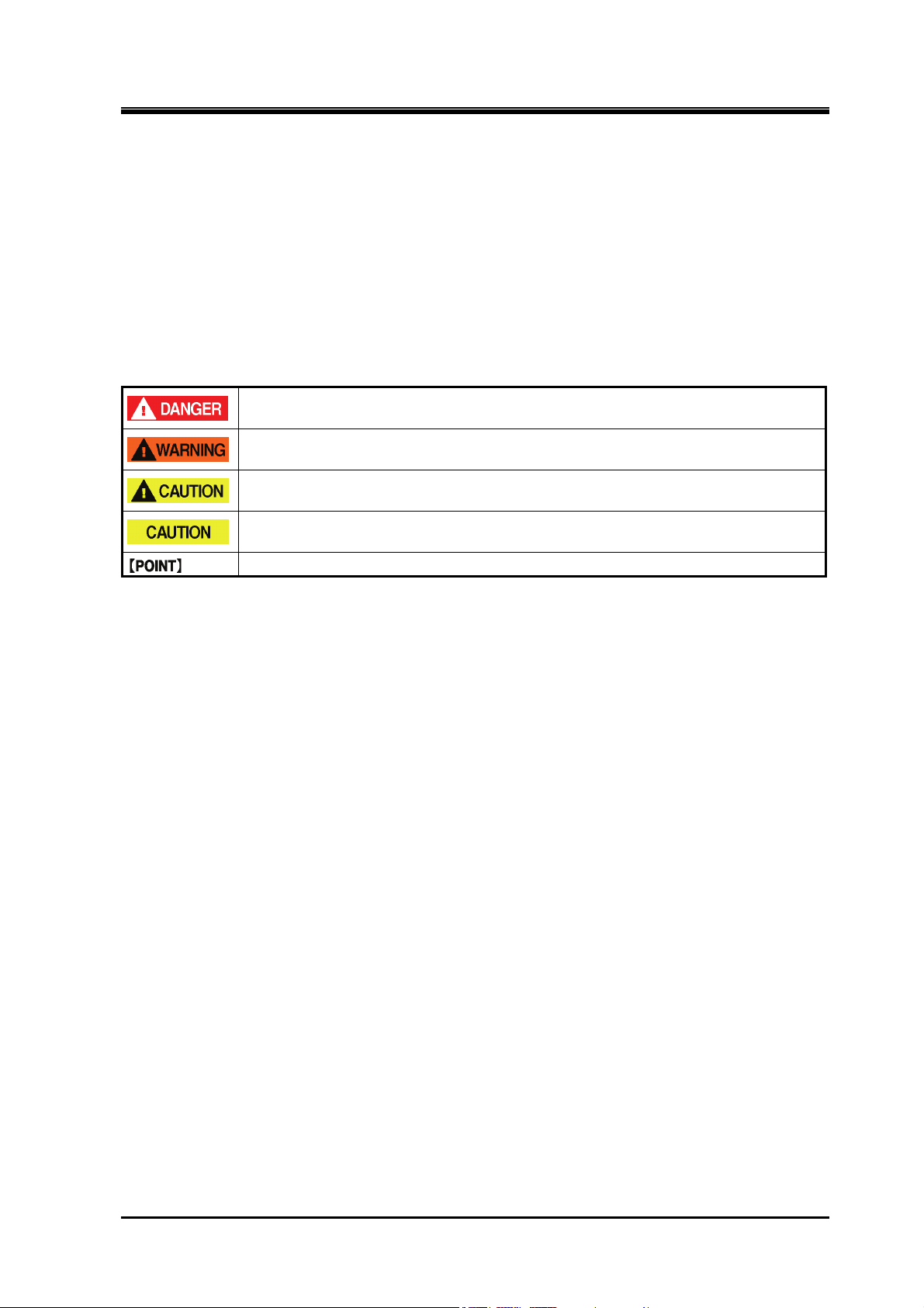
1.2.1 Types and Meanings of Warnings
This manual includes the following four types of warnings to be used for expected hazards during operation
and maintenance of the compressor.
Neglecting such warnings may cause accidents, resulting in personal injury or even death.
Also, the compressor or its auxiliary equipment may be heavily damaged. Therefore, be sure to always
observe the instructions of the warnings.
Indicates an imminently hazardous situation which, if not avoided, will result in serous
injury or death.
Indicates a potential hazardous situation which, if not avoided, could result in serous injury
or death.
Indicates a potential hazardous situation which, if not avoided, may result in minor or
moderate injury.
Indicates a potentially hazardous situation which, if not avoided, may result in property
damage.
Emphasizes important items and indicates profitable information.
1 Safety
Reciprocating Compressor M Series 1.2 Warnings
1-3
2202G1JE-DA-M-N_2010.01.
1 Safety
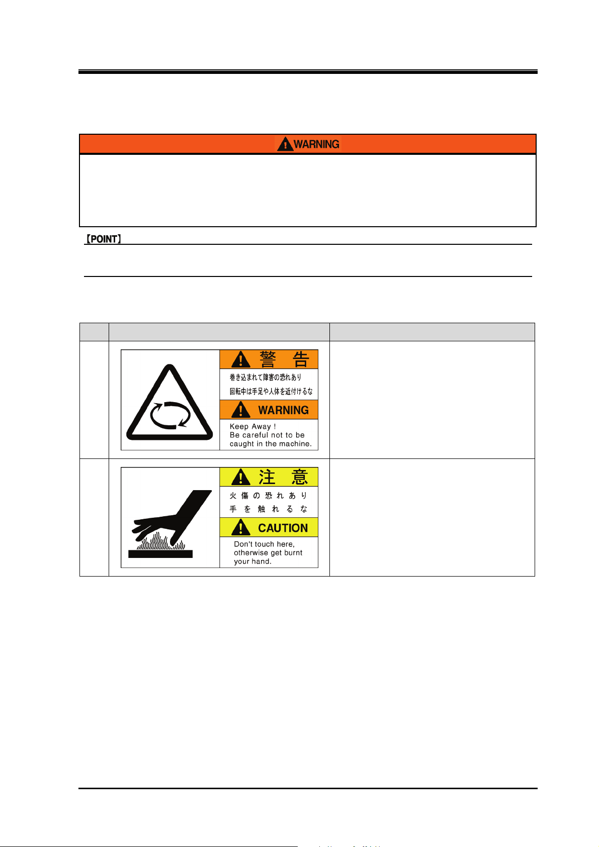
1.2.2 Safety labels
The following shows the types of the safety labels and their positions affixed on the compressor. Always
follow the warnings instructed on the safety label affixed on the compressor.
Be sure to follow the instructions of the safety labels. Otherwise, danger
resulting in personal injury, death, or property damage may arise.
Do not smear, cover, or peel off the safety labels.
If the safety labels are damaged or missing, purchase and affix new labels to their
proper positions according to this manual.
Inform our service center of the product name and safety label No when placing a purchase
order for safety labels.
Types of Safety Labels
Table 1-1 Safety label
No. Safety labels Remarks
1
2
For specification with belt cover
Reciprocating Compressor M Series 1.2 Warnings
1-4
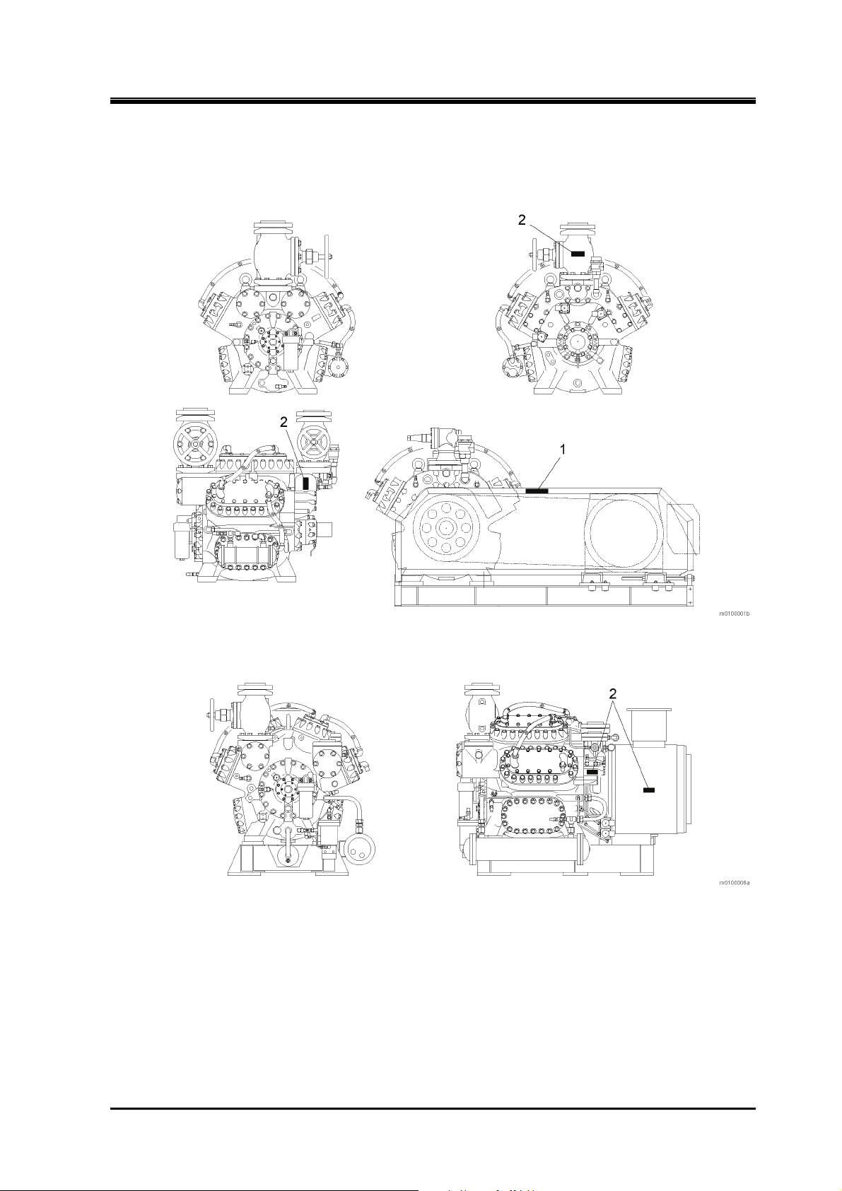
Affixing Positions of Safety Labels
The figure below shows the affixing positions of safety labels.
The numbers in the figure correspond to the ones in Table 1-1 Safety label.
2202G1JE-DA-M-N_2010.01.
1 Safety
Fig. 1-1 Affixing positions of safety labels (Ex: 6M)
Fig. 1-2 Affixing positions of safety labels (Ex:
62M-FM)
Reciprocating Compressor M Series 1.2 Warnings
1-5
2202G1JE-DA-M-N_2010.01.
1 Safety
1.3 Remaining Hazard
The following information is provided on the assumption that this compressor is operated, inspected, and
maintained while being used in general refrigerating, cold storage, and air conditioning systems. Note that all
hazardous sources cannot be predicted for the refrigerating, cold storage, and air conditioning systems you
actually use.
Devise appropriate countermeasures for hazardous sources in your systems.
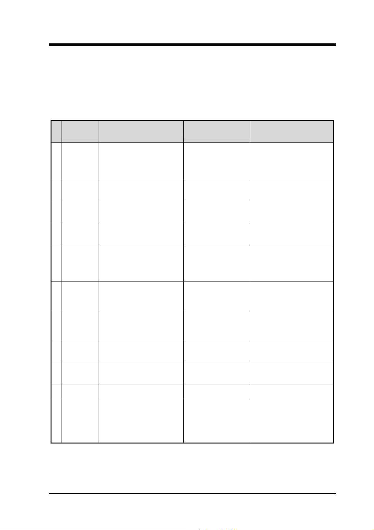
Table 1-2 Hazardous sources
Hazardous
parts
A Driving
section
B Head cover Damage caused by
C Discharge
piping
D Unloader
solenoid
valve
E Heater Electric Shock
F Suction
(side)
shut-off
valve
G Discharge
(side)
shut-off
valve
H Gas purge
valve
I Oil drain Burns
J Noise and
vibration
K Motor Damage caused by high
Predicted hazard
Contact and entanglement in
rotational part
Drop-off of moving part
Recovery after interruption
of energy supply
contacting hot part
Damage caused by
contacting hot part
Electric Shock Installation of guard
Burns
Contact with and inhale of
toxic substances
Low temperature burns
Contact with and inhale of
toxic substances
Burns
Contact with and inhale of
toxic substances
Contact with toxic
substances
Damage caused by noise Wearing protective
temperature
Electric Shock
Counter measures in
operation
Installation of guard
and cover
Installation of guard
Wearing protective
devices
Installation of guard
Wearing protective
devices
Wearing protective
devices
Installation of guard
and cover
Wearing protective
devices
Wearing protective
devices
Sufficient ventilation
Installation of guard
Wearing protective
devices
Sufficient ventilation
Installation of guard
Wearing protective
devices
Sufficient ventilation
Do not contact with it
during operation
devices
Wearing protective
devices
Counter measures in
cleaning, inspection, and
parts exchange
Lockout/tagout of motor
main power and control
power
Wearing protective devices
Operation with a
temperature of 40°C or less
Wearing protective devices
Operation with a
temperature of 40°C or less
Lockout/tagout of control
power
Lockout/tagout of the heater
power
Wearing protective devices
Operation with a
temperature of 40°C or less
Wearing protective devices
Sufficient ventilation
Wearing protective devices
Sufficient ventilation
Operation with a
temperature of 40°C or less
Wearing protective devices
Sufficient ventilation
Wearing protective devices
Operation with a
temperature of 40°C or less
—
Lockout/tagout of motor
main power and control
power
Wearing protective devices
Operation with a
temperature of 40°C or less
Reciprocating Compressor M Series 1.3 Remaining Hazard
1-6
2202G1JE-DA-M-N_2010.01.
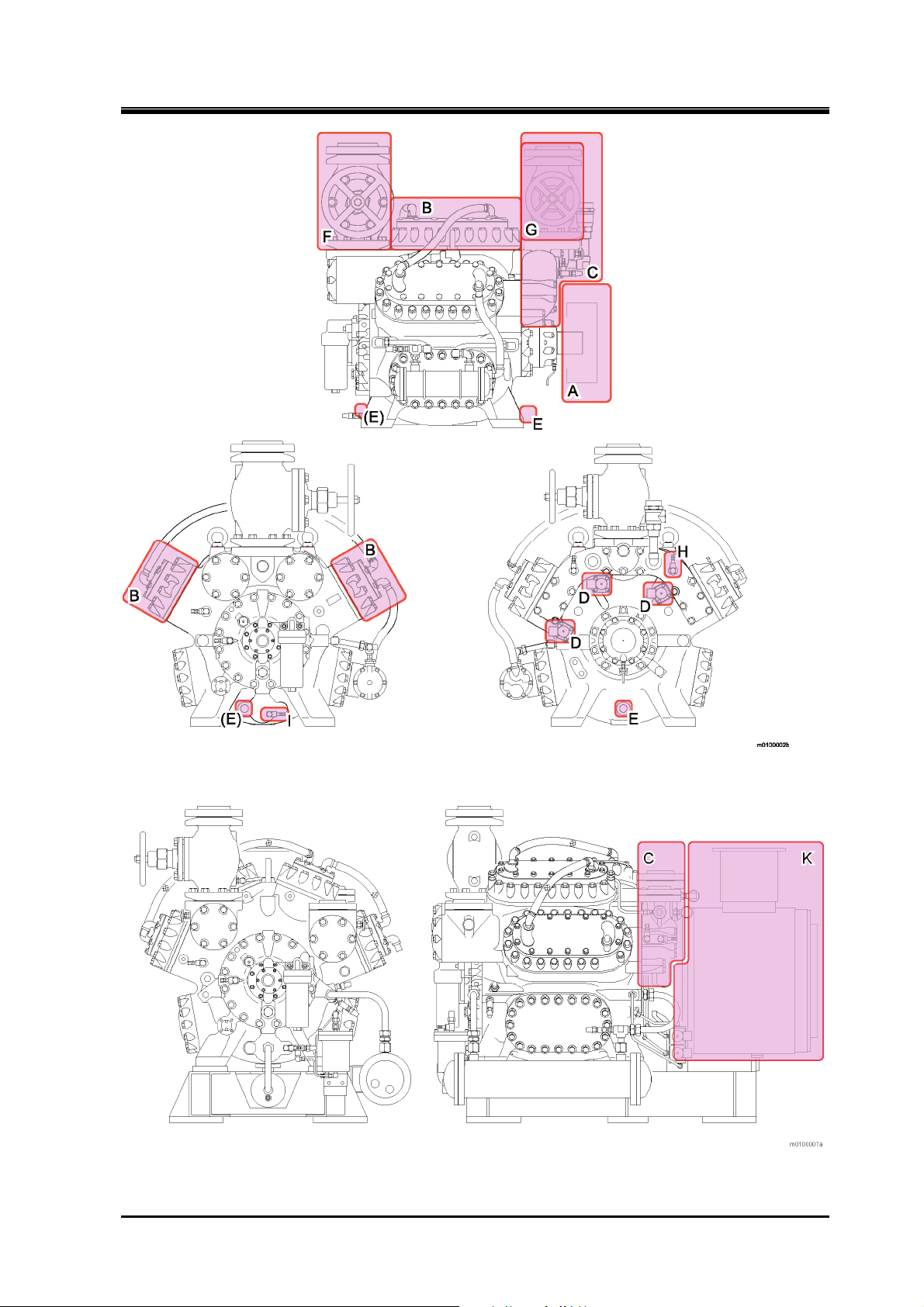
1 Safety
Fig. 1-3 Hazardous sources (Ex: 6M)
Fig. 1-4 Hazardous sources (Ex: 62M-FM)
Reciprocating Compressor M Series 1.3 Remaining Hazard
1-7
2202G1JE-DA-M-N_2010.01.
1 Safety
1.4 Safety Devices
For safe use and protection of the compressor, make sure to attach safety devices to your compressor,
complying with the regulations and the following instructions for each devices.
Periodically perform inspection and maintenance of devices for normal/proper operation. Maintenance and
inspection must be performed as an important part for the safety of machine and personnel. Provide users of
the compressor with necessary information on the safety devices, for example, types of the safety devices,
installation position, function, and inspection method of safety related devices.
Check the safety devices after turning on the power and before operation of the
compressor. If they do not operate normally, immediately take repair or replace
safeties before starting compressor.
1.4.1 Emergency Stop Button
Overview/Function/Purpose
Used to stop the compressor immediately if an emergency occurs in the compressor.
Installation Positions
On the control board on the compressor and in the operation control room
Stop/Restoration Methods
Specify the stop/restoration methods of emergency stop button, and make sure to provide users of this
compressor with them.
Inspection Method/Cycle
The emergency stop button requires test to ensure compressor is shut down when pressed, insure this is done
before testing the operation of compressor and periodically after compressor is put into service. Specify the
inspection methods/cycle of the emergency stop button, and make sure to provide users of this compressor
with them.
1.4.2 Breakers of Motor Main Power and Control Power (with Lockout/Tagout Devices)
Overview/Function/Purpose
When working on compressor (especially during cleaning, maintenance, inspection, and troubleshooting),
ensure to lockout/tagout main and control power to prevent mis-operation and hazards to workers while the
motor main power and control power are turned "OFF".
Methods of Performing and Releasing Lockout/Tagout
Make sure to clearly notify methods of performing and releasing lockout/tagout referring to the regulations
created by Occupational Safety & Health Administration (OSHA) or local governing body.
Reciprocating Compressor M Series 1.4 Safety Devices
1-8
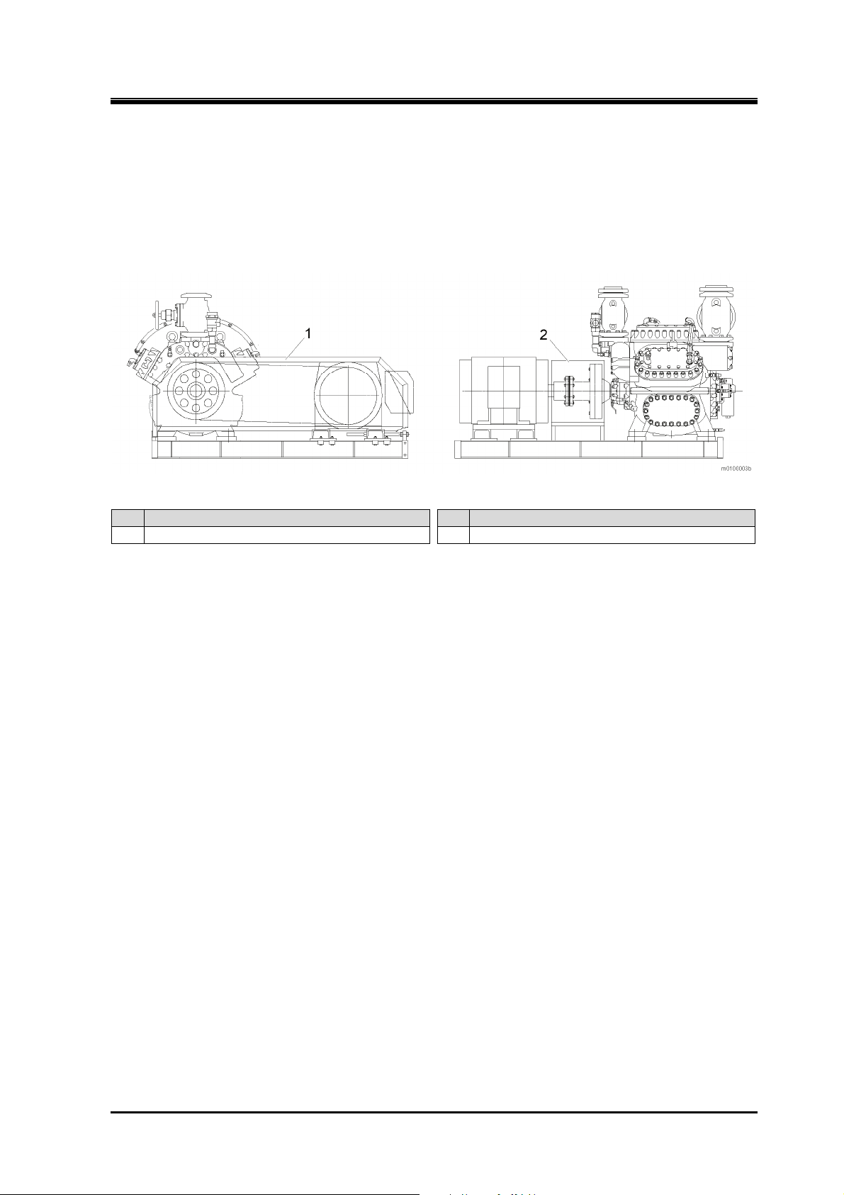
1.4.3 Safety Belt/coupling Guard
Overview/Function/Purpose
Prevents contact and entanglement in the driving section of this compressor.
Installation Positions
Driving section
Fig. 1-5 Attachment of driving section safety cover (6M)
2202G1JE-DA-M-N_2010.01.
1 Safety
No. Description No. Description
Driving section safety cover (for belt) 2 Driving section safety cover (for coupling)
1
Inspection Method/Cycle
Specify the inspection methods/cycle of the safety cover, and make sure to provide users of this compressor
with them.
Reciprocating Compressor M Series 1.4 Safety Devices
1-9
2202G1JE-DA-M-N_2010.01.
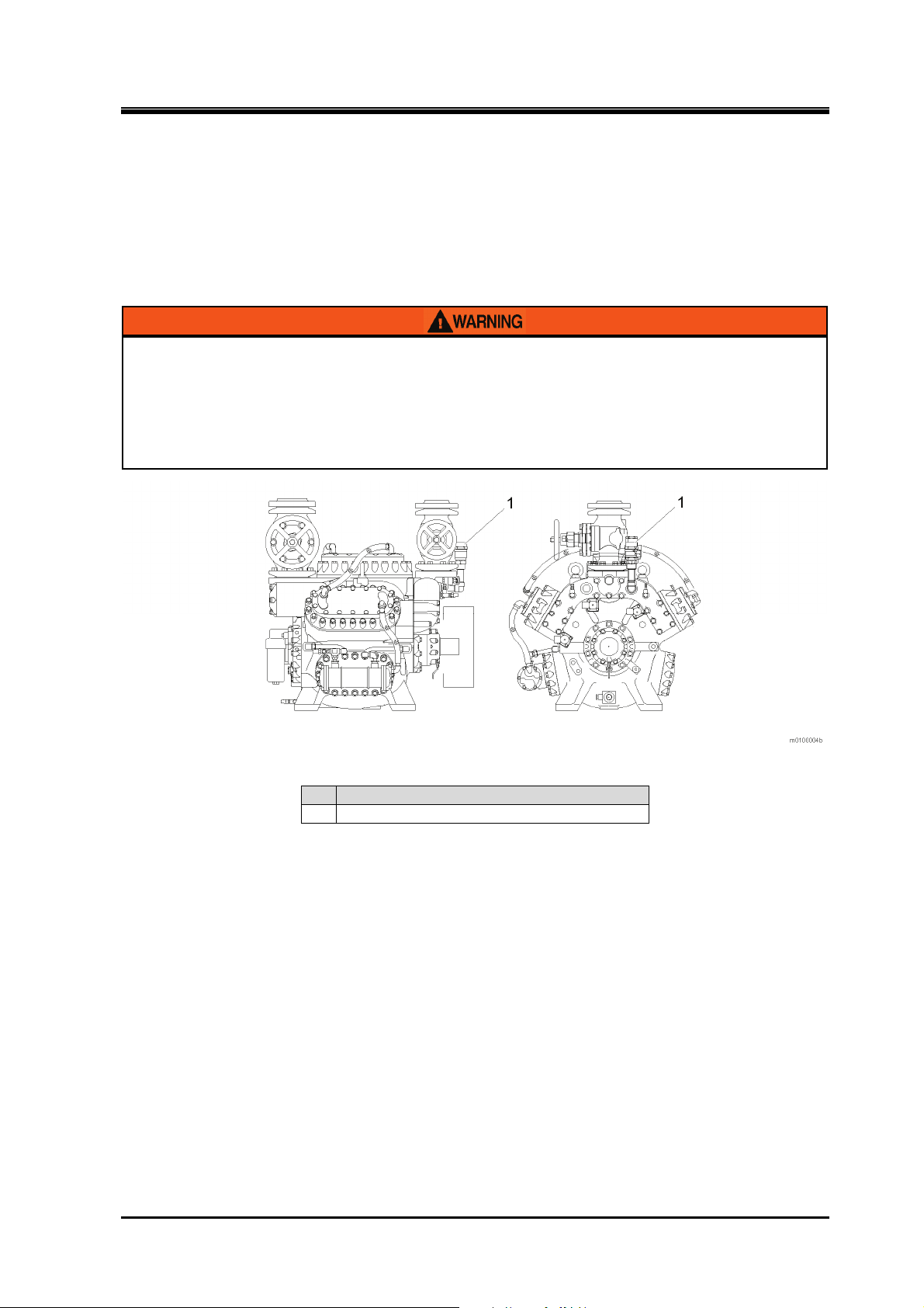
1.4.4 Safety valve
Overview/Function/Purpose
A safety valve is used to prevent the compressor from bursting when its internal pressure rises abnormally.
Installation Positions
Install a safety valve on discharge outlet between the shut-off valve (service valve) and the compressor. Set
the safety valve so that it operates even when the shut-off valve is closed during operation.
Properly terminate the discharge outlet of safety valve according to the type of
refrigerant, following the local, state, federal acts and regulations. If ammonia is
discharged into the atmosphere, it highly possibly causes health damage such as
intoxication and bad smell. And if it is discharged into enclosed space such as
inside of the compressor, it may cause serious accident such as deficiency of
oxygen.
1 Safety
Fig. 1-6 Attachment example of safety valve
No. Description
Safety valve
1
Settings
Set the pressure of safety valve to the designed system pressure or lower. Specify the safety valve settings,
and make sure to provide users of this compressor with them.
Inspection Method/Cycle
Insure to replace or repair safety relief valve following the local, state, federal acts and regulations.
Reciprocating Compressor M Series 1.4 Safety Devices
1-10

2202G1JE-DA-M-N_2010.01.
1 Safety
1.4.5 Automatic Control and Protection Equipment M compressor
Overview/Function/Purpose
Low oil pressure failure protection equipment (OP)
When the oil pressure in compressor (Gauge pressure minus crank case pressure) drops from
deficiency of refrigerant oil, clogging of filter, and interfusion of refrigerant, automatically shuts off
the motor circuit and stops the operation of compressor.
This intended to prevent damage to the compressor from abnormal friction. Can also cause the
unloader mechanism from malfunctioning
High pressure protection equipment (HP)
When the discharge pressure on compressor becomes abnormally high because the compressor is
operated incorrectly or the water supply for condenser is cut. HP switch shuts off the motor circuit
automatically to stop the operation of compressor.
Prevents system ruptures and refrigerant leaks.
Control of the compressor capacity: Low pressure control equipment (LP)
The number of capacity control step in the compressor is determined by the number of cylinder.
Generally two cylinders are considered as one bank. Therefore, capacity control of four steps is
available for eight cylinders, three steps for six cylinders, and two steps for four cylinders. Capacity
control is performed by detecting suction pressure the low pressure control switch is used.
It automatically controls opening/closing of the solenoid valve connected to the unloader piston in the
capacity control mechanism of compressor.
Reciprocating Compressor M Series 1.4 Safety Devices
1-11
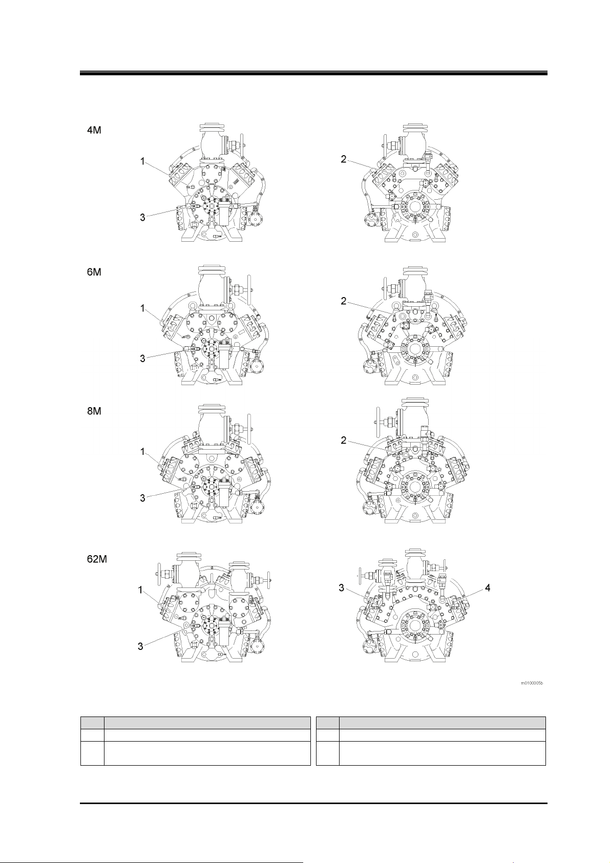
Connecting Positions
2202G1JE-DA-M-N_2010.01.
1 Safety
Fig. 1-7 Connections of low oil pressure failure protection equipment (OP)/
high pressure protection equipment (HP)/low pressure control equipment (LP)
No. Description No. Description
Low pressure gauge connection φ 6 (LP/OP) 3 Oil pressure gauge connection φ 6 (OP)
1
High pressure gauge connection φ6 (HP) 4 Intermediate pressure gauge connection φ 6
2
(OP)
Reciprocating Compressor M Series 1.4 Safety Devices
1-12
 Loading...