

MAYEKAWA 160 GR Instruction Manual

160GR Natural Gas Booster Instruction Manual
Mayekawa all rights reserved. Subject to change without notice. Lat revised in October 2007 p.1
160 GR
Natural Gas Booster
Disassembly and Re-Assembly Instruction Manual
This manual is to provide instructions how to disassemble and re-assemble the 160GR machine.

160GR Natural Gas Booster Instruction Manual
Mayekawa all rights reserved. Subject to change without notice. Lat revised in October 2007 p.2
Contents
1. Introduction .......................................................................................................................................... 4
2. Capacity Control Procedures ............................................................................................................... 4
3. Variable Vi Structure ............................................................................................................................ 4
3.1.1 When the position of the current port is known ...................................................................... 5
3.1.2 When the Current Port is not known .................................................................................... 10
4. Parts Expanded View ........................................................................................................................ 13
4-1 160GR Standard ................................................................................................................. 13
4-2 160GR with Integral Pump .................................................................................................. 14
4-3 Parts Structure Diagram ...................................................................................................... 15
5. Parts List............................................................................................................................................ 17
6. Outer Dimension ................................................................................................................................ 19
7. Disassembly ...................................................................................................................................... 20
Removing the Compressor .............................................................................................................. 20
7.1 Interior Gas Recovery .................................................................................................... 20
7.2 Removing the connecting parts ...................................................................................... 20
7.3 Suspending and Transferring the Compressor ............................................................... 20
7.4.1 Mechanical Shaft Seal .................................................................................................... 22
7.4.2 Unloader Cover .............................................................................................................. 24
7.4.3 Unloader Thrust Bearing ................................................................................................ 25
7.4.4 Balance Piston Cover ..................................................................................................... 27
7.4.5 Unloader Spring Retainer ............................................................................................... 27
7.4.6 Balance Piston, Balance Piston Sleeve .......................................................................... 28
7.4.7 Speed up Gear Casing Cover
........................................................................................ 29
7.4.8 Speed up gear casing .................................................................................................... 30
7.4.9 Disassembly of speed up gear parts on the driving side ................................................ 31
7.4.10 Spindle Roller Bearing .................................................................................................... 33
7.4.11 Disassembly of the speed up gear on the driven side .................................................... 33
7.4.12 Thrust Bearing ................................................................................................................ 34
7.4.12 Suction Cover ................................................................................................................. 36
7.4.13 Rotor, Rotor Casing, Variable Vi Slide Valve .................................................................. 37
7.4.14 Bearing Head and Main Bearing .................................................................................... 39
8. Re-assembly ...................................................................................................................................... 40
8.1 Bearing Head and Main Bearing ......................................................................................... 40
8.2 Rotor Casing, Unloader Slide Valve, Variable Vi Slide Valve, Bearing Head ....................... 40
8.3 Rotor Casing, Rotor ............................................................................................................ 41
8.4 Suction Cover ...................................................................................................................... 41
8.5 Thrust Bearings ................................................................................................................... 41
8.5 Installation of the driven side speed up gear ....................................................................... 42
8.6 Spindle Roller Bearings ....................................................................................................... 43
8.7 Building the Driving Side speed up Gear ............................................................................ 43
8.8 Installation of speed up Gear Casing .................................................................................. 43

160GR Natural Gas Booster Instruction Manual
Mayekawa all rights reserved. Subject to change without notice. Lat revised in October 2007 p.3
8.9 Installation of speed up Spindle .......................................................................................... 43
8.10 Speed up Gear Casing Cover ............................................................................................. 44
8.11 Balance Piston Cover .......................................................................................................... 44
8.12 Unloader Cover ................................................................................................................... 44
8.13 Mechanical Shaft Seal ........................................................................................................ 45
9. Procedures to Adjust End Clearance ................................................................................................. 45
160GR Natural Gas Booster Instruction Manual
Mayekawa all rights reserved. Subject to change without notice. Lat revised in October 2007 p.4
1. Introduction
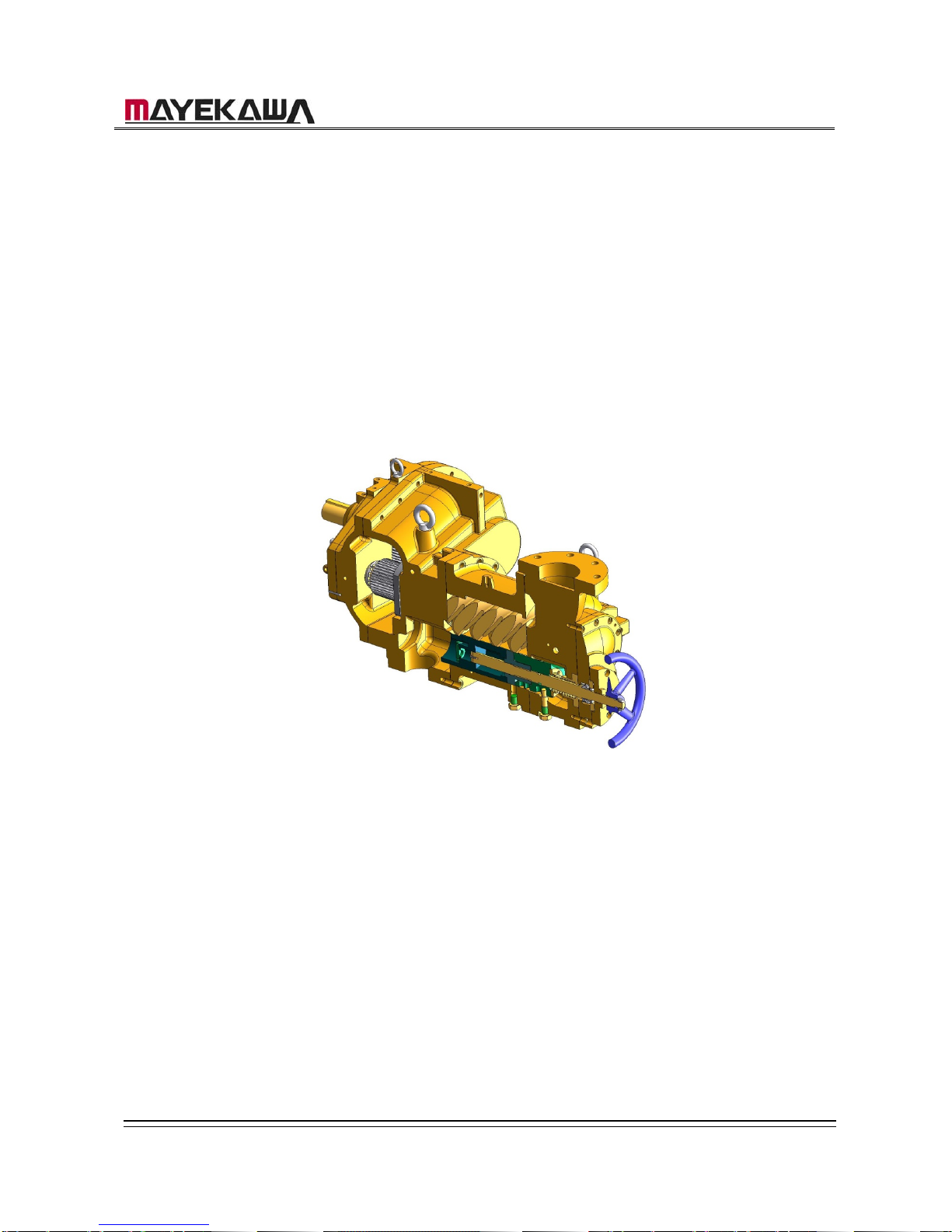
The 160GR is a compressor engineered for the natural gas booster. Provided that it will be
operated by an engine, the compressor itself has an internal speed up gear that allows
different ratios according to the required air volume.
Also, the Vi on the outlet port can be changed in 4 steps with the manual capacity control as
the standard.
2. Capacity Control Procedures
On the standard 160GR specification, the capacity control is done manually by a handle.
Turning the handle in clockwise is for loading, and turning it in counter-clockwise is for
unloading.
The slide valve for the capacity control is fully loading when it is in contact with the surface of
the variable Vi slide valve. The position of Unload is determined by the stopper equipped on
the surface of the under slide rod.
Therefore, the position of full-load of the slide valve depends on the selected Vi; therefore,
the strokes of the slide valve vary as well. The strokes of the slide valve for each Vi setting
are described below.
[CAUTIONS]
・ Although there are stopper structures on the full-load position and the minimum load
position, do not turn the handle with unnecessary force when attempting capacity control.
・ When loading, turning the handle with a relatively little force can easily move the slide valve.
When the slide valve is in contact with t
・ the variable Vi slide valve for full-load, the handle becomes heavy. Then, forcing the handle
to turn may lead to the internal damage.
・
Garph2.1 Strokes for Slide Valve for Each Vi
Vi Setting
The number of rotation
Unload ⇒ Full-Load
2.3 29‐1/2
2.63 26
3.65 21
5.0 17-1/3
3. Variable Vi Structure
To change the Vi on the outlet port, the size of the radial outlet port needs to be changed by
moving the variable Vi supplementary slide valve on the full-load.
The variable Vi supplementary slide valve is fixed to the case by fix pins through pin holes on
the Variable Vi slide valve. The pin holes are located to accommodate the 4 different Vi
settings so that the Vi can be changed step-by-step.
On 160GR, the fix pins of the Variable Vi slide valve are attached from the outside of the case.
When the pins are removed, the interior gas will be discharged to the air. When changing Vi
160GR Natural Gas Booster Instruction Manual
Mayekawa all rights reserved. Subject to change without notice. Lat revised in October 2007 p.5
settings, make sure that the compressor is at a stop and that the gas inside the compressor is
discharged in the air.
Vi should not be changed while the compressor is running.
To Change Vi Settings
[CAUTIONS]
・ On this compressor, Vi should be changed after the compressor is opened to the
atmosphere.
・ Vi settings should be changed while the compressor is stopped. Also, make sure the drive is
not moving or will not move.
・ The interior air pressure of the compressor needs to be equal to the air pressure before
proceeding with changing Vi settings.
Figure1: Variable Vi Structure Cut-up View
The compressor is set at the M port when shipped. Choose the most appropriate Vi setting
for the expected operating conditions.
When the appropriate port is to be other than the M port, the Vi setting needs to be changed
before operations. When the pressure conditions dramatically change during an operation,
the Vi needs to be changed to an appropriate setting.
There are 4 ports: H (Vi=5.0), M (Vi=3.65), L (Vi=2.63), K (Vi=2.3).
3.1.1 When the position of the current port is known
When the position of the current port is known, change the Vi setting by referring to
[Graph1] and choosing the appropriate number of rotations and the direction of the rotation.
a) Make sure the slide valve is on full-load on the current Vi condition (Turn the capacity
control handle in clockwise until it stops).
160GR Natural Gas Booster Instruction Manual
Mayekawa all rights reserved. Subject to change without notice. Lat revised in October 2007 p.6
b) Remove the guide pin from the case. When the current port is “K” or “L,” the guide pin is
located in the bottom area of the suction cover. When the current port is “M” or “K”, they
are located on the bottom of the rotor casing.
c) Turn the handle as many times as required to change to the desired Vi. When changing
to a higher Vi, turn the handle to the left. When changing to a lower Vi, turn the handle to
the left. For the number of rotations, refer to the Graph 2.1. Variable Vi valve can be
moved by turning the handle softly.
d) When changing the ports from the “K / L “ ports to the “M / H” ports, or vice versa, the plug
needs to be removed from the case and replaced with the Variable Vi valve fixing bolts.
e) On the “K” and “L” ports, the Variable Vi support guide pin should be attached to the
bottom of the suction cover. The plug should be attached to the bottom of the rotor
casing.
On the “M” and “H” ports, contrarily, the Variable Vi support guide pin should be attached
to the bottom of the rotor casing. The plug should be attached to the bottom of the suction
cover.
f) After moving the variable Vi slide valve, put the Vi guide pin into the case and lock them
with the hexagon socket head cap screws. With the Variable Vi support guide pin, use the
dice studs for the seal.
When the Vi guide pin feels heavy or caught by something, it should not be forced into the
holes. When this happens, it’s most likely that the position of the holes of the variable Vi
valve and that of the variable Vi valve fixing pin are not aligned. Slightly turn the handle to
the right or the left to find the position where the pin can be inserted smoothly.
g) When the variable Guide pin is smoothly inserted all the way, lock them by a proper
torque. Pun the dice stud for the seal in, and lock them in a different position from the
Variable Guide pin.
[CAUTION]
Head sizes of the variable Vi fixing bolts and the plug are not the same to avoid mistakes.
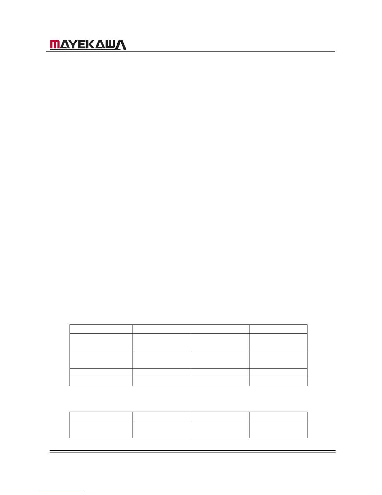
From the K port
K Port ⇒ L Port K Port ⇒ M Port K port ⇒ H Port
Moving Distance
(mm)
21 50.5 72
Number of Rotations
of Handle
3-1/2 8-3/8 12
Direction of Rotations
Counter-clockwise Counter-clockwise Counter-clockwise
Position of fixing pin Suction Cover Rotor Casing Rotor Casing
From the L Port
L Port ⇒ K Port L Port ⇒ M Port L Port ⇒H Port
Moving Distance
(mm)
21 29.5 51
160GR Natural Gas Booster Instruction Manual
Mayekawa all rights reserved. Subject to change without notice. Lat revised in October 2007 p.7
Number of Rotations
of Handle
3-1/2 4‐7/8 8-1/2
Direction of Rotations
Clockwise Counter-clockwise Counter-clockwise
Position of fixing pin Suction Cover Rotor Casing Rotor Casing
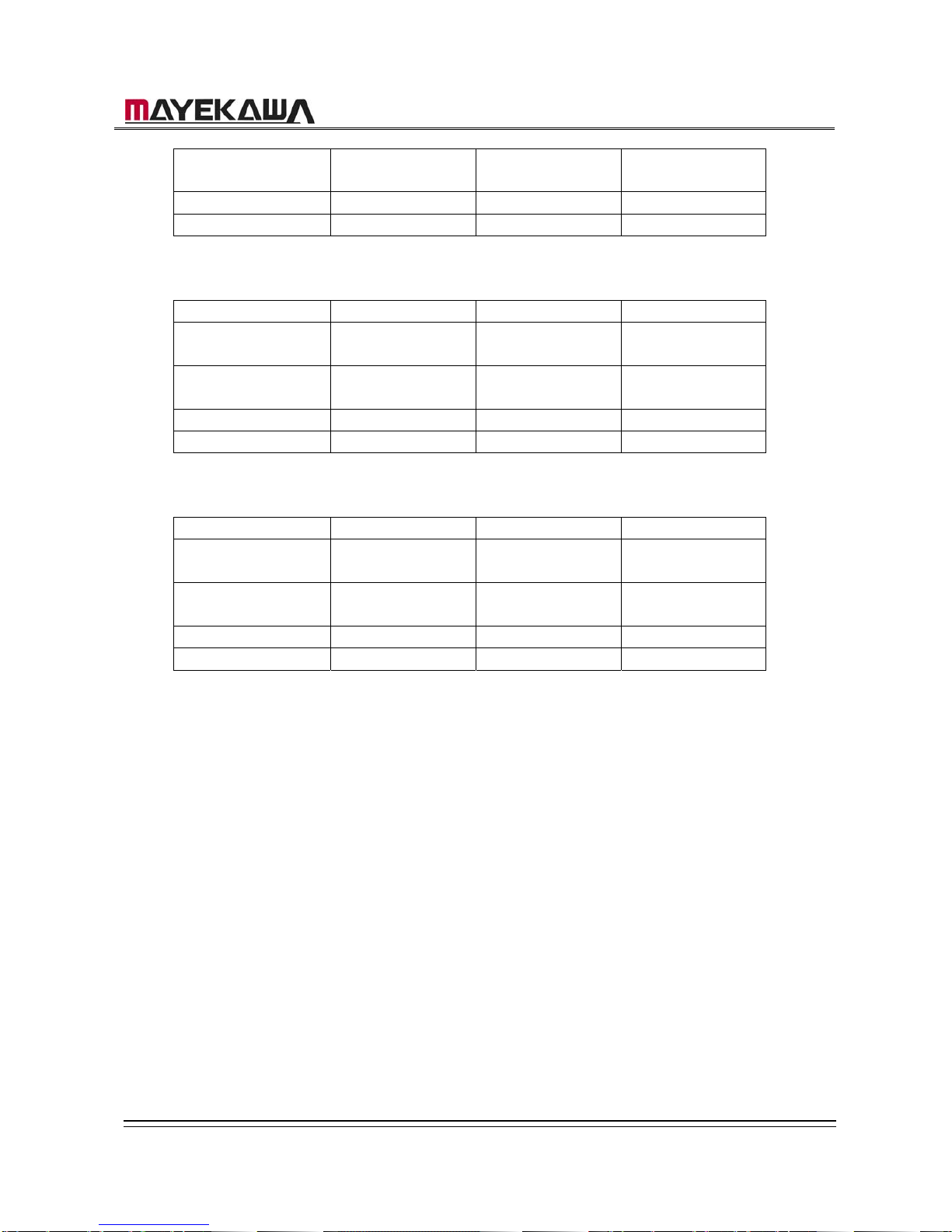
From the M Port
M Port ⇒ K Port M Port ⇒ L Port M Port ⇒ H Port
Moving Distance
(mm)
50.5 29.5 21.5
Number of Rotations
of Handle
8-3/8 4-7/8 3-5/8
Direction of Rotations
Clockwise Clockwise Counter-Clockwise
Position of fixing pin Suction Cover Suction Cover Rotor Casing
From the H Port
H Port ⇒ K Port H Port ⇒L Port H Port ⇒ M Port
Moving Distance
(mm)
72 51 21.5
Number of Rotations
of Handle
12 8-1/2 3-5/8
Direction of Rotations
Clockwise Clockwise Clockwise
Position of fixing pin Suction Cover Suction Cover Rotor Casing
160GR Natural Gas Booster Instruction Manual
Mayekawa all rights reserved. Subject to change without notice. Lat revised in October 2007 p.8
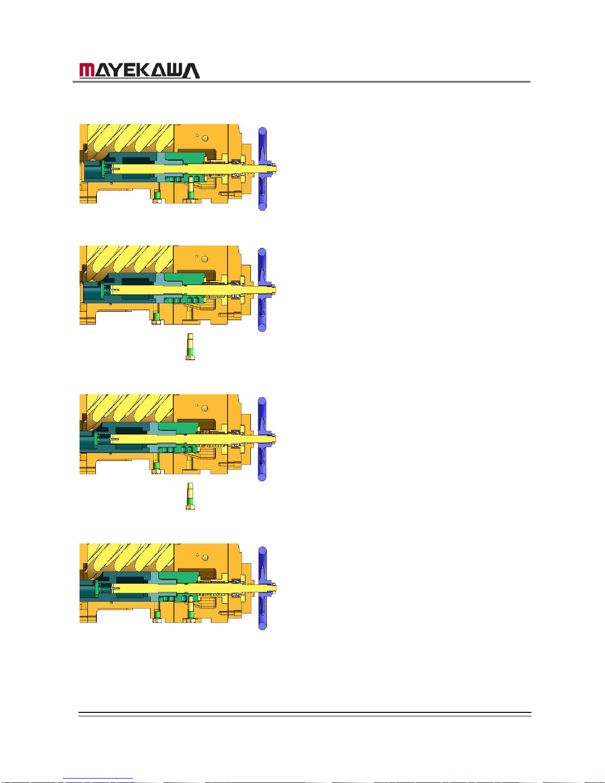
・Vi Changing Procedures < From K-Port to L-Port >
① the Position of K-Port
② Remove the Variable Vi guide pin.
③ Turn the capacity control handle 3 1/2 times
in counter-clockwise, and move the
Variable Vi slide valve to the L-port position.
④ Screw the Variable Vi guide pin in. If it is
tight, turn the handle slightly in both
directions and find a loose spot.
This completes the procedures for
changing to L-Port.
160GR Natural Gas Booster Instruction Manual
Mayekawa all rights reserved. Subject to change without notice. Lat revised in October 2007 p.9
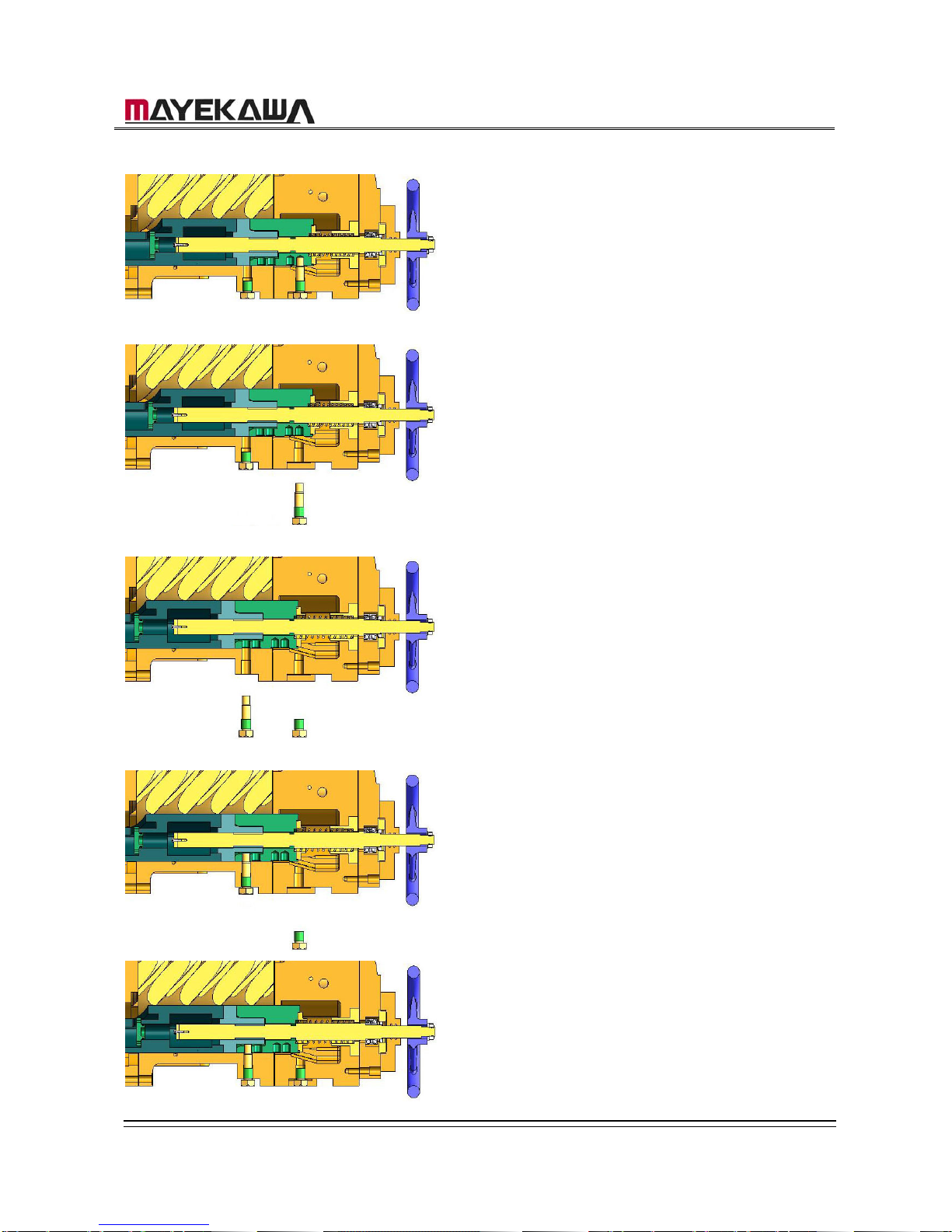
・Vi Changing Procedures < From L-Port to M-Port >
① The position L-Port
② Remove the Variable Vi guide pin from the
bottom of the suction cover.
③ Turn the capacity control handle 4 7/8 times
in counter-clockwise and remove the set
bolt from the bottom of the rotor casing.
Replace it with Variable Vi guide pin.
④ Screw the Variable Vi guide pin into the
bottom of the rotor casing. If it is tight, turn
the capacity control handle slightly in both
directions.
⑤ Lock the set bolt into the bottom of the
suction cover.
This completes the procedures for
changing to the M Port.
160GR Natural Gas Booster Instruction Manual
Mayekawa all rights reserved. Subject to change without notice. Lat revised in October 2007 p.10
3.1.2 When the Current Port is not known
When the position of the current port is not known, move the Variable Vi valve to the
position of the stopper on the loading side. Then turn the handle as many times as
required in order to change to the desired Vi and move the Variable Vi valve.
a) Remove the Variable Vi support guide pin from the case. (The one with the larger
size of the hex head (30mm) is the guide pin.)
b) Turn the handle in clockwise until the Variable Vi valve touches the stopper.
c) According to Graph2.1, turn the capacity handle as many times as required in
counter-clockwise and move the Variable Vi support slide valve.
On the “K” and “L” ports, the Variable Vi support guide pin should be attached to the
bottom of the suction cover, and plug should be attached to the bottom of the rotor
casing.
On the “M” and “H” ports, contrarily, the Variable Vi support guide pin should be attached
to the bottom of the rotor casing, and the plug should be attached to the bottom of
the suction cover.
d) After moving the Variable Vi support slide valve, insert Vi support guide pin and lock
it with the hex bolt. Insert the dice stud for the seal into the Variable Vi support slide
valve before tightening it.
e) When the Vi guide pin feels heavy or caught by something, it should not be forced
into the holes. When this happens, it is most likely that the position of the hole of the
Variable Vi vale and that of the Variable Vi valve guide pin are not proper aligned.
Slightly turn the handle to the right or the left to find the position where the pin can
be inserted smoothly.
f) After the Variable guide pin is smoothly inserted all the way, lock it by a proper
torque. Put the dice stud for the seal in, and lock it at the position opposite to that of
the Variable guide pin.
[CAUTION]
・ If the turning handle feels heavy, do not force the handle to turn. This may result to
damage the stopper area.
・
K Port L Port M Port H Port
Moving Distance
(mm)
5 26 56 77.5
Number of Rotations
of Handle
13/16 4-3/8 9-3/8 12-15/16
Direction of
Rotations
Counter-Clockwise Counter-Clockwise Counter-Clockwise Counter-Clockwise
Position of guide pin
Suction Cover Suction Cover Rotor Casing Rotor Casing

160GR Natural Gas Booster Instruction Manual
Mayekawa all rights reserved. Subject to change without notice. Lat revised in October 2007 p.11
160GR Natural Gas Booster Instruction Manual
Mayekawa all rights reserved. Subject to change without notice. Lat revised in October 2007 p.12
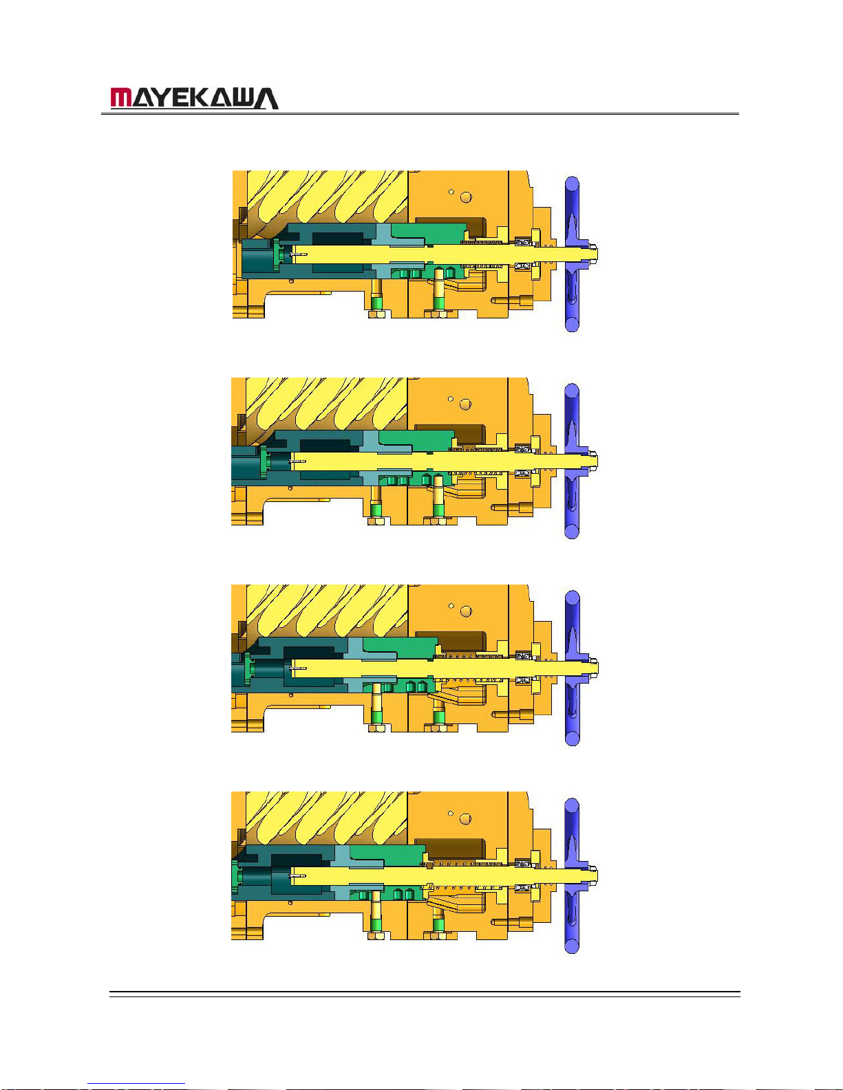
Each Port and the Position of the Variable Vi guide pin
K-Port
L-Port
M-Port
H-Port
160GR Natural Gas Booster Instruction Manual
Mayekawa all rights reserved. Subject to change without notice. Lat revised in October 2007 p.13
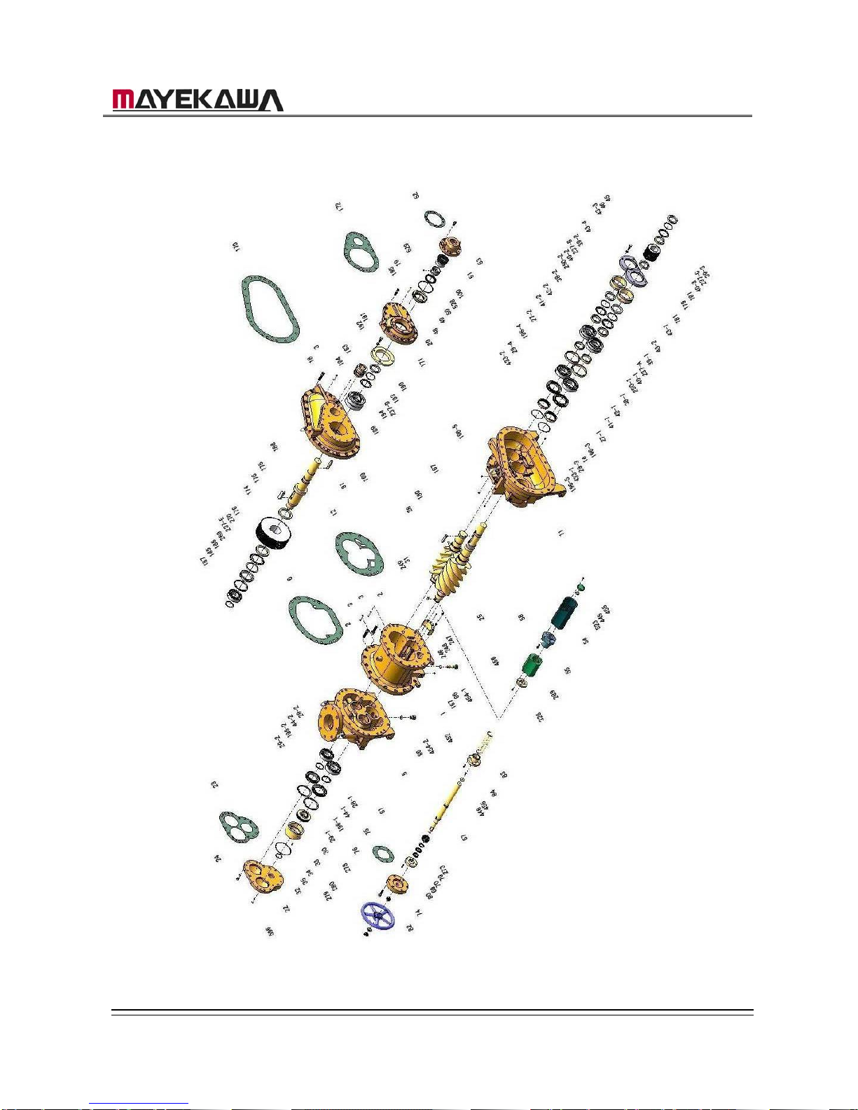
4. Parts Expanded View
4-1 160GR Standard
160GR Natural Gas Booster Instruction Manual
Mayekawa all rights reserved. Subject to change without notice. Lat revised in October 2007 p.14
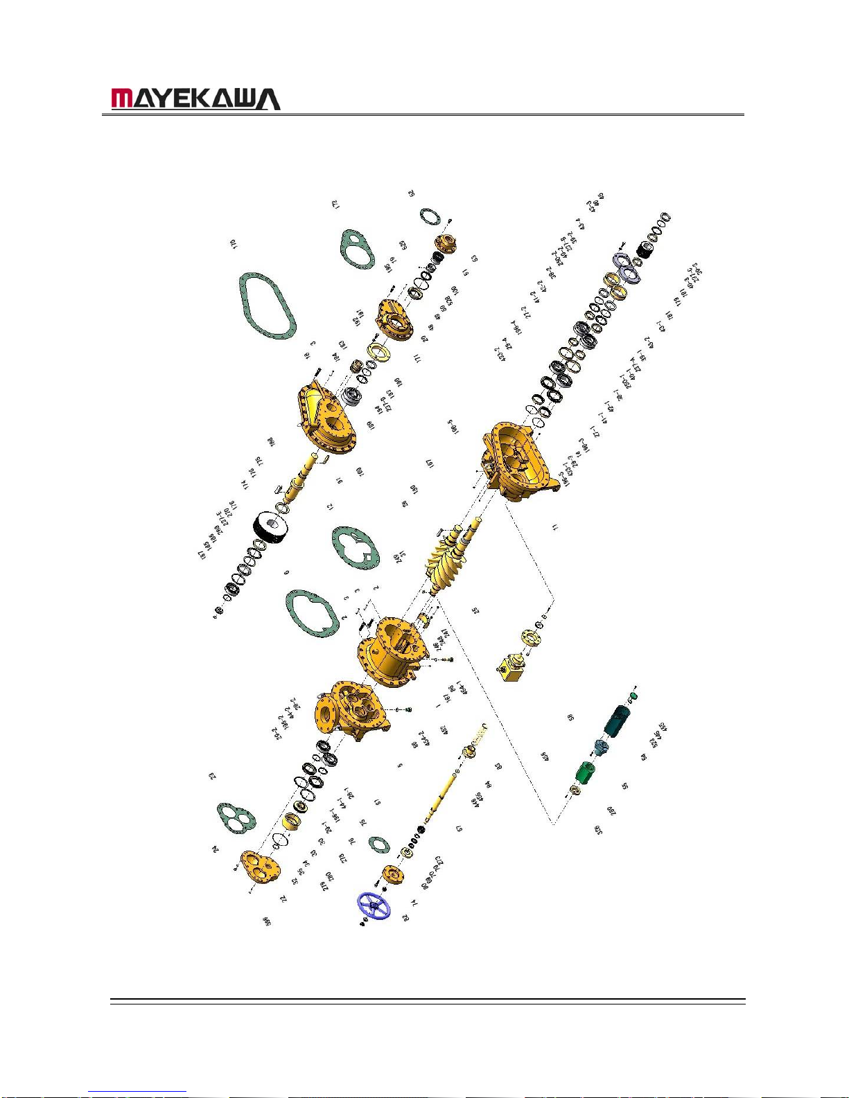
4-2 160GR with Integral Pump
 Loading...