

Maycom EH-465 User Manual
NEMO21 INFORMATION
& COMMUNICATIONS
FCC ID: O7MPRO-301
JOB # 106AK0
EXHIBIT # 9A-9W
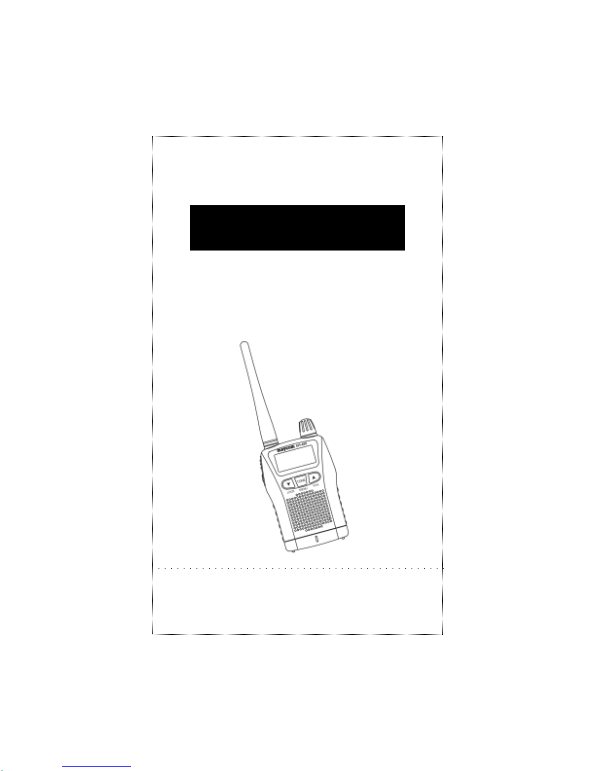
MINI HAND HELD TYPE
UHF TRANSCEIVER
user’s manual
MODEL : EH-465
CONTENT

INTRODUCTION ………………….………………..……………
4
GENERAL FEATURES ………………………………………… 4
DESCRIPTION OF FEATURES ……………………………… 5
1. Top Panel Features ……………………………..…………… 5
2. Side and Back Panel Features ……………………..……..…. 6
3. Bottom side Features …………………………………. ……. 8
4. Display Panel Features …………………..…………………. 9
5. Front Panel Features ………………………………………. 11
FRS CHANNEL FR EQUENCY TABLE ………….……...…. 14
CTCSS ……..……………………………………………..………
14
OPTION SETTING MODE …………………………..……… 15
BATTERY INSTALLATION ISTRUCTIONS ……………… 19
TO REC EIVE ..………………………………………….……… 20
TO TRANSMI T ..……………………………………………… 20
INITIALIZATION ..…………………………………………… 21
RANGE …………………………………………..…………..… 21
EASY AND COMMUNICATIONS ……………..…………… 21
SPECIFICATION ……………………………………………… 22
TROUBLESHOOTING ……………………………………… 23
INTRODUCTION
3

Congratulations on your purchase of the maycom EH-465
Advanced Family Radio Service (FRS) Portable radio. Your
maycom radio is designed to provide trouble-free service and
advanced user features to make it the premier choice in radio
communications.
GENERAL FE ATURES
Compact size and light weight
Easy viewing multi-purpose LCD display
CPU controlled frequency synthesizer for reliable operation
CTCSS Tone Squelch system to avoid interference
Advanced user features – Vox, Scan, Call Tones, Melody Call
and Roger Beep
Operates on 4 AAA alkaline batteries, Ni-Mh Rechargeable
Battery Pack or DC Power Supply
Connections for optional accessories to enhance your
communication pleasure
Belt Clip and hand strap for easy carrying
FCC ID : O7MPRO-301
NEMO21 INF ORMATION & COMMUNICATION S
THIS DEVICE COMPLI ES WITH PART 15 OF THE FCC RUL ES.
OPERA T ION IS SUBJ ECT T I THE FOLLOWING TWO CON DITIONS:
(1) THIS DEVICE MAY NOT CAUSE HARMFUL INTERFERENCE,
AND
(2) THIS DEVICE MUST ACCEPT ANY INTERFERENCE RECEIVED,
INCLUDING INTERFERENCE THAT MAY CAUSE UNDERSIRED
OPERATION.
4
DESCRIP TION OF FEATURES
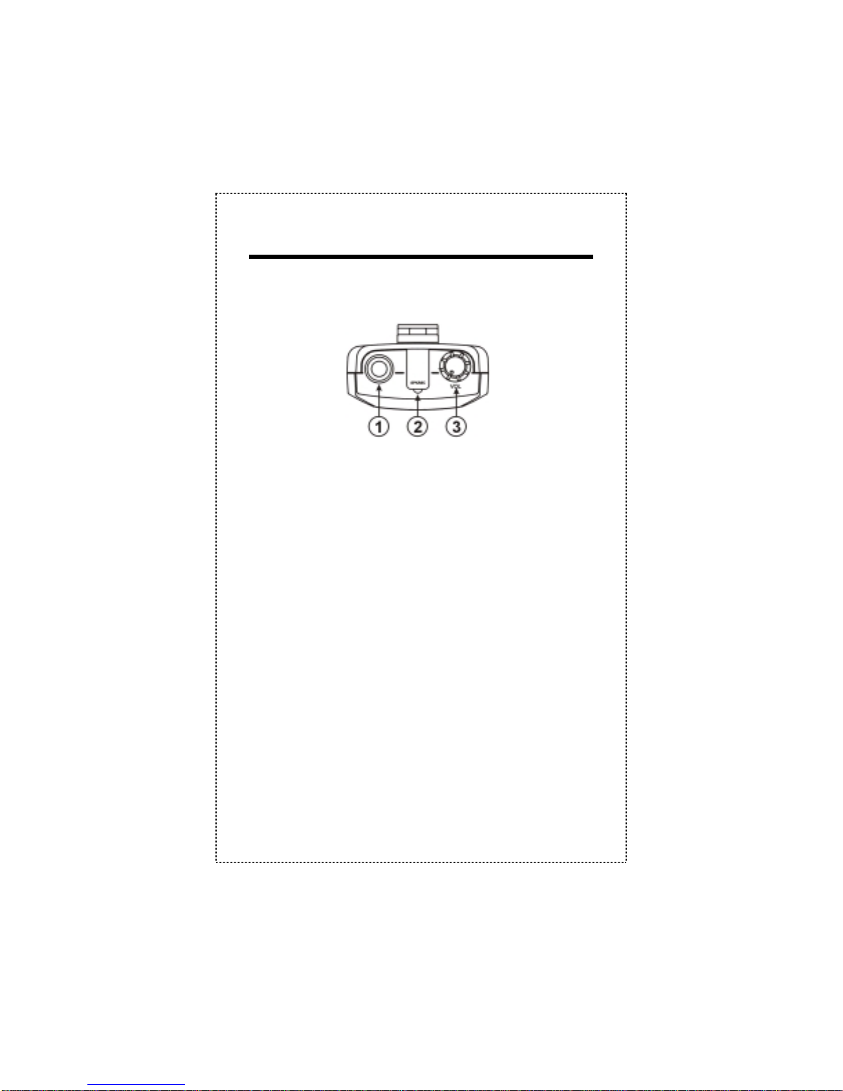
1. Top Panel Features
1) Power On/Off, Volume Control
Turn the volume control clockwise to switch power on and
set volume to desired level. Turn the volume control
counter-clockwise to turn power off.
2) Antenna
The antenna is an integral part of FRS radio for maximum
performance. Do not modify or connect any external device
to antenna to change its characteristics.
3) Microphone and Speaker Jack
Jacks are provided for connection of optional
speaker/microphone maycom accessories.
4
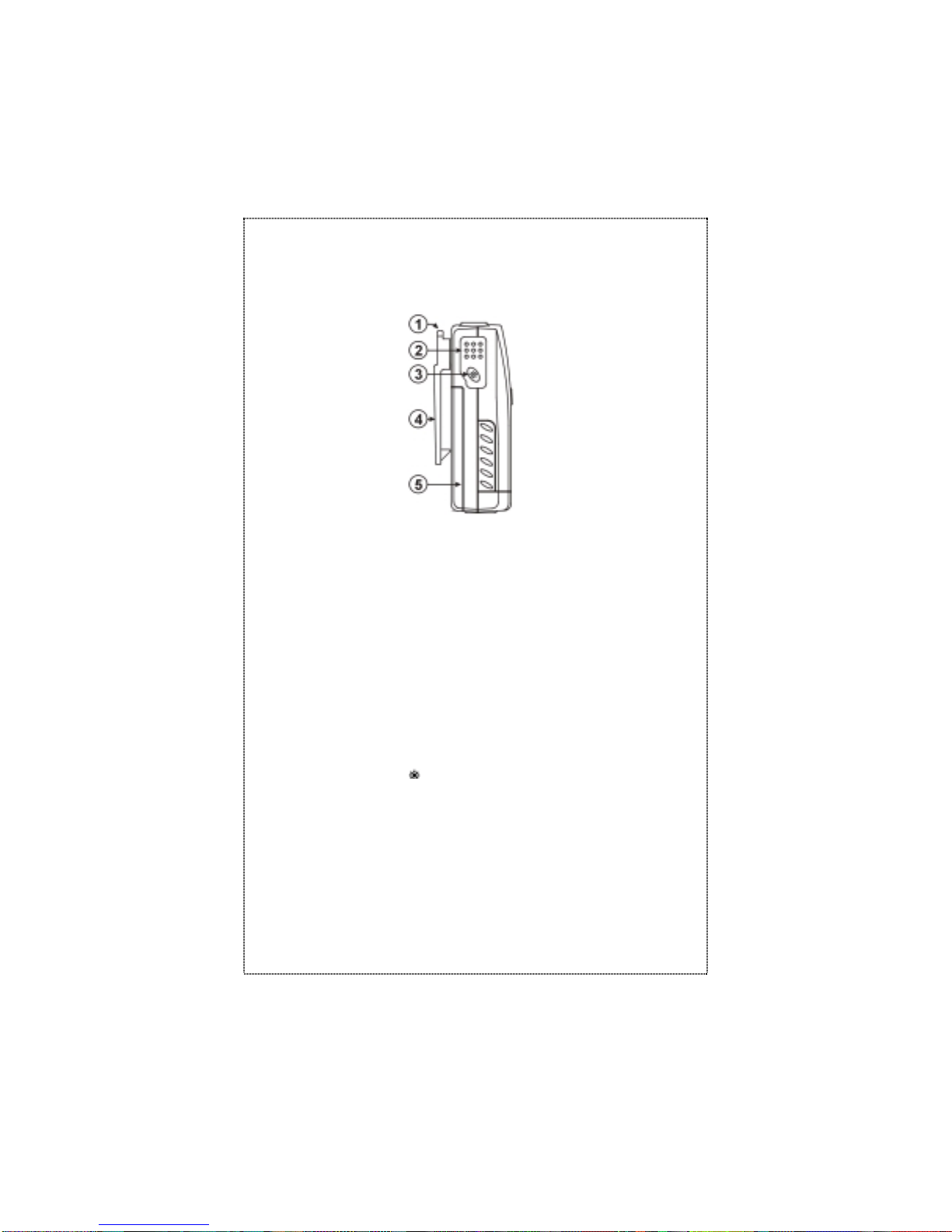
2. Side and Back Panel Features
1) Flexible Wrist Strap
Placing the strap around the wrist will prevent the radio
from
falling to the ground(Strap is in accessory pouch).
2) PTT(Push-To-Talk) Button
Press the “PTT” button to activate the transmitter. Talk in a
normal voice about 2-3 inches from the front panel. When
external microphone is connected, the external PTT control
is activated. To receive, just release “PTT” button.
3) Lamp button
•Press the lamp button. The lamp will stay on during
pressing.
∙Monitor
Press Lamp button for a 2 sec in receiving mode, both
carrier and tone squelch circuit will be temporarily
disabled. Receiver/audio will sound on the loudspeaker
until the “Lamp” button is released.
5

∙
Bell Feature
Function : The user is alerted to incoming calls by bell
indicator and an audible tone from the radio.
To Activate : Turn the power off
α Press the lamp button and then turn the
power on
β The Bell icon “ ” will appear on the LCD.
Upon receiving an incoming call, the alert function will be
activated for about 8 seconds and then stopped for 15
trigger the alert device. The radio will automatically re armed and ready for another alert after the 15 seconds
timer expires.
To De-Activate : Turn the power off and on. The Bell icon
“ ” will disappear from the LCD.
4) Belt Clip
Allows for easy of carrying while attached to user’s belt.
(One screw and clip are in accessory pouch).
5) Battery Case
See “Battery Installation Instruction” for details.
6
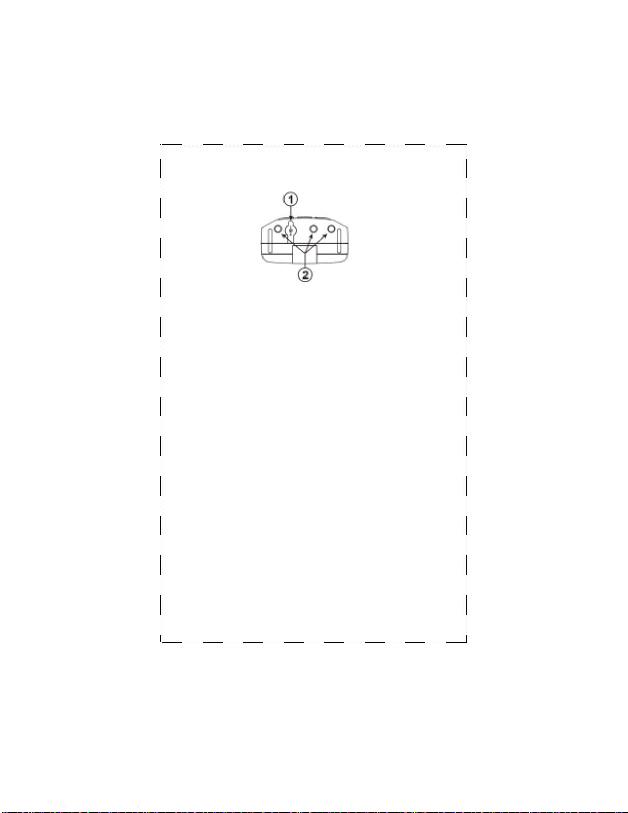
3. Bottom side Features
1) DC Jack
For connection to AC Wall Charger, or optional Car
Cigarette Lighter DC power Supply Adaptor. Do not
connect
charger or power supply to the radio if you are using
Alkaline Batteries.
2) Bottom Charger contact for Desktop Charger
To charge the rechargeable battery pack with desktop
charger , this contact point will be used.
7
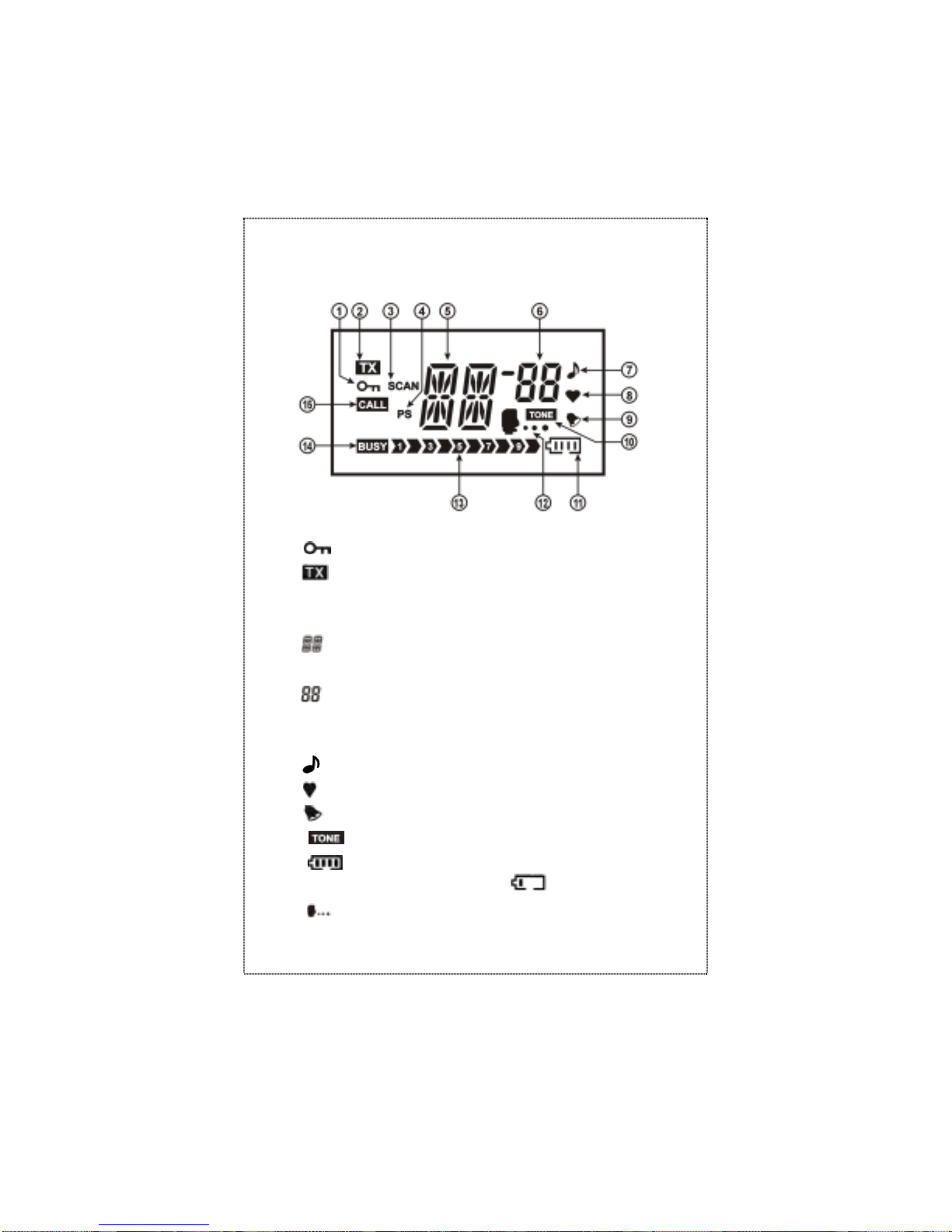
4. Display panel featur es
1) : :
2) :
3) SCAN :
4) PS :
5) :
operating on.
6) :
is
operating on.
7) :
8) :
9) :
10) :
11) :
battery level is two low, “ ” will be flashing.
12) :
Indicates the “Key lock” feature has been activated.
Indicates that radio is the “Transmit” mode.
Indicates the “SCAN” feature has been activated.
Indicates that the radio is in the “Battery save” mode.
Displays the channel number in which the radio is
Displays the CTCSS tone number in which the radio
Indicates that “Beep” tone confirmation is on.
Indicates that “Roger Beep” tone confirmation is on.
Indicates that “Bell” feature has been activated.
Indicates “TONE” is on.
Indicates the amount of battery power left. If the
Indicates the “VOX” feature has been activated.
8
 Loading...