

Page 1
1
Page 2
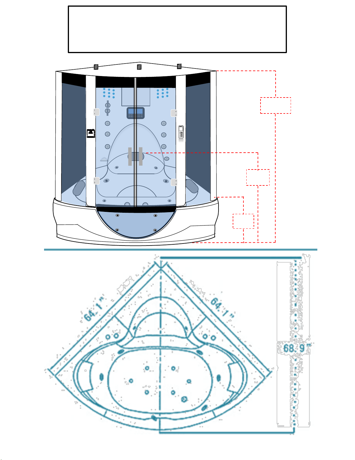
87.8”
30”
24”
STEAM SHOWERS
SPECIFICATION SHEET
Page 3
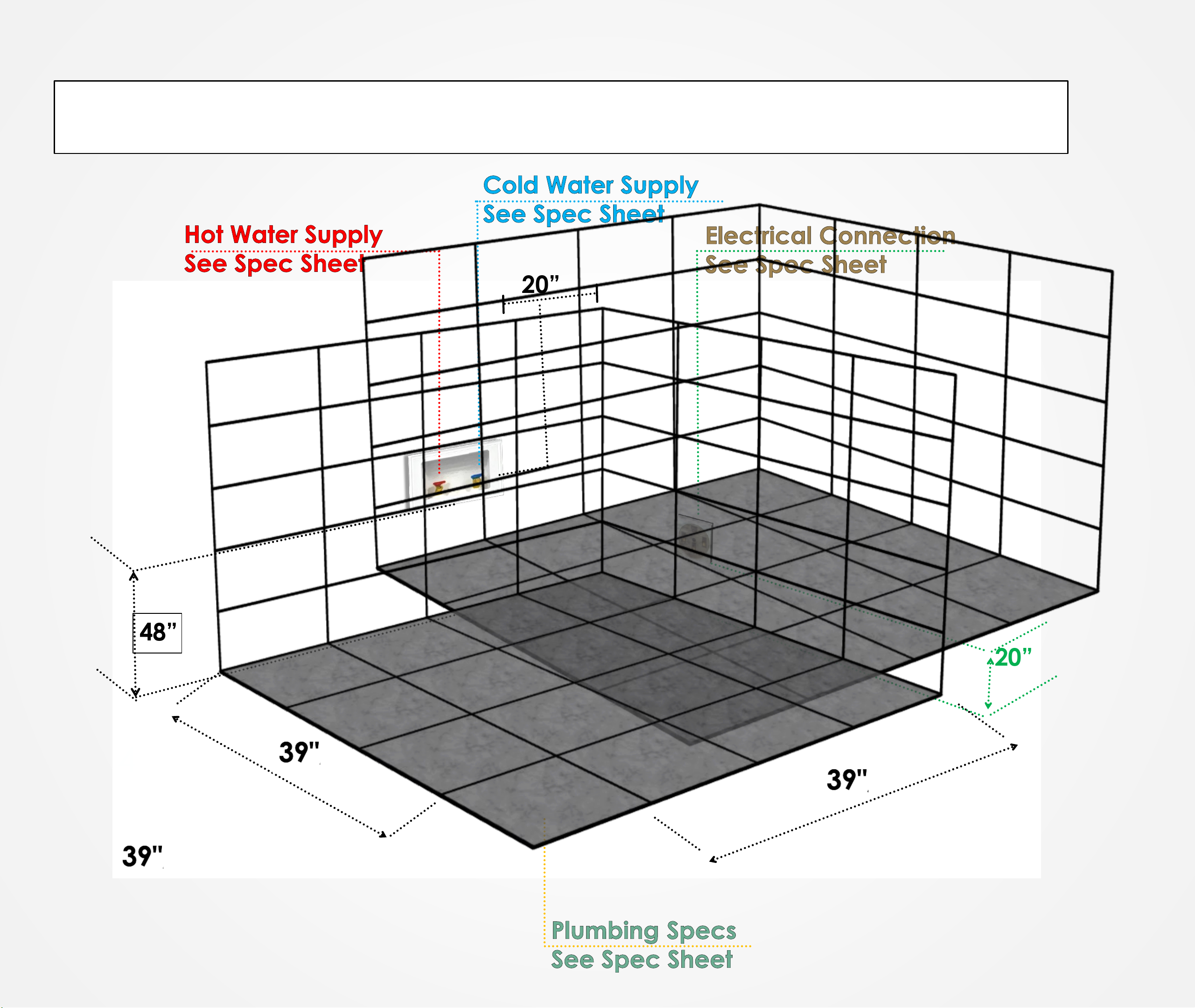
20”
48”
47”
20”
4
Page 4

TABLE OF CONTENTS
ROOM SPECIFICATIONS
ELECTRICAL SPECIFICATIONS
PLUMBING SPECIFICATIONS
TECHNICAL SPECIFICATIONS
INTRODUCTION
ASSEMBLY AND PLANNING
CONNECTING ELECTRIC TO THE HOMES MAIN CIRCUITS
SOME NOTES NOT TO FORGET
POWER REQUIREMENTS
TOOLS NEEDED TO GET THE JOB DONE
CRATE CONTENTS
CRATE# 1 (the large one)
CRATE# 2 (the smaller one)
WATER PRESSURE REQUIREMENT
WATER GALLONS PER MINUTE (GPM) REQUIREMENT
PACKING LIST
BEGIN INSTALLATION
STEP ONE
STEP TWO
STEP THREE
STEP FOUR
STEP FIVE
STEP SIX
STEP SEVEN
STEP EIGHT
STEP NINE
STEP TEN
STEP ELEVEN
STEP TWELVE
NOTE 1
SEALANT INSTRUCTIONS
CLOSING
3
Page 5

ASSEMBLY AND SIMPLE PLUMBING
THIS PRODUCT BUILD IS RATED SUITABLE FOR DIY PURPOSES PROVIDING (YOU) THE CUSTOMER HAS AVERAGE KIT BUILDING
SKILLS AND FEEL CONFIDENT IN YOUR ABILTY. ONLY YOU WILL KNOW THIS SO BEFORE ANY ATTEMPT IS MADE TO ASSEMBLE,
READ THROUGH THE FOLLOWING PAGES IN DETAIL, THEN DECIDE IF YOU FEEL COMFORTABLE COMPLETING THIS INSTALL. IF
YOU HAVE ANY DOUBT, USE THE SERVICES OF A PROFESSIONAL. IN PICKING SUCH, ENSURE THEY ARE CAPABLE OF
INSTALLATION BY PROVIDING THESE INSTRUCTIONS TO THEM. ALWAYS GET THREE QUOTES.
REMEMBER THE BEST IS NOT ALWAYS THE CHEAPEST!
PLUMBERS PLUMB!
90% OF THIS JOB IS NOT PLUMBING!
CONNECTING ELECTRIC TO THE HOMES MAIN CIRCUITS
WHEN YOUR ITEM IS ASSEMBLED ALWAYS USE THE SERVICES OF A FULLY QUALIFIED ELECTRICAL COMPANY TO COMPLETE
CONNECTION FROM SHOWER TO HOUSE SUPPLY. LAWS DEMAND THIS IN MOST STATES. UNDERTAKING THIS ACTION
YOURSELF WILL VOID YOUR WARRANTY. UNLESS, YOU ARE A QUALIFIED/CERTIFIED ELECTRICIAN. SHOULD SOMETHING
HAPPEN, WE MAY ASK YOU TO PROVIDE PROOF OF QUALIFICATION.
YOUR SAFETY AS WELL AS OTHERS IS PARAMOUNT. NEVER ATTEMPT THIS YOURSELF!
SOME NOTES NOT TO FORGET
These showers are designed to be free standing and movable from their location should you have need to replace anything. ALWAYS USE Flexible
braided water inlet hoses (same as your dishwasher or washing machine hoses) at least 3-6 feet long. Use flexible hoses for your waste pipe as well.
NEVER install using rigid pipes and NEVER attach the unit to the wall.
ALL SHOWERS REQUIRE SEALING. THIS IS IMPERATIVE. ASK YOUR LOCAL HARDWARE STORE WHICH TYPE OF SEALANT IS
BEST FOR YOU
9
Page 6
POWER REQUIREMENTS
TOTAL ELECTRICAL REQUIREMENTS
Voltage Rating: 220-240AC
Ampere: 30 AMP
Amp Power Rating: 4.2KW
“as is” because it will allow the electrician many different connection options.
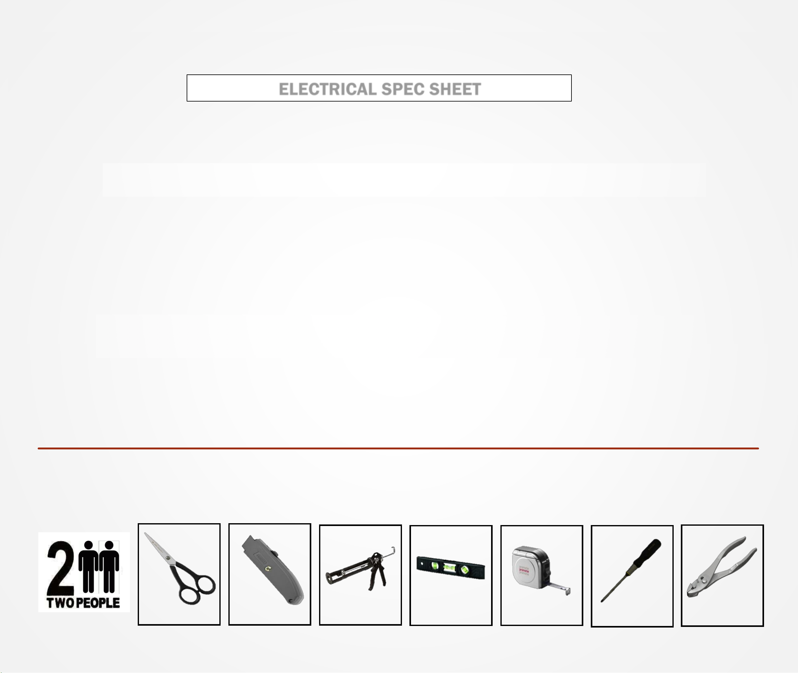
TOOLS NEEDED TO GET THE JOB DONE
Scissors Stanley Blade Silicone Gun Spirit Level Tape Measure Screwdriver Pliers
10
ELECTRICAL SPEC SHEET
5
ELECTRICAL SPEC SHEET
ELECTRICAL SPEC SHEET
5
ELECTRICAL SPEC SHEET
TOTAL ELECTRICAL REQUIREMENTS
Power Junction Box: 220V, 30 Amp
Two Water Pumps: 220V, 15 Amp
Page 7

CRATE CONTENTS
1. Crate# 1 (the large one)
1 - Whirlpool Bath Tub
1 - Roof
2 - Curved Rails (one black, one white)
2. Crate# 2 (the smaller one)
4 - Plastic Door Seals
2 - Glass Curved Doors (Large)
2 - Curved Glass (Medium)
2 - Curved Glass (Small)
1 - Left Black Glass Panel
1 - Right Black Glass Panel
2 - Aluminum Front (Wide) posts
2 - Aluminum Rear (Narrow) posts
1 - Main Back Panel Wall
1 - Bag of Installation Hardware
1 - Foot Massager
1 - Set of Clear Rubber Wedge Seal Strip (Small and Large)
1 - Set of “H” Shaped Rubber Glass Seal Strips (Small and Large)
2 - Magnetic Door Seal Strips
2 - Towel Bars
2 - Racks
11
Page 8
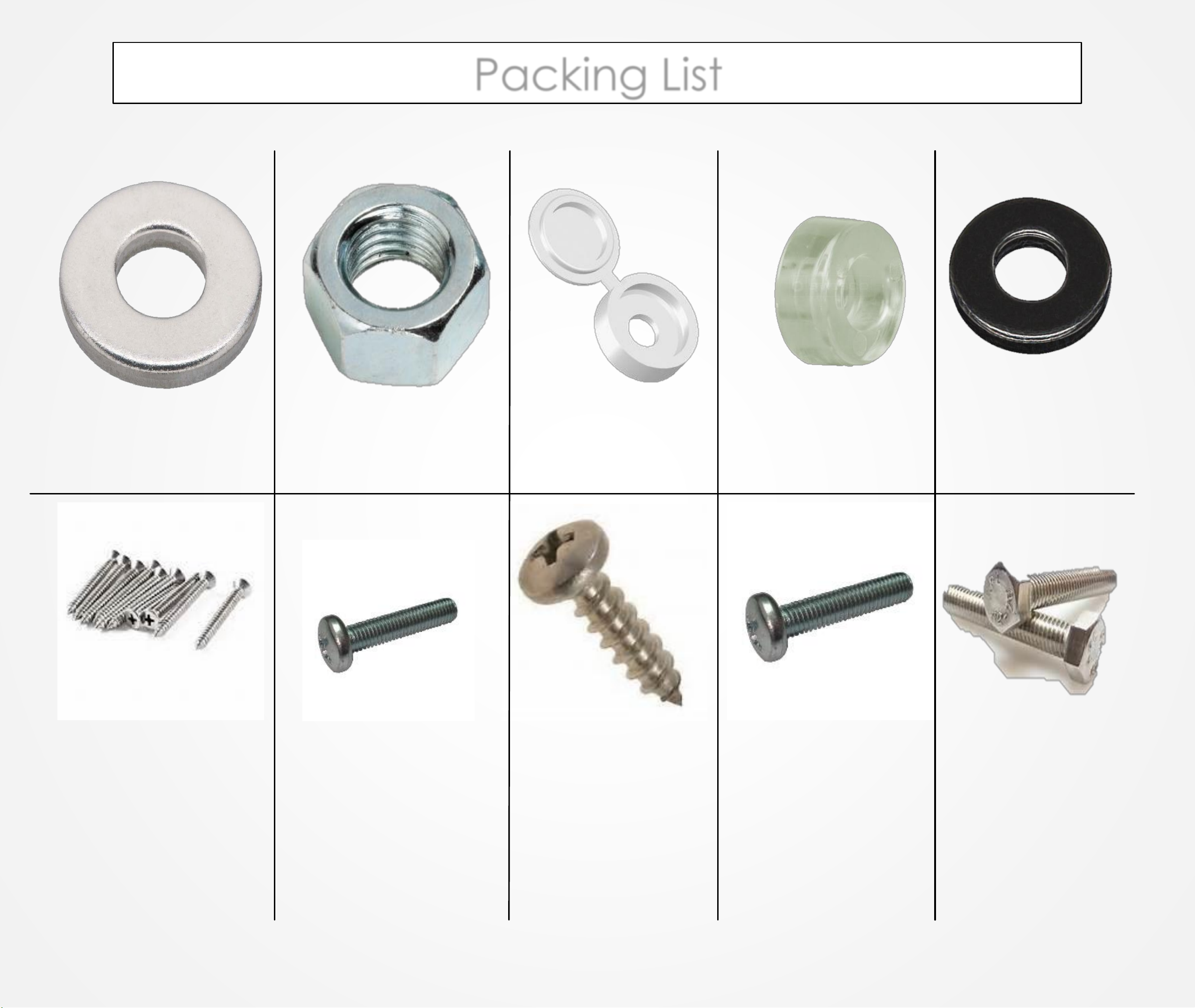
Packing List
PART# 1
#4 and #6 Flat
Washers
1 SET
PART# 3
Cap Screw Cover
Assembly
8 EA
PART# 2
#4, #5 and #6
Hex Nuts
1 SET
PART# 4
Clear Spacers
10 EA
PART# 5
Hose Seal Washer
6 EA
PART# 6
5/8” #4 Flat Head
Self-Tapping Screws
10 EA
PART# 9
1” #5 Pan Head
Machine Screws
8 EA
PART# 10
1 “ #6 Hex Machine
Bolts
10 EA
PART# 8
1" #6 Pan Head Self-
Tapping Screws
8 EA
PART# 7
1” #4 Pan Head
Machine Screws
3 EA
13
Page 9
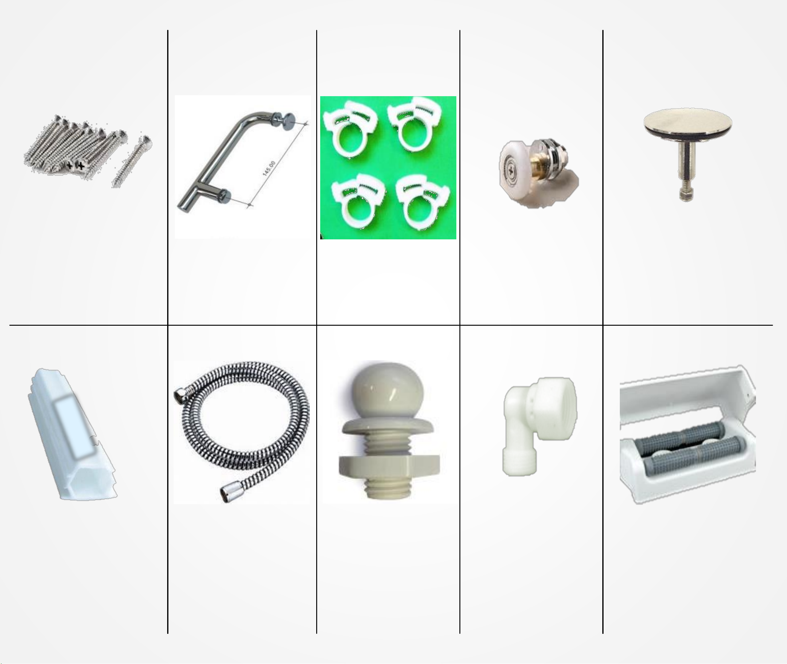
PART# 13
Hose Clamps
4 EA
PART# 14
Door Roller Wheels
8 EA
PART# 12
Shower Door
Handle
2 EA
PART# 15
Drain Plug
1 EA
PART# 16
White Rubber Seal/Stop
1 EA
PART# 18
Foot Massage
Adapters
2 EA
PART# 20
Foot Massager
1 EA
PART# 17
Shower Hose
3 EA
PART# 19
Foot Massager Hose
Adapter
1 EA
PART# 11
1" #4 Flat Head Self-
Tapping Screws
6 EA
14
Page 10
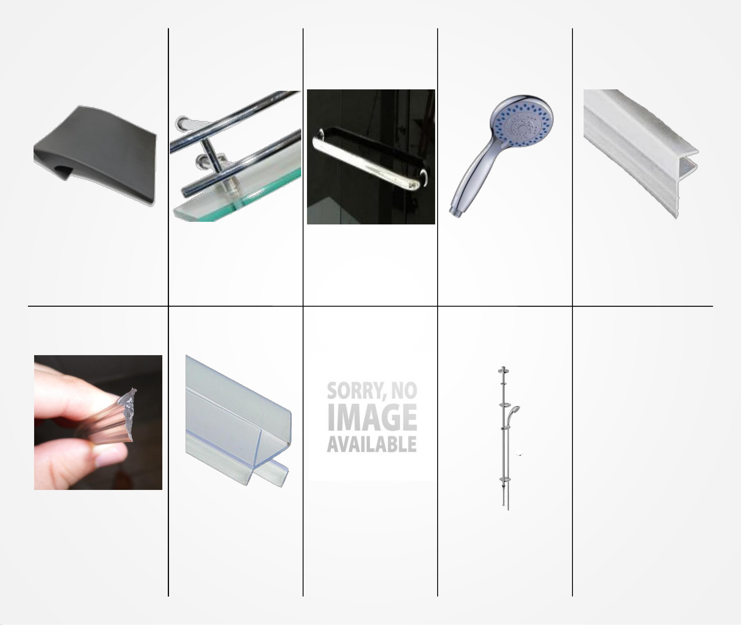
PART# 21
Back Rests
2 EA
PART# 23
Towel Bar
2 EA
PART# 24
Hand Held Shower
Head
2 EA
PART# 22
Shower Acc.
Rack
2 EA
PART# 25
Door Seals
4 EA
PART# 26
Clear Wedge
Window Seal Small
And Large
1 SET
PART# 28
Remote Control
1 EA
PART# 27
H Window Seal
Strips Small and
Large
1 SET
PART# 30
PART# 29
Shower Riser bar
2 EA
REMOVED
15
Page 11
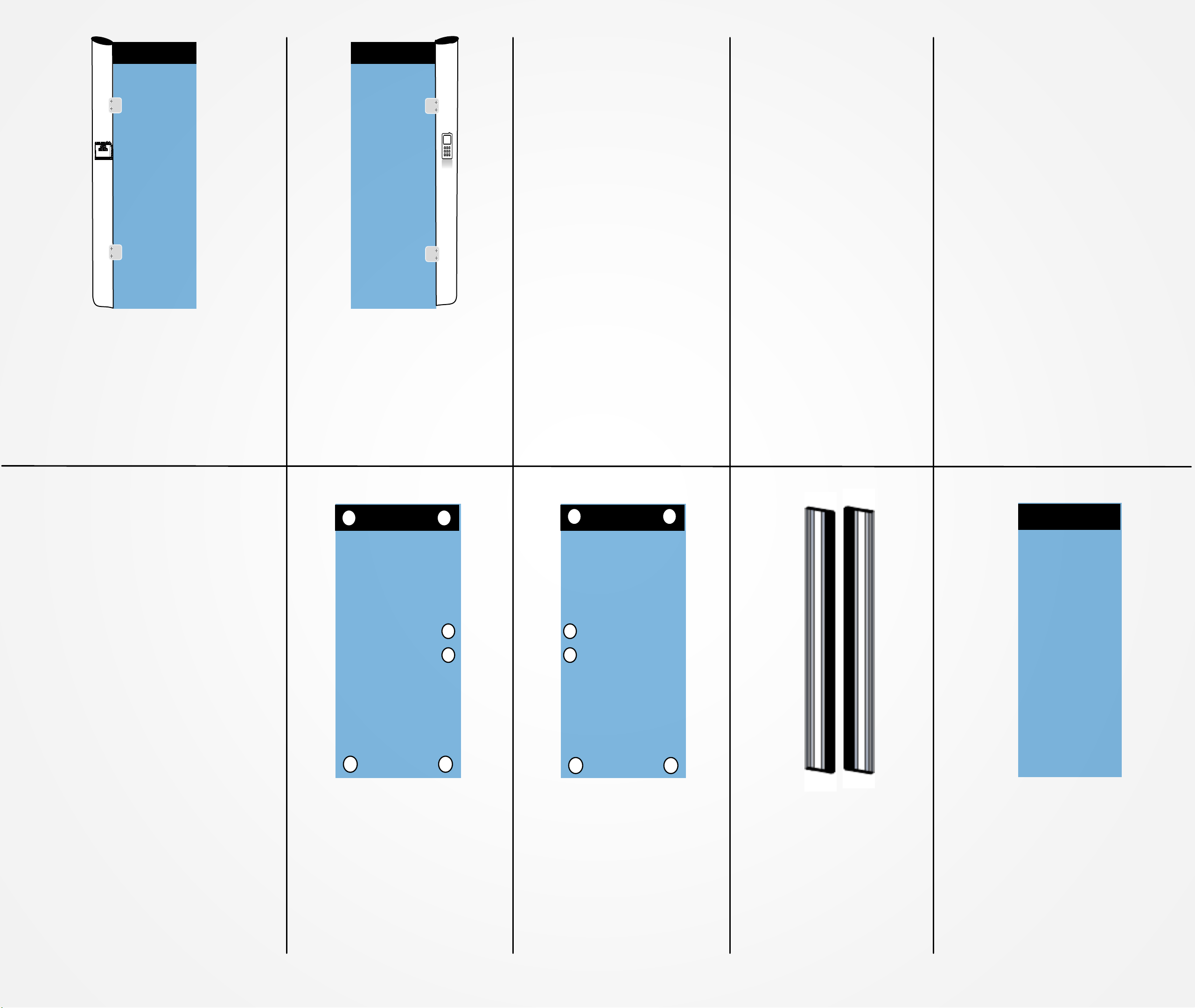
PART# 31
Left Upright Fixed Door
(Has Warning Sign on it)
1 EA
PART# 33
N/A
PART# 34
N/A
PART# 32
Right Upright Fixed Door
(Control Panel on it)
1 EA
PART# 35
N/A
PART# 36
N/A
PART# 38
Right Glass Door
(Sliding Door Units Only)
1 EA
PART# 39
Magnetic Door Seals
1 SET
PART# 37
Left Glass Door
(Sliding Door Units Only)
1 EA
PART# 40
Left Fixed Glass
1 EA
NOT APPLICABLENOT APPLICABLE
NOT APPLICABLE
NOT APPLICABLE
16
Page 12
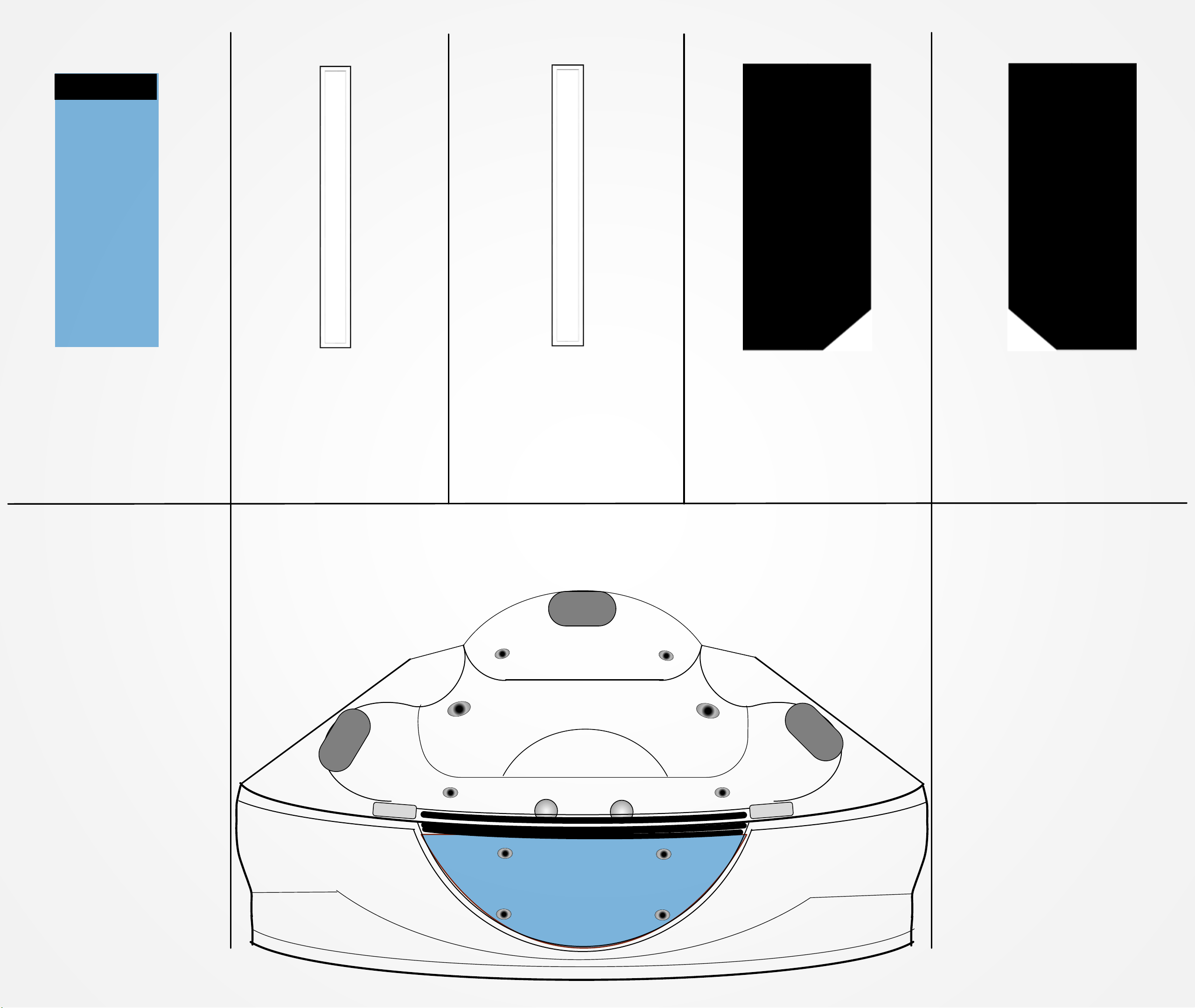
PART# 44
Left Back Glass
(Black)
1 EA
PART# 45
Right Back Glass
(Black) 1 EA
PART# 42
Left Rear Corner
Upright Aluminum Pole
1 EA
PART# 43
Right Rear Corner
Upright Aluminum Pole
1 EA
PART# 46
Whirlpool Tub
1 EA
PART# 41
Left Fixed Glass
1 EA
17
Page 13
Step 1
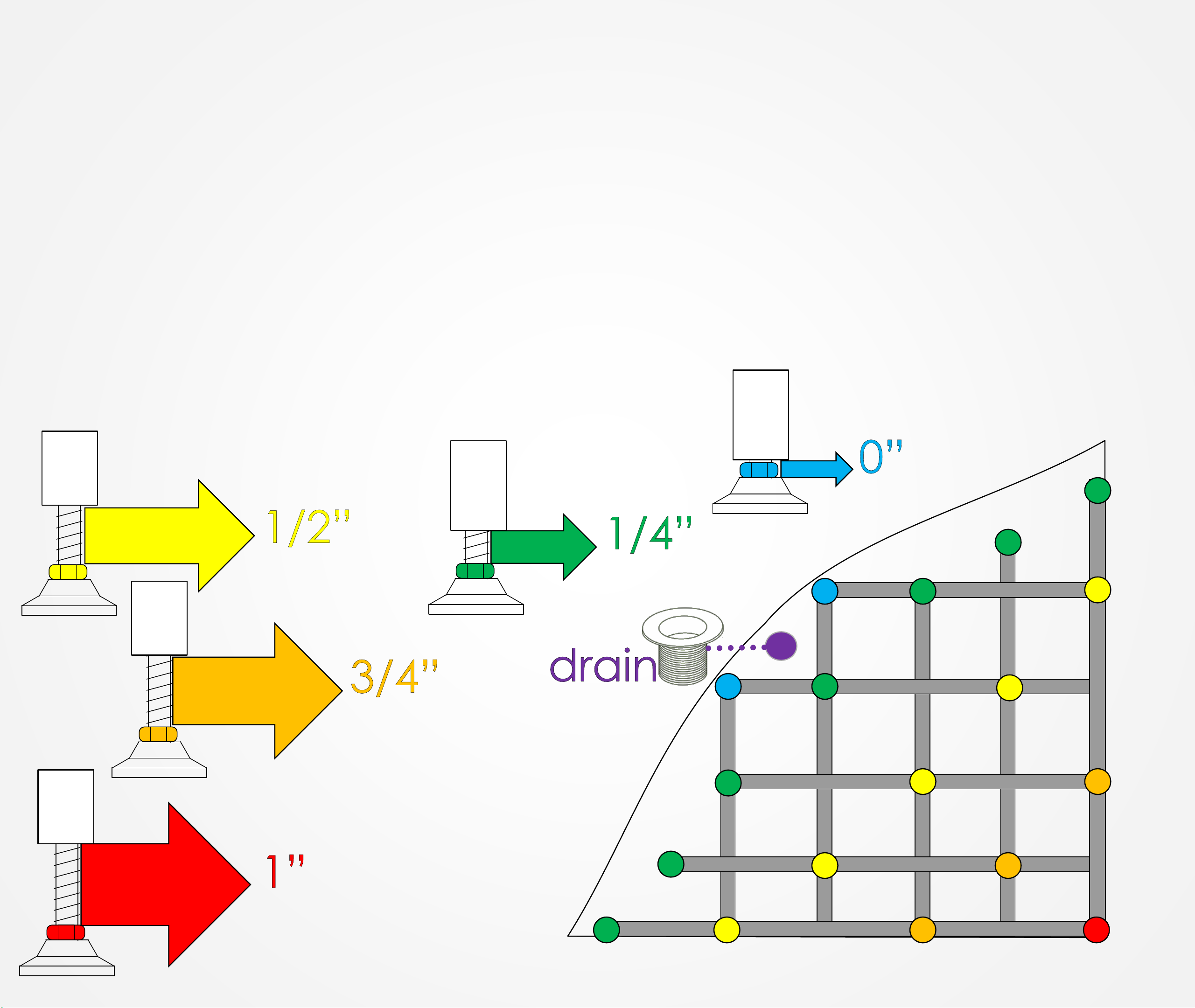
Level the tub by placing the tub carefully on its side (Warning! When placing unit on its side make sure make sure you do not put pressure on the acrylic
tub or any components contained underneath the tub).
Start by screwing all level locking feet clockwise to the inward position.
Then, Locate the furthest Level Locking Foot adjustment from the drain. Adjust those feet out one inch as shown in figure 2. As you move closer to the
drain, adjust the feet to three quarter inches, then, half inch, and finally one quarter of an inch, or all the way in, depending on tub. There is no science
behind this method and it takes in consideration that your floor is perfectly level. You may have to adjust according to your situation. The main goal is
to create a slopping plane for the water to roll off properly toward the drain.
With tub still on its side, Ensure the drain system is hand tight then apply a quarter turn of the wrench.
Should you need to change the drainage system or purchase any adapters; the waste drain is one inch and a half male fitting. Although it is not
required, changing the waste hose to a larger size is recommended for faster drainage.
Ensure all plumbing connections are tight. Use a wrench, if needed, to apply additional tightening. However, note that too much torque applied may
cause connections to crack and/or split. This is not covered by the warranty.
Place the tub carefully on its feet. DO NOT lift, drag or pull on the acrylic while setting the tub on its side or lowering it to its feet. Although the acrylic is
made of very sturdy strong material, you could still crack the acrylic. This is not covered by the warranty.
Then, use a Carpenter’s Level to make any minor adjustments to the tub.
Optional Step: Once Level, if you are able to fill with about an inch of water, fill and check the direction of the water drainage to ensure it is flowing
smoothly toward the drain.
Once the tub is level, you can proceed to Step 2, Pre-Fab. See Figure 1 in your manual.
18
Page 14
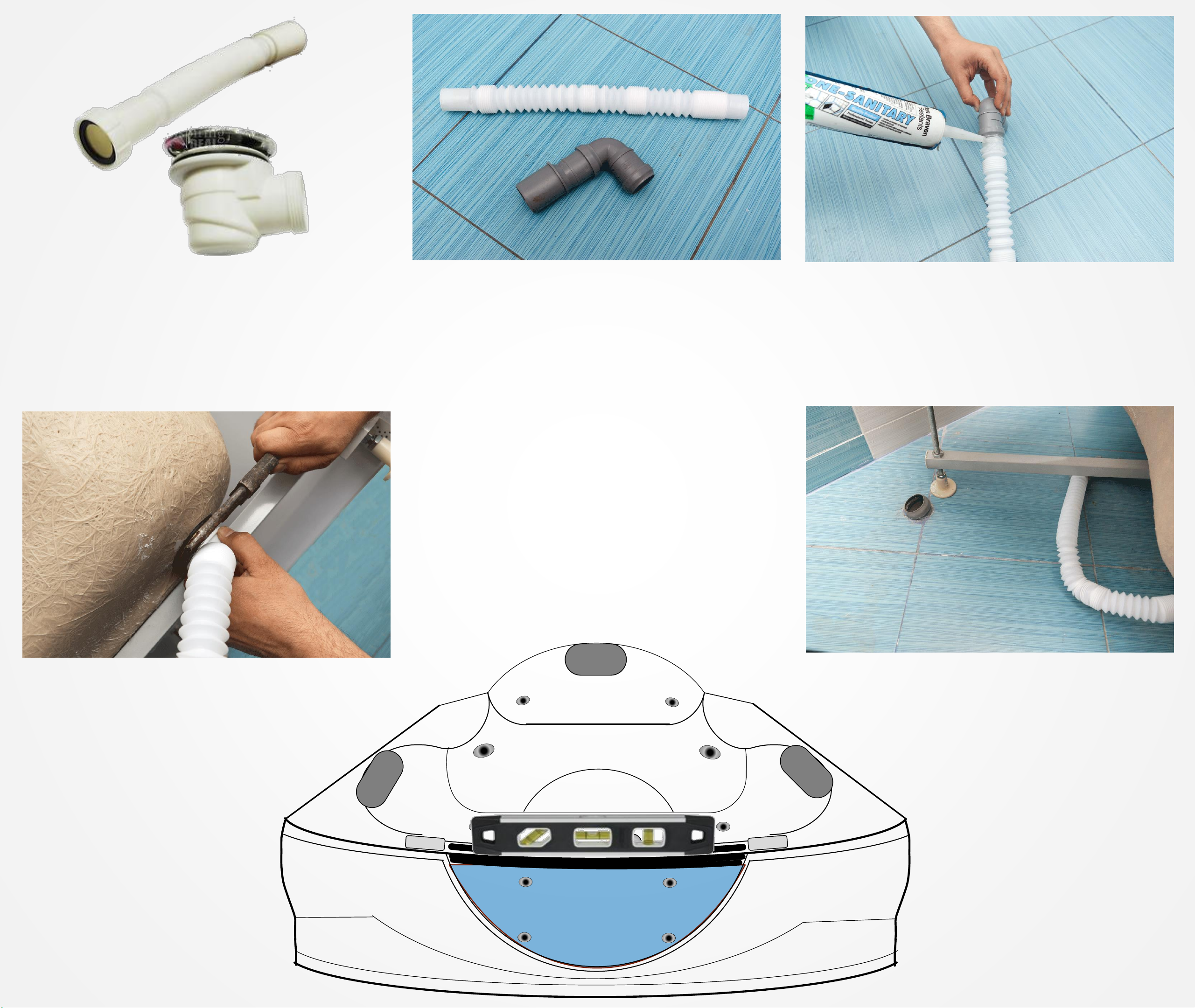
A. Connect the flex drain
hose to the drain
B. May need a 90 degree elbow to
connect to your homes waste
drain. Items pictured may be
different than what you have in
your crate and some you may
have to purchase at your local
hardware store.
C. Use silicone glue to secure your
adapter to your flex hose.
D. Ensure your drainage system
does not leak.
E. Make your final connection.
19
Page 15
Step 2
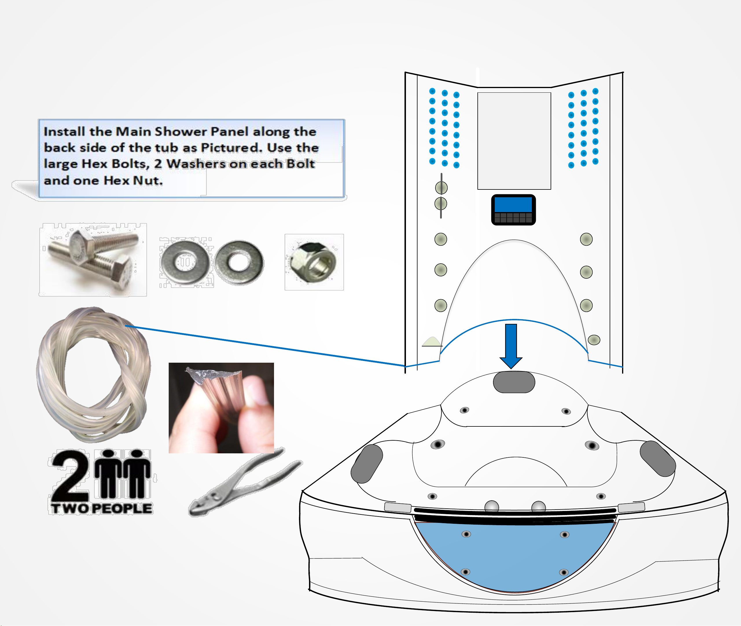
Parts Needed: Part# 1, 2 and 10
Tools Needed: Pliers, 6mm Wrench
Install The Main Shower Panel as depicted below. While placing
the main unit install the large clear seal wedge in between the
tub and the unit. Cut to fit. See the blue line for example.
20
Page 16
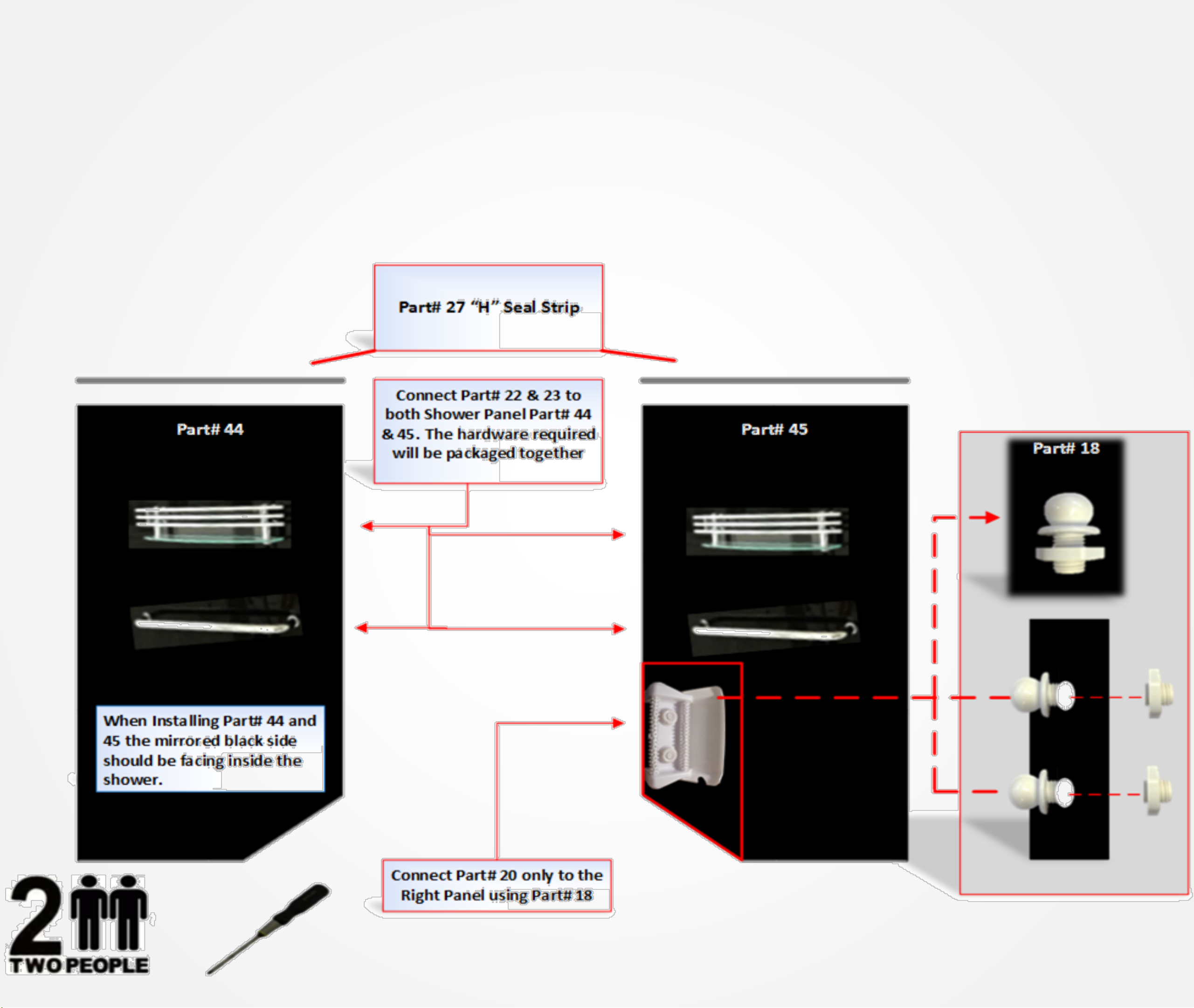
Parts Needed: Part# 18, 20, 22, 23, 27, 44 and 45
Tools Needed: Philips Screw Driver
Install the racks, towel bars and foot massager as shown
below.
Install the seal strip as shown below.
21
Page 17
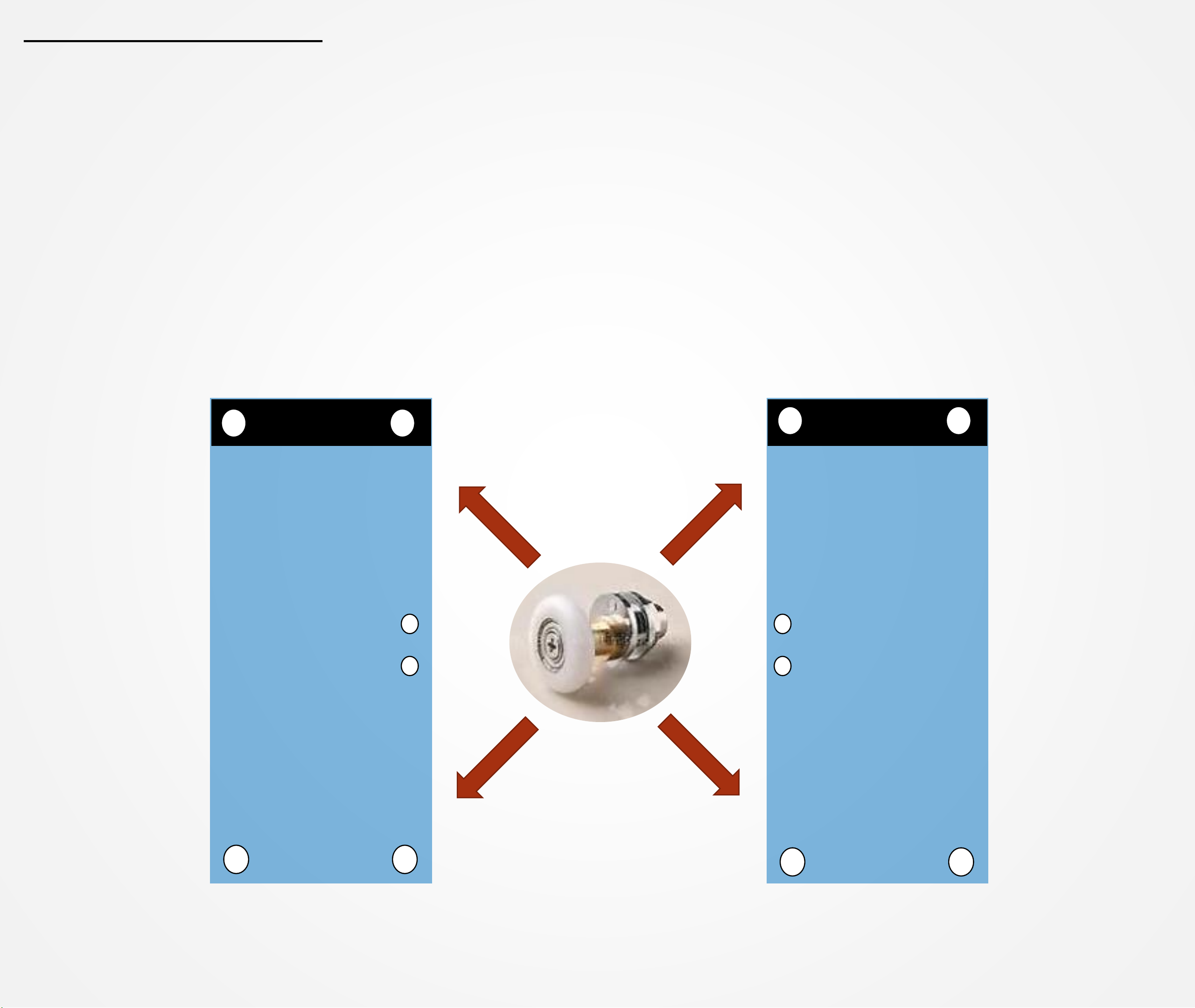
For Sliding Glass Doors Only
(If your shower door is a fixed door and does not slide open skip to page 25)
Parts Needed: Part# 14
Tools Needed: Pliers, Flat Head Screw Driver
a.) Install Part# 14 as outlined below. Pay attention to the mechanics of the roller wheel. Using a
straight screw driver will allow you to adjust the door up and down. Tightening the Hex Nut will lock it
into place. Finish by placing the metal cap on the end.
b.) After the wheels have been put on both top and bottom of the glass, place the top roller wheels
into the upper arch track section. Use a straight screw driver and turn the bolt until the glass is resting
in it’s lowest setting.
c.) Now place the lower roller wheels in the lower arch track section. Use a straight screw driver adjust
the wheels in the upward setting, as to make the wheels from top to bottom safely latch on to the arch
supports. Continually adjust top and bottom until the glass is level. Then lock in place using the Hex
Nut.
22
Page 18
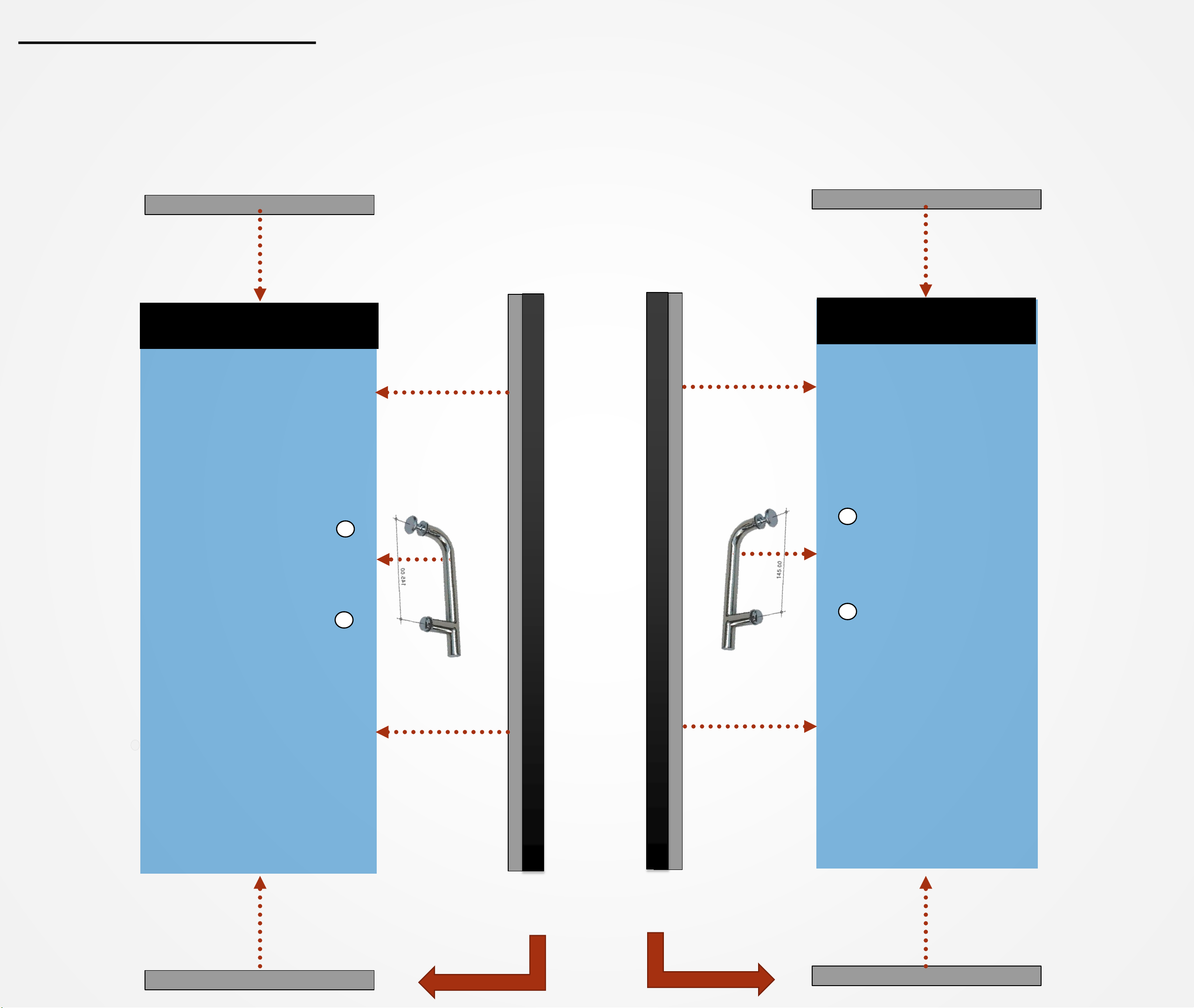
Sliding Glass doors only
(If your shower door is a fixed door and does not slide open skip to page 25)
Parts Needed: Part# 25, Part# 39, Part 12, Part# 37 and Part# 38
Tools Needed: Philips Screw Driver
a.) Install the side door seals and the Magnetic Door Seal. Next Install the Door Handles
MAGNETIC DOOR
STRIPS
#25 H SEAL STRIPS
23
Page 19
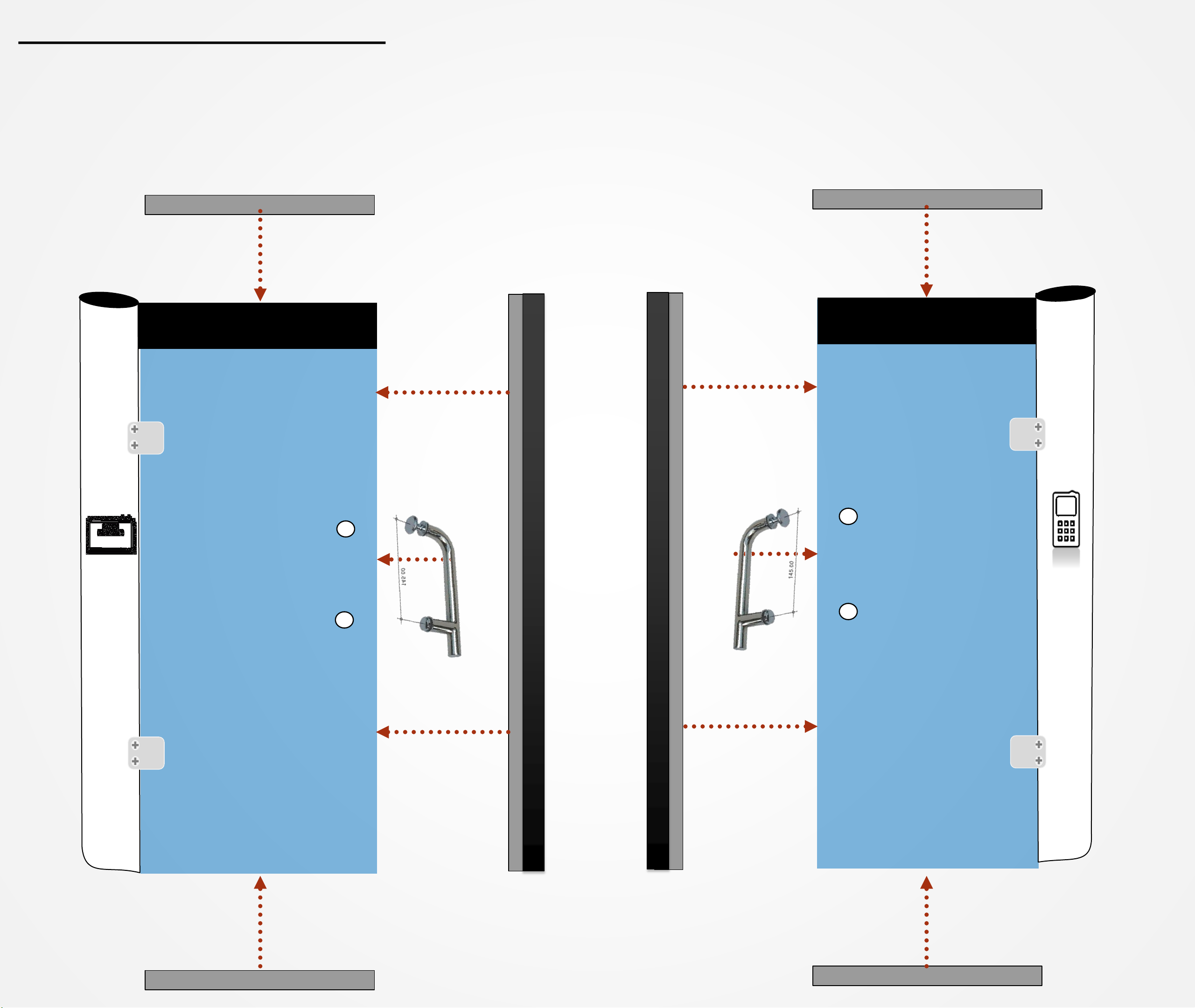
Fixed Door Applications Only
Parts Needed: Part# 25, Part# 39, Part 12, Part# 37 and Part# 38
Tools Needed: Philips Screw Driver
a.) Install the side door seals and the Magnetic Door Seal. Next Install the Door Handles
24
Page 20
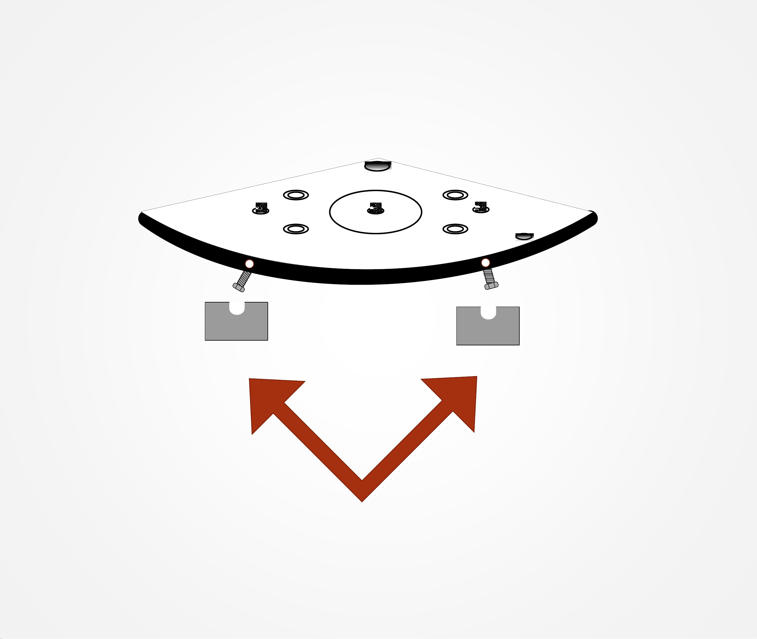
Remove Shower Retaining Brackets from the Ceiling. Do
no discard, you will use them in the next step.
25
Page 21
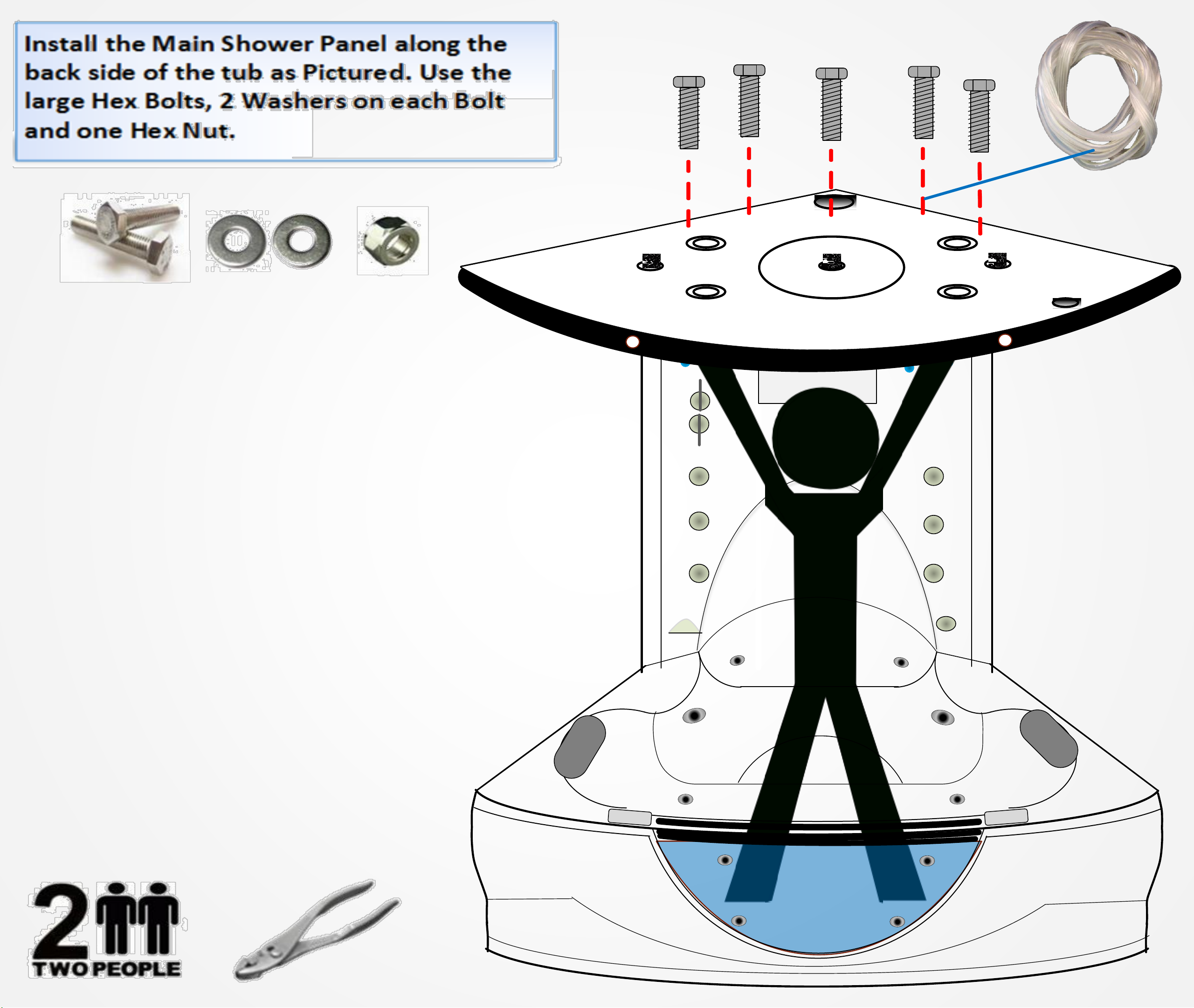
Parts Needed: Part# 1, 2 and 10
Tools Needed: Pliers, 6mm Wrench
Install The Main Shower Panel as
depicted below. While placing the
main unit install the large clear seal
wedge in between the tub and the
unit. Cut to fit. See the blue line for
example.
26
Page 22
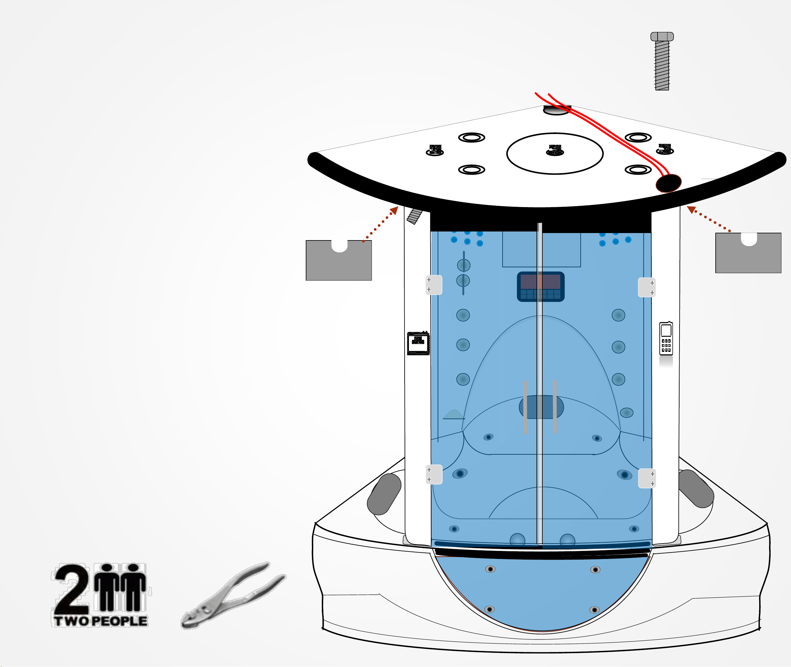
Tools Needed: Pliers
Secure the Fixed showers
doors by clipping into the
grey tub mounting
brackets on the tub.
Then, using the ceiling
mount retaining
brackets, slide the metal
bracket into the pole and
the screw through the
hole in the ceiling. Then
screw them together.
27
Page 23
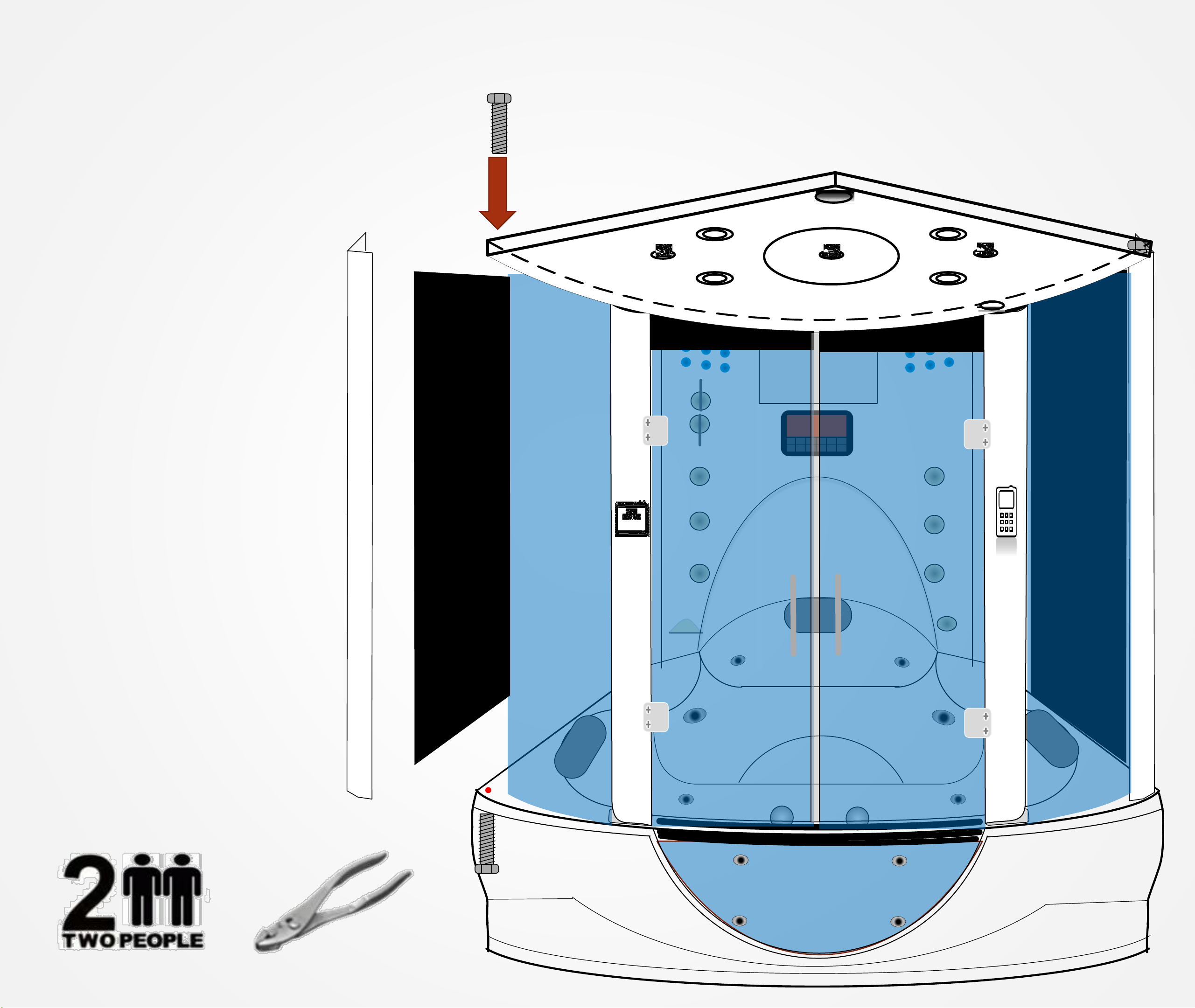
Tools Needed: Pliers, Screw
Driver
A. Place part number (40),
Left fixed glass in.
B. Then, part number (42),
the back corner post in.
Making sure the hex nut and
washer are removed before
placing the corner posts in.
C. Reattach the Washer and
Hex nut on the underside of
the tub to the screw insert
on the back corner post.
D. Slide the Left fixed glass
into the back corner post
channel first.
Slide part number (44), the
Black Glass section into the
Main Shower Control Panel.
(The end without holes
should be the end that slides
into the channel on the
Main Shower Control Panel).
Then, Place the Black Glass
with the hole side against B.
E. Bolt B into the ceiling
section of the shower top.
Finally, repeat the process
on the opposing side.
A
B
C
D
E
28
Page 24
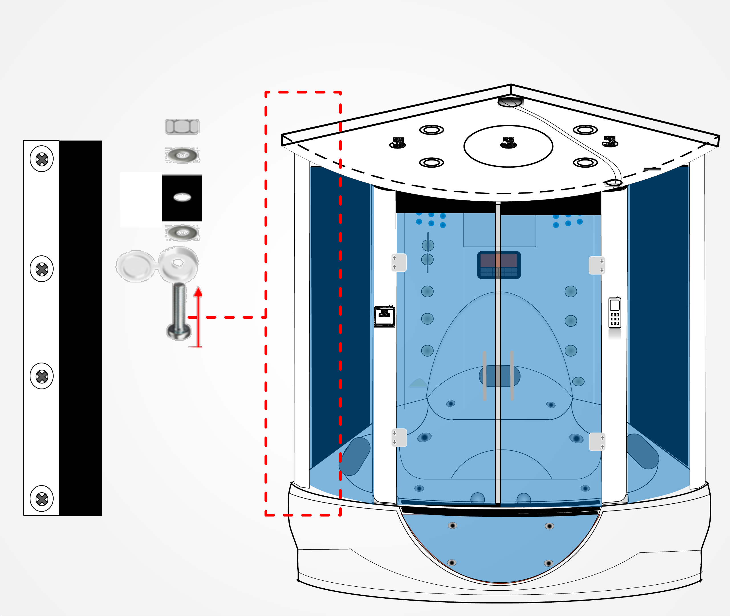
Using part numbers (1),(2), (3) and (9), assemble the black glass to the back corner
posts. If the holes do not line up, then you may have the wrong back corner post. Stop
and switch rear posts.
29
Page 25
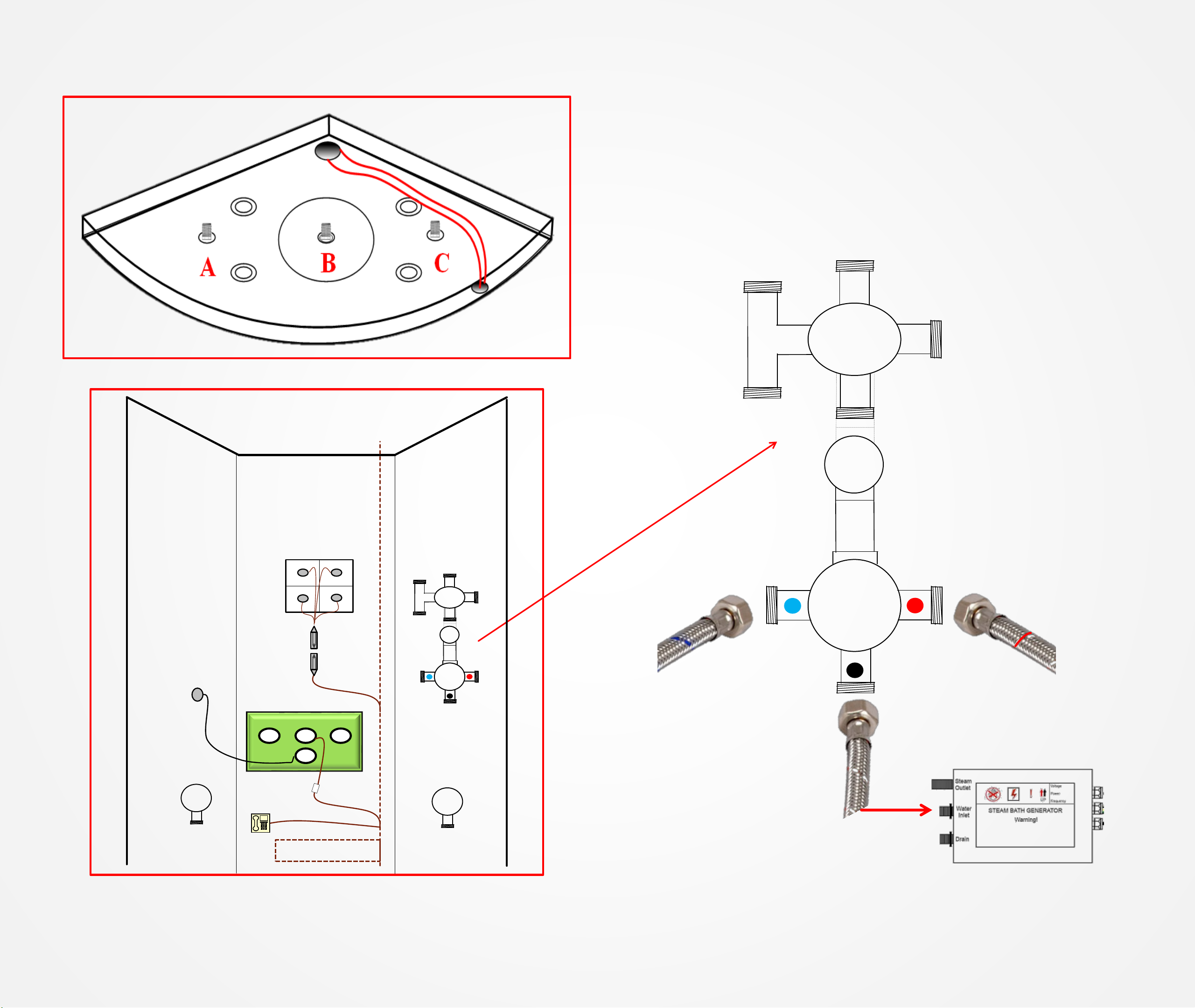
Input: Steam Cold
Input
Input: A
Input: D
Input: B
Input: E
Input: C
Input: Hot Water
Supply
Step 10 Hose Connection
Diagram
Use Plumbers Tape on your final pipe connections
See note 1 for Valve Identification
Input: Cold Water
Supply
D
E
Back of Unit
D
E
Spray
Controller
LCD Panel
Water Valve
Diverter
G
G4
G1
G2
G3
F4 Cable
LCD Power
Temp Probe
Click Anywhere to begin
30
Page 26
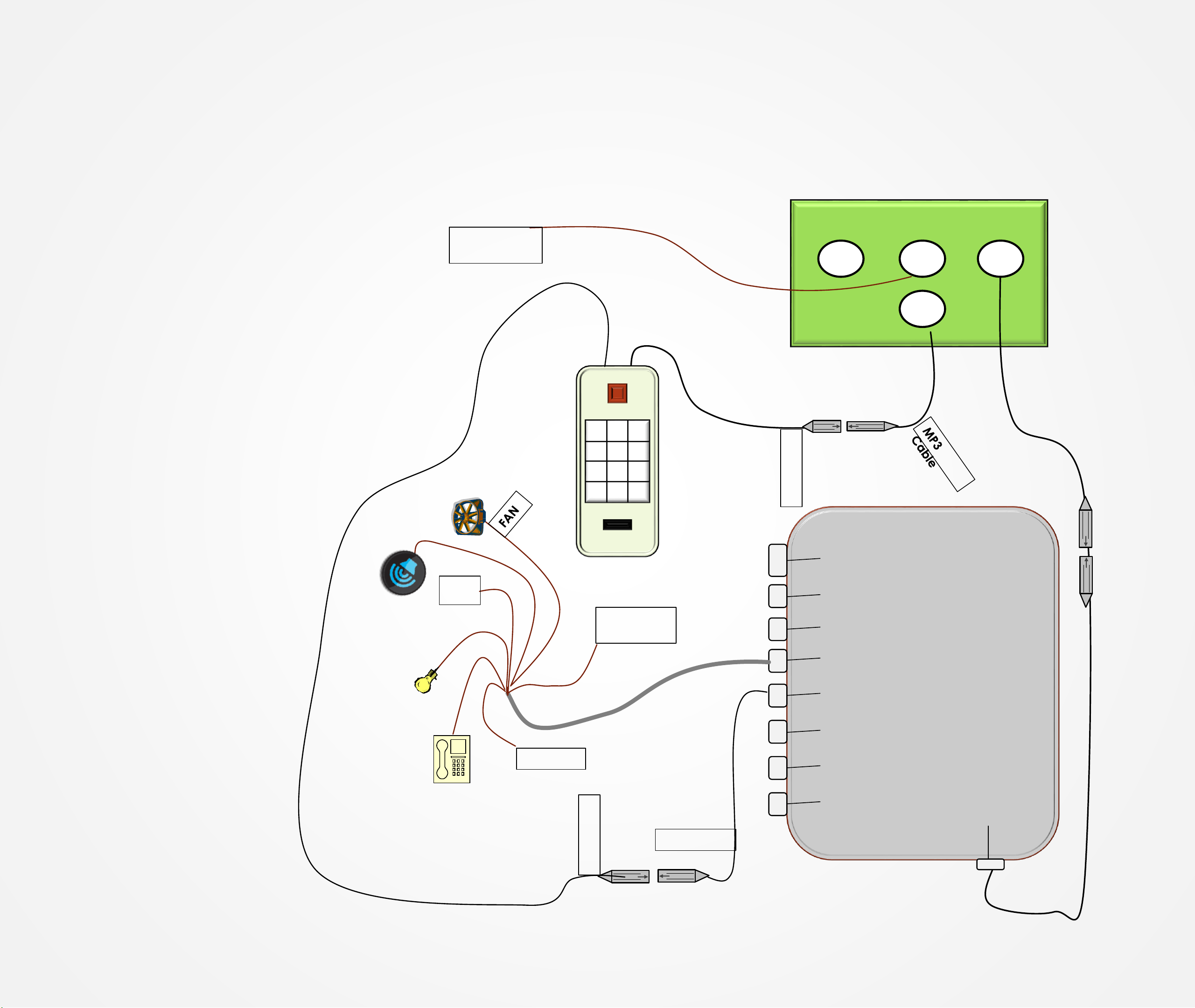
MP3 Cable
H
Tools Needed: Small Philips Screw Driver
F1 = To Power Supply 220V 30A Outlet
F2 = No actions required
F3 = No actions required
F4 = To top of shower Ceiling
F5 = Connect the USB to
F6 = No action required
F7 = No action required
F8 = No action required
F9 = To LCD Screen connection G3
G1 = To Satellite, Cable Box or other TV
Source
G2 = LCD Power, AV Cable for DVD
Player, Temp Probe (See Step 12 cont.
Diagram), G4 Connection from H
G3 = Junction Box Connection
G4 = MP3 Connection from H Control
Panel, Tub Temp Probe (See Step 11
Diagram)
G
LCD Screen Rear View
G4
G1
G2
G3
Junction Box
F
F4 Top of Shower Roof
F5
F6
F3
F2
F1
F7
F8
F9
USB Cable
USB Cable
To Tub Temp
Probe
F4
Cable
goes to
shower
ceiling
O3
LCD
Power
To Spray
Controller
Electrical Connections
31
Page 27
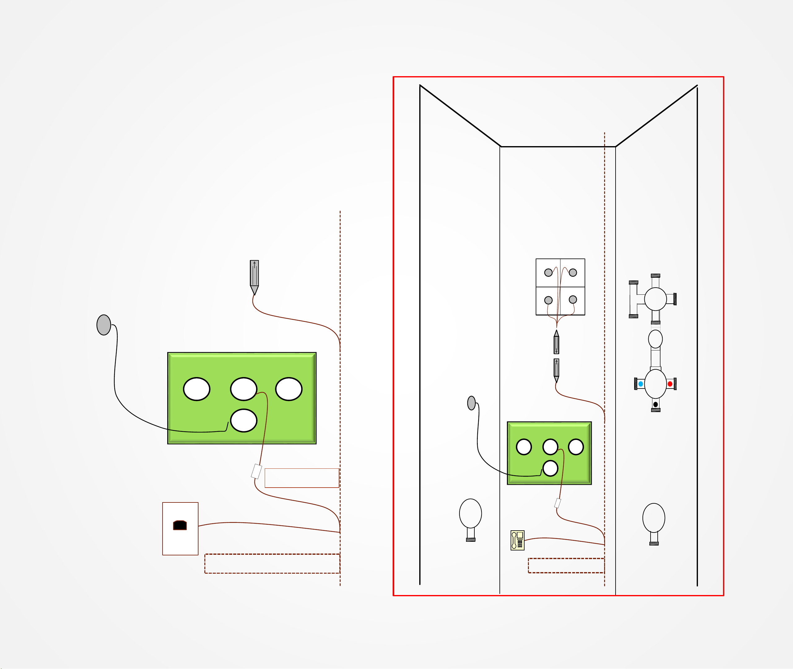
Back of Unit
Spray Controller
LCD Panel
Water Valve
Diverter
G
G4
G1
G2
G3
F4 Cable
LCD Power
Temp Probe
Tools Needed: Small Philips Screw Driver
G1 = To Satellite, Cable Box or other TV Source
G2 = LCD Power, AV Cable for DVD Player, Temp Probe
(See Step 11 Diagram), G4 Connection from H
G3 = Junction Box Connection
G4 = MP3 Connection from H Control Panel, Tub Temp
Probe
(See Step 11 Diagram)
LCD Panel
G
G4
G1 G2
G3
F4 Cable
LCD Power
Temp Probe
Phone Outlet
Cont. Electrical Connections
32
Page 28
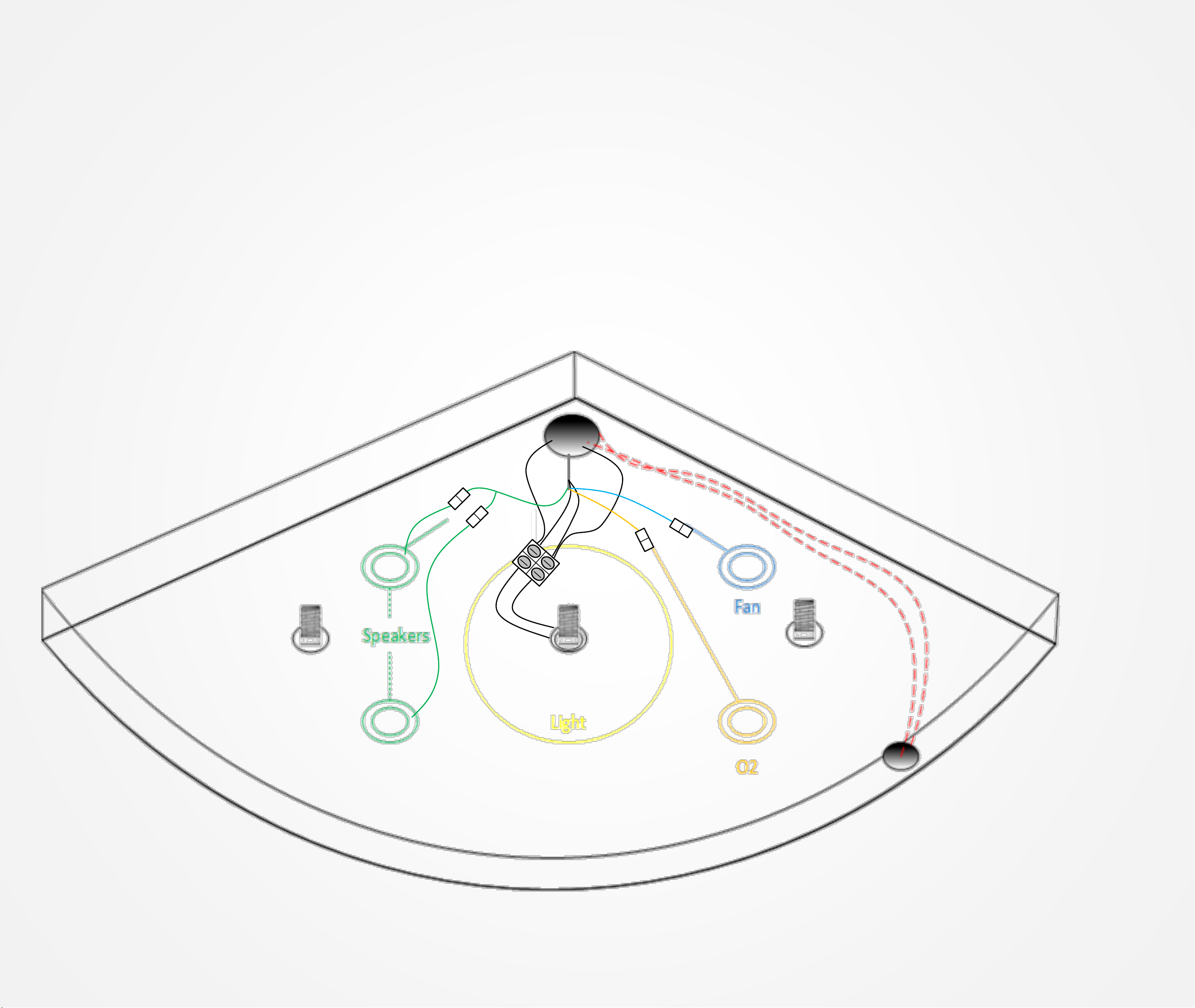
Top Electrical Connections
Tools Needed: Small Philips Screw Driver
Using the F4 Cable from the Junction Box, run the cable through the holes provided all the way up to the shower
ceiling.
Each cable from each device will have an identifying label on what to connect to. See diagram Below.
See Step 13a for light connections.
The lights will have a 4 bar screw connector.
On the back of the Main Shower panel is two cables one coming from each of the LED lights on the main shower
panel. Run these cable to the ceiling.
Using those two cables and the light cable coming from the top middle of the shower, hold all of the solid red lines in
one hand and twist them together. Then do the same thing separately to the red and black wires.
33
Page 29
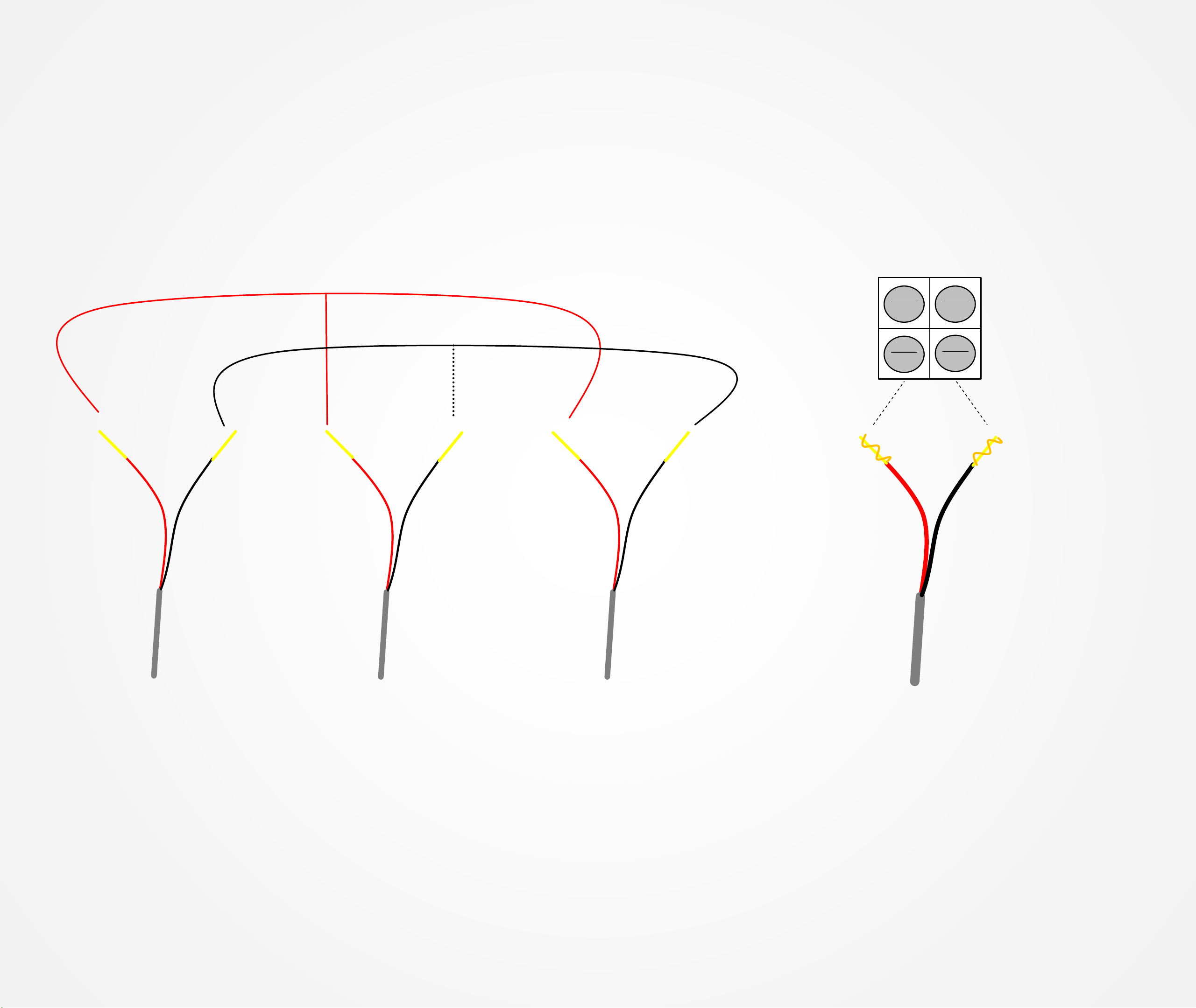
Cont. Light Connections
Tools Needed: Small Philips Screw Driver
The lights will have a 4 bar screw connector.
On the back of the Main Shower panel is two cables one coming from each of the LED lights on the main shower
panel. Run these cable to the ceiling.
Using those two cables and the light cable coming from the top middle of the shower, hold all of the solid red lines in
one hand and twist them together. Then do the same thing separately to the red and black wires. When complete
connect the wires inside the block matching the colors of the wires on the opposite side.
Cable from
LED Light on
back of main
shower panel
Cable from
LED Light on
back of main
shower panel
Cable from
LED Light on
top of shower
ceiling
All three
cables twisted
together
34
Page 30
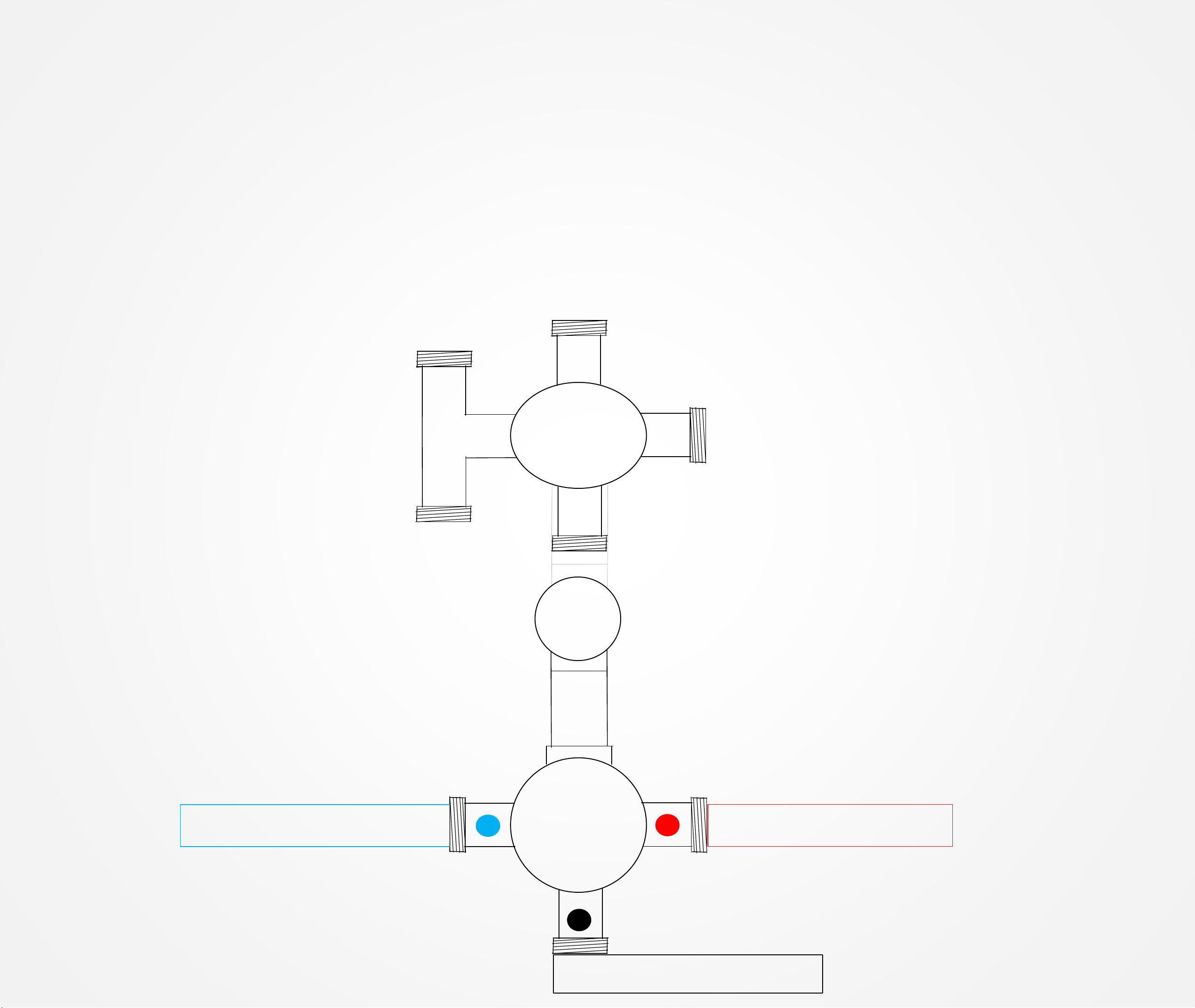
Rain Shower Head
Tub Fill Spout
Top Shower Head Left
Top Shower Head Right
Foot Massager
Hot Water Intake
Cold Water Intake
Steam Gen Output
Note 1 Water Valve Identification
Tools Needed: N/A
IF YOUR DIAL DOES NOT CORROSPOND TO THE APPROPRIATE DEVICE:
Turn on your water to the shower and note which output the water exits from then turn off the water and swap over
the relevant hose.
Alternatively remove the outer chrome knob by removing the chrome cap and loosening the grub screw (please
ensure not to unscrew fully as this will drop within the chrome knob) this is found on the opposite side to the chrome
pillar. Once you have succeeded in loosening this you can now slide your faceplate to correspond to the device.
35
Page 31

TESTING FOR WATER LEAKS
DO NOT USE SHOWER 24 HOURS AFTER BUILD TO ALLOW SEALENT TO CURE
With all connections tight, the waste and hoses checked, jets fully sealed, your shower still around 18 inches from
its designated final resting point and the silicone fully cured (hence leaving for 24 hours minimum) Switch on the
overhead shower NOT the massage jets, remember these will fire water out at you and are not suitable for
checking leaks as they would normally only operate when a person is in front of them. Just use COLD water setting
as hot will make cabin misty and condensate thus the inspection becomes very difficult. Now on the OUTSIDE of
the shower inspect each joint, factory seal, hose, clip and jet by walking from one side and going around to the
back and then to the other side finishing at the front. If you have a small leak (normally caused through
insufficient sealer or air bubble on assembly, dry the area thoroughly and reseal on the OUTSIDE. Please remember
where you see the water this may not be exactly where the leak is as it could have run around to a low point.
Never seal your inner fittings (accessories) inside unless you feel it necessary and make sure it is thin and neat,
remember you will see this for the life of the shower!
Again leave to cure and check. If all good now check shower functions i.e. jets for back massage, foot massage,
(if you have one) and finally hand shower, check your joints to these functions at the rear again. Never use the
shower until all checks have been made and the installer is 100% happy in the knowledge no leaks are present. All
good?
Now push your shower FROM THE BASE NEVER PUSH FROM THE GLASS OR FRAME into its final resting position. Now
you can shower in the knowledge that you have no leaks a job done well and long product life.
Happy showering!
Need Help
 Loading...