

Page 1
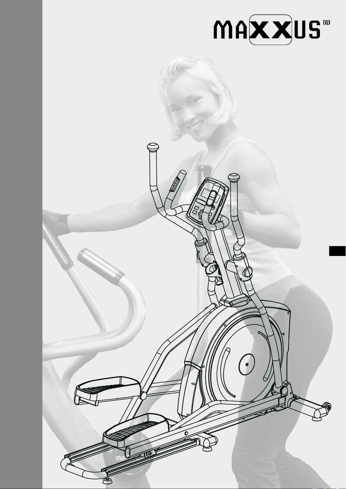
MAXXUS CX 5.1
Cross-Trainer
ENG
INSTALLATION & OPERATING MANUAL
Page 2

Index
Index 2
Safety Instructions 3
Overview of the Device 4
Scope of Delivery - Box A 4
Scope of Delivery - Box B 5
Fixing Materials and Tools 5
Assembly 6 – 11
Transport, Location and Storage 11
Maintenance and Care 12
Levelling the Device 12
Mains Cable 13
Cockpit 14 – 21
Pulse & Heart Rate 22 – 23
Training Recommendations 24 – 25
Technical Details 26
Dimensions 26
Disposal 26
Exploded Drawing 27
Parts List 28
FAQ 29
Recommended Accessories 29
Warranty 30
Service Contract 31
© 2019 MAXXUS Group GmbH & Co. KG
All rights reserved / All rights reserved
This publication may not be reproduced, stored in a retrieval system, or transmitted in whole or in part, in any form or by any means, electronic,
mechanical, photocopying, recording, or otherwise without the prior written permission of Maxxus Group GmbH & Co. KG.
Errors, colour and technical modication subject to change, reproduction as well as electronic duplication only with written permission of MAXX-
US Group GmbH & Co. KG.
2
Page 3
Safety Instructions
Before you start exercising, be sure to read the entire user guide, especially the safety information, the maintenance & cleaning
information and the training information. Take care too that everyone who uses this training device is also familiar with this information and observes it.
Be sure to carefully follow the maintenance and safety instructions in this manual.
This training device may only be used for its specic purpose. Improper use may present a risk of accidents, damage to health or
damage to the exercise device. No liability whatsoever is accepted by the distributor for injury or damage caused by improper use.
Power connection (only applies to devices with an external electrical connection)
− A mains voltage of 220-230V is required for the operation of the device.
− The exerciser may only be connected to a professionally installed, earthed, 16 A, fused single socket with the mains cable
supplied.
− The training device is switched on and o only using the ON / OFF switch.
− Always disconnect the power plug from the power outlet when moving the exerciser.
− Before carrying out any cleaning, maintenance or other work, always disconnect the mains plug from the socket.
− When connecting the mains plug, do not use socket strips or cable reels.
− If an extension cable is required, then it must comply with DIN standards, VDE regulations and guidelines, technical rules
issued by other European Union member states or other states which are party to the Agreement on the European Economic
Area.
− Always lay the power cord in such a way that it can neither be damaged nor is a tripping hazard.
− In operating or standby mode, electrical devices such as mobile phones, PCs, Televisions (LCD, plasma, tube, etc.), game
consoles etc. will emit electro-magnetic radiation. For this reason, all these types of devices should be kept away from your
training device as they could lead to malfunction, disturbances or false outputs being shown in heart rate measurements.
Training environment
− Select a suitable space for your training device to provide an optimum amount of free space and highest level of safety. You
should leave a free space of at least 100 cm in front of and behind the device and a minimum of 100 cm to each side of the
training device.
− Ensure good ventilation and that optimal oxygen is available during exercise.Avoid draughts.
− Your exercise equipment is not suitable for outdoor use, so storage and training is only possible in temperate, clean dry
rooms.
− Do not operate or store your training device in wet areas, such as swimming pools, saunas, etc.
− Make sure that your exercise equipment is always mounted on a level clean surface is. Unevenness in the ground must be
removed or compensated.
− To protect delicate oors, such as wood, lamina, tiles, etc. and from damage such as scratches, it is recommended to put a
oor protection (carpet piece, mat, etc.) permanently under the device. Make sure that the pad is secured against slipping.
− Do not place the exerciser on pale or white carpets, as the feet of the appliance may cause marks.
− Make sure that your exercise equipment, including the power cord, does not come into contact with hot objects and there is a
sucient safety distance from any heat source, such as radiators, stoves, open replaces, etc.
Personal safety instructions for training
− Remove the batteries or mains cable (if present) when the training device is not in use to avoid inappropriate or uncontrolled
use by any other third party, e.g. children
− You should make a health check with your doctor before your rst workout.
− If you feel any physical discomfort or experience breathing problems, stop training immediately.- Always start your workouts
with a light load and increase it during the course of your workout evenly and gently. Reduce the load towards the end of your
training session.
− Be sure to wear suitable sportswear and sports shoes during exercise. Note that loose clothing can get caught in the running
belt or rollers during exercise.
− Your exercise equipment can only be used by one person at a time.
− Check whether your device is in perfect condition before every training session. Never use your exerciser if it has any faults
or defects.
− Independent repair work can only be done after agreement and approval from our service department has been received.
Only original spare parts may be used.
− Your exercise equipment must be cleaned after each use. In particular, remove all residues caused by body perspiration or
other liquids.
− Always make sure that liquids (drinks, body sweats, etc.) never enter the vibrating plate or penetrate the cockpit, as this leads
to corrosion and damage to the mechanical and electronic components.
− Your exercise equipment is not suitable for use by children.
− During training, third parties - especially children and animals - must have a sucient safety zone.
− Before any training, check whether there are objects under your training device and remove them. Never exercise with your
exerciser when there are objects underneath.
− Always make sure that your exerciser is not misused by children as a toy or climbing equipment.
− Make sure that you and third parties never bring body parts close to moving mechanisms.
ENG
The construction of this training device is based on state-of-the-art technology and highest modern technical safety standards.
This training device is to be used by adults only! Extreme misuse and/or unplanned training can cause damage to your health!
3
Page 4
Overview of the Device
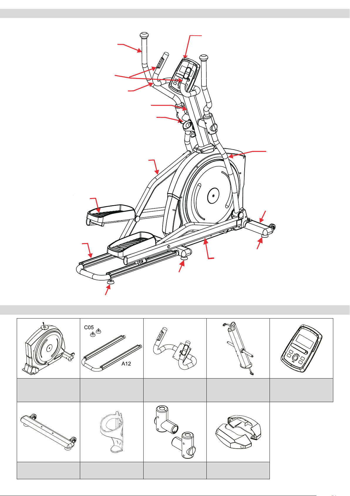
Pendulum handlebar
Hand pulse sensors
Fixed Handlebars
Cockpit
Handlebar Stem
Bottle holder
Pendulum tube
Pedal Tube
Pedal
Slide Frame
Height adjustable foot
Scope of Delivery – Box A
Stand with
Transport Roller
Height adjustable foot
Guide Tube
Height adjustable foot
A01
Main Frame
A09
Stand
A12 Slide Frame
C05 Floor Level Ad-
justment
C27
Bottle Holder
A16
Fixed Handlebars
C17/C18 Covers for
Pendulum Handlebars
4
A02
Handlebar Shaft
C07/C08 Covers for
Handlebar Shaft
D02
Cockpit
Page 5
Scope of Delivery – Box B
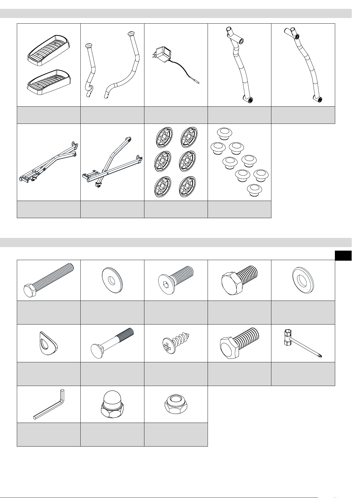
C12
Pedals
A05/A07 Pedal Arm &
Guide Tube, left
A13/A14
Pendulum Handlebars
A06/A08 Pedal Arm &
Guide Tube, right
D08
Mains Adapter
C11
Caps, round
A03
Pendulum Tube, left
C14
Caps for Treads
Fixing Materials and Tools
A04
Pendulum Tube, right
ENG
(1) Hexagonal Screw
B20 3/8"x64
2 pcs
(6) Curved Washer
B28 M8x20x1.5
4 pcs
(11) Allen Key M5
1 pc
You are welcome to supplement or replace the supplied tools with your own. Make sure that any tools you use are an accurate t.
(2) Washer
B33 5/16"x20x2.0
4 pcs
(7) Carriage bolt
B28 M8x50mm
4 pcs
(13) Cap Nut
B22 3/8"
2 pcs
(3) Allen Screw
B41 M8x25mm
2 pcs
(8) Tapping Screw
B40 M5x16mm
10 pcs
(14) Lock Nut
B29 M8
4pcs
(4) Hexagonal Screw
B32 M8x16
4 pcs
(9) Hexagonal Screw
B44 M8x20mm
4 pcs
(5) Washer
B21 3/8"x20x2.0
4 pcs
(10) Phillips Screw-
driver & Wrench 13/14
5
Page 6
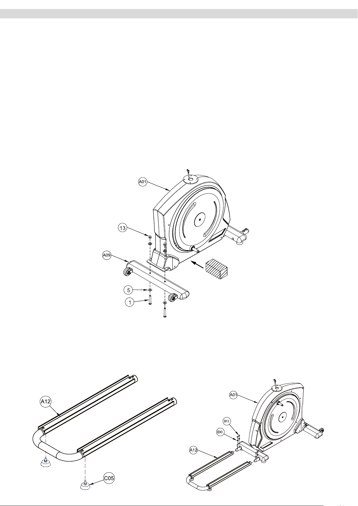
Assembly
Carefully unpack all parts of the delivery. Two people are required because some parts of your exercise machine are bulky and heavy. Before starting, check the completeness of the fastenings (screws, nuts, etc.) and
the components in the parts and assembly materials listed on the previous pages of this manual.
Carefully carry out the installation, as damage or defects that have arisen due to assembly errors are under
not covered by the warranty under any circumstances. Read the instructions carefully before starting, follow
the sequence of the installation steps exactly and follow the instructions for each individual assembly step. The
installation of the training device must be carried out by responsible adults.
Carry out the assembly of your exercise equipment in a location that is level, clean and free from obstructions.
Carry out the assembly with 2 people. Only after the installation of your training device has been completed can
training be started.
Step 1: Assembling the Stand
To make it easier for you to assemble the stand (A09), slide a support (eg a Styrofoam block from the packaging) under the main frame – see picture below.
Then attach stand (A09) to the front of the main frame (A01). To do this use two hexagonal screws 3/8”x64mm
(1), four washers 3/8”x20 (5) and two cap nuts 3/8” (13).
Step 2: Assembling the Slide Frame
Attach the two stand feet with oor level adjustment (C05) to the rear end of the slide frame (A12).
Before you assemble the slide frame (A12) please loosen and remove the four Allen screws M8 (B13) and the
four curved washers M8 (B30) which are pre-assembled on the rear mount of the main frame (A01). Then x
the slide frame (A12) to the rear mount on the main frame (A01) using the four Allen screws M8 (B13) and four
curved washers M8 (B30) just removed.
6
Page 7
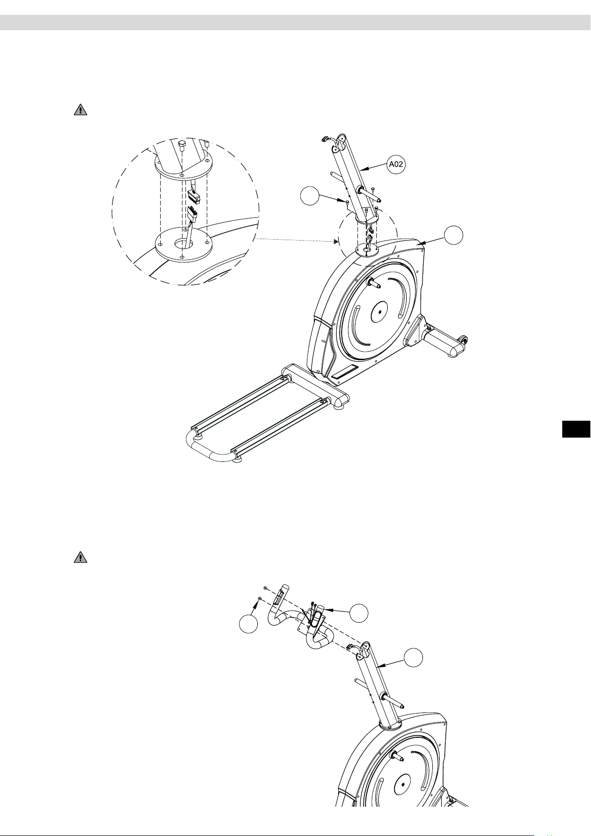
Step 3: Assemble the Handlebar Stem
Connect the terminals of the three cables that protrude from the bottom of the handlebar stem (A02) to the
terminals of the three cables that protrude from the base frame (A01).
Then x the handlebar stem (A02) to the main frame (A01) using four hexagonal screws M8x20 (9)
WARNING:
Make sure that the cables do not get pinched or damaged when you are assembling the handlebar stem.
9
A01
Assembly
Step 4: Assembling the Fixed Handlebars
Pass the cable protruding out of the handlebar stem (A02) through the opening in the cockpit holding bracket on
the xed handlebars (A16).
Then attach the xed handlebars (A16) to the top end of the handlebar stem (A02) using two Allen screws
M8x25 (3).
WARNING:
Make sure that the cables do not get pinched or damaged when you are assembling the xed handlebars.
A16
3
A02
ENG
7
Page 8
B23
C12
A08
A06
B23
C12
A08
A06
4
B23
C12
A08
A06
4
A04
B23
C12
A08
A06
4
A04
B23
C12
A08
A06
4
A04
Assembly
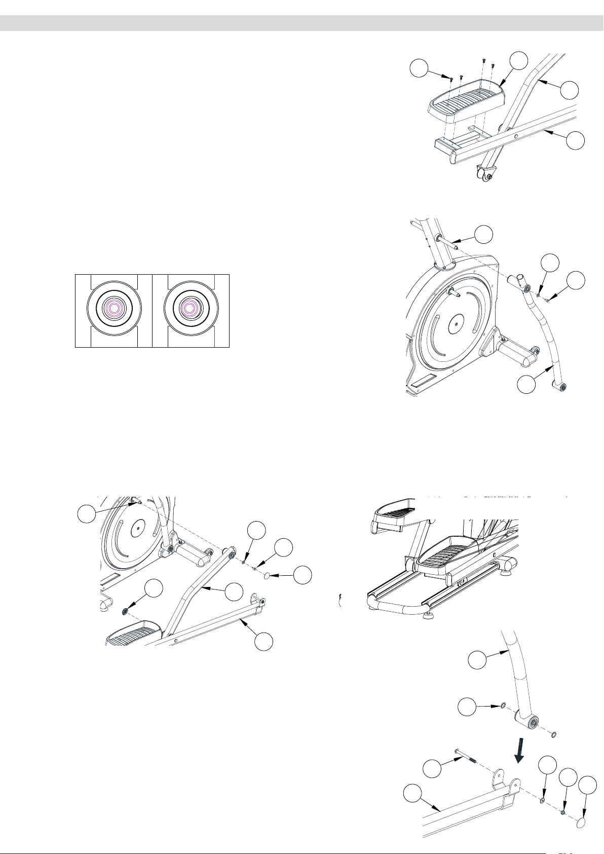
Step 5.1: Assembling the Pedal Arms, Guide Tubes and Pedals
Loosen and remove the four Allen screws (B23) attached to the right pedal
arm (A06). Then x the pedal (C12) to the right pedal arm (A06) using the
four Allen screws (B23) just removed.
Repeat this procedure with the left pedal.
Step 5.2:
Now place the right pendulum tube (A04) onto the previously lubricated right
axle on the handlebar stem (A02). Fix the pendulum tube (A04) with a screw
(4) and a washer (2). Make sure that the washer is in a centralised position
on the axle – see Fig. 1.
NOTE:
We recommend lubricating both transverse axles on the handlebar stem
with a multi-purpose grease before assembling the pendulum tubes. This will
optimise the smooth running of the pendulum tubes.
Fig. 1
B23
C12
A08
A06
4
Right Wrong
Step 5.3:
Slide the front mount on the right guide tube (A08) onto the small axle (A11)
on the right drive disk on the main frame and set the rollers onto the right tracks on the slide frame.
NOTE:
We recommend lubricating the axle (A11) on the drive disk with a multi-purpose grease before assembling the
pedal arm. This will optimise the smooth running of the pedal arm and guide tubes.
Fix the right guide tube (A08) with a hexagonal screw (4) and a washer (2). Now cover up the screw heads (4)
with the round caps (C11).
A11
C11
A08
2
A06
4
C11
A04
Step 5.4:
Loosen and remove the screw (B24), the washer (B33) and the nut (B29) on
the front mount of the pendulum tube (A04). Now connect the pendulum tube
(A04) with the pedal arm (A06) using the screw (B24), the washer (B33) and
the nut (B29) which you just removed.
Make sure that the two washers (C22) on pendulum tube (A04) are sitting
correctly. Then cover the nuts (B29) with the round caps (C11).
Step 5.5:
Repeat the assembly steps described above for the left pendulum tube
(A03), pedal arm (A05) and guide tube (A07).
8
A06
B24
C22
A04
B33
B29
C11
Page 9
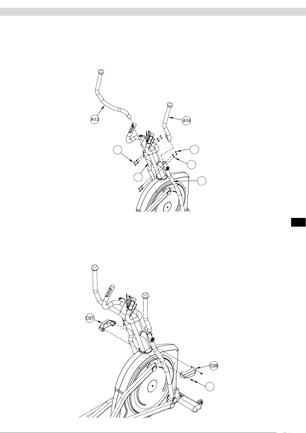
Step 6: Assembling the Pendulum Handlebars
Place the left handlebar (A13) in the mount on the left pendulum tube (A03) and the right handlebar (A14) in the
mount on right pendulum tube (A04).
The right and left handlebars are each labelled and so easy to identify. Fix each of the handlebars with two
carriage bolts M850 (7), two curved washers M8 (6) and two lock nuts M8 (14).
Assembly
7
14
6
A03
Step 7: Assembling the Covers to the Handlebar Stem
Attach the two handlebar-stem covers (C07-left/C08-right) using two tapping screws M5x16 (8) to the joint between the handlebar stem and the main frame.
A04
ENG
8
9
Page 10
Assembly
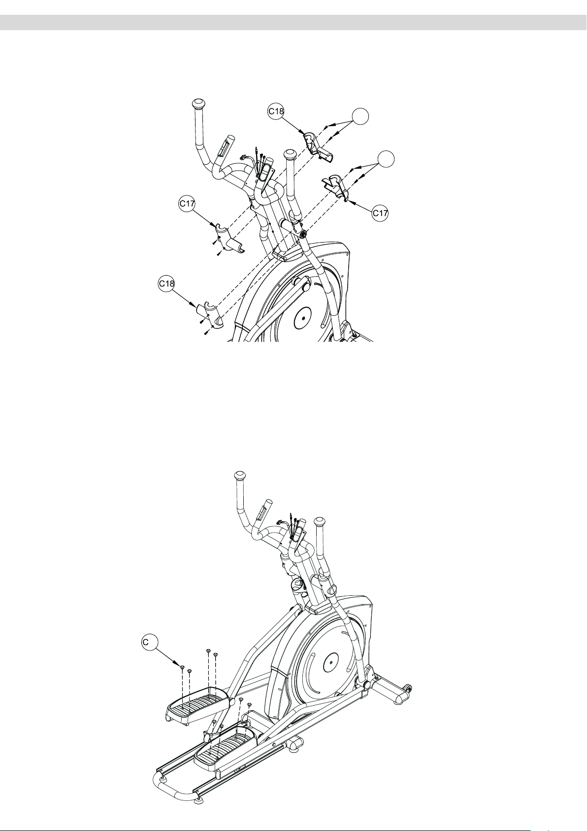
Step 8: Assembling the Pendulum Handlebar Covers
Attach both pendulum handlebar covers (C17/C18), using two tapping screws M5x16 (8) on each,
to the left and right pendulum handlebars (A03-left/A04-right) as shown in the diagram.
8
8
Step 9: Assembling the Pedal Covers
Now press the four covers (C14) into the round holes on the pedal treads.
14
10
Page 11
A
A02
0
16
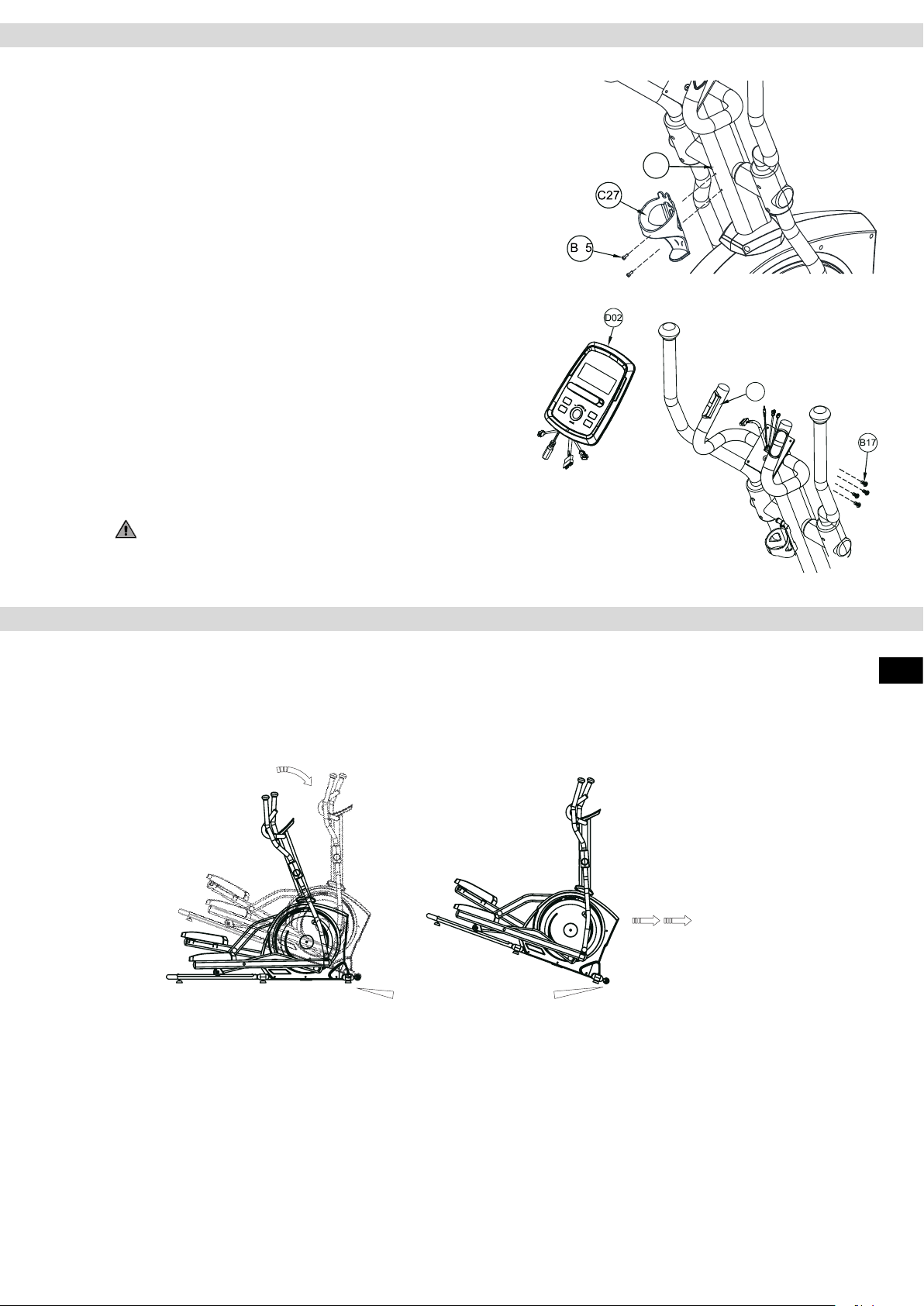
Step 10: Assembling the Bottle Holder
Loosen and remove the two screws M5 (B05) which are preassembled on the handlebar stem (A02). Attach the bottle holder
(C27) to the handlebar stem (A02) with the two screws M5 (B17)
Step 11: Assembling the Cockpit
Loosen and remove the four pan head screws (B17) preassembled on the back of the cockpit. Connect the cables protruding
from the cockpit (D02) with the cables that protrude from the xed
handlebars. Please note that the two cables of the hand pulse
sensors have identical connections. The order of connection is
not important here. The other two cables can be easily identied
by their connections.
Now secure the cockpit (D02) to the cockpit bracket on the xed
handlebars (A16) using the screws (B17).
Assembly
A02
0
16
A
WARNING: Make sure that you do not pinch or damage the
cables during assembly.
Transport, Location and Storage
Transport
In order to transport your training device simply and safely, the front stand is equipped with transport rollers. To
transport the exerciser, stand at the rear end of the glide frame and grasp the rear cross tube with both hands.
Now tip the training device upwards until the main weight of the training device rests on the transport rollers.
Now you can simply push the device on the transport rollers into the required position. Always make sure that
you have a rm and secure footing when lifting, transporting and putting down the device.
ENG
Transport rollers
Safety Distance
Choose training area which allows you free space on all sides and the greatest possible security.
The safety area should always be at least 100 cm to each side, and 100 cm behind and in front of the training
device.
Location and Storage
This training device was designed for use in dry, warm indoor areas. It is not to be used or stored in damp or wet
areas such as saunas, swimming pools, etc. or in outdoor areas, such as balconies, terraces, gardens, garages, etc. Due to the high humidity or low temperatures possible in any of these areas, damage may occur to the
electronics or corrosion and rust defects may arise. No warranty claims for damage of this kind will be accepted.
Please choose a warm, dry, level location for your training equipment both for when in operation and in storage.
For your own comfort, make sure that the training area is suciently ventilated during exercise to allow optimal
oxygenation. Before using your training device after a long period of non-use, make sure that all fastenings are
secure.
11
Page 12
Maintenance and Care
CAUTION
Before starting cleaning, maintenance and / or repair work, the exerciser must be completely disconnected from
the power supply. This will only be the case if the mains cable is disconnected from the power socket and from
the training device. Therefore, rst disconnect the electrical plug from the power socket, and then disconnect the
mains cable from the exerciser. The mains cable may only be reconnected to the training device and the power
supply when all work has been completed and the proper functional condition of the device has been restored.
Cleaning
Clean your training device after each workout. Use a damp cloth and soap. Never use solvents. Regular cleaning contributes signicantly to the preservation and longevity of your training device. Due to the chemical composition of body sweat, this is the main cause of corrosion (rust) if not removed immediately. Therefore, after
every training session, check whether body perspiration and / or other uids have got onto the device. If this is
the case, the aected components / housing parts must be cleaned.
Please note that damages caused by body sweat or any other liquids are not in any way covered by the warranty.
During training, make sure that no uid can enter the training device or the computer.
Maintenance
Checking the fastenings
Check the tightness of nuts and bolts at least once a month and re-tighten if necessary.
Lubricating the sliding tubes
The top of the sliding tubes must be cleaned and lubricated regularly. Clean the sliding tubes with a damp cloth
and some liquid hand soap or detergent. For professional cleaning we recommend the MAXXUS® Degreaser
Spray. Then dry the sliding tubes thoroughly and lubricate the top of the tubes with liquid silicone or MAXXUS®
lubricant spray to form a thin layer.
With frequent use, you should clean and lubricate the sliding tubes once a week. Lubricate the sliding tubes immediately if squeaking sounds occur during training. Care and cleaning agents are available in our online shop
at www.maxxus.com or in our showroom in Weiterstadt.
Lubricating the axles on the handlebar stem and on the drive discs
The two transverse axles on the handlebar stem, and the axles on the large drive discs, should be lubricated
once every 6 months with multipurpose grease - please refer to the appropriate section in this manual.
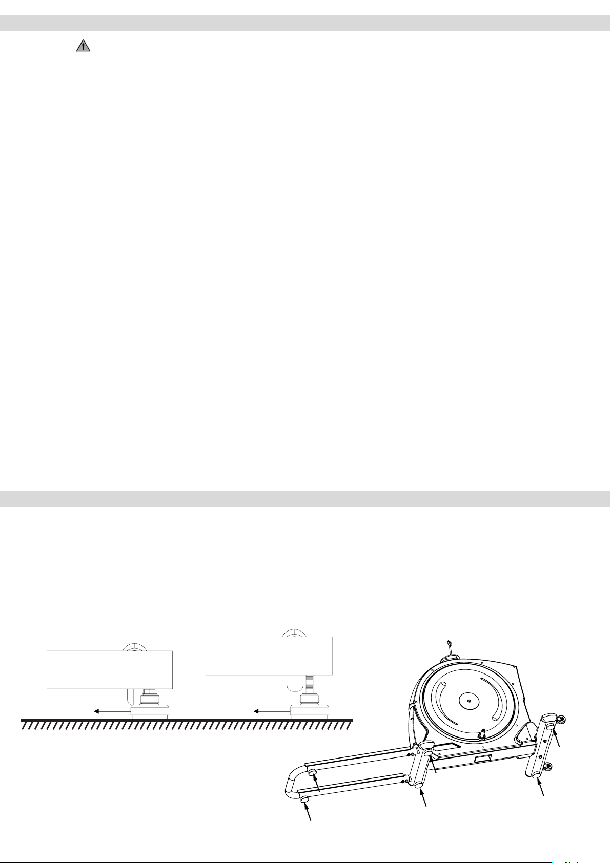
Levelling the Device
Make sure your exercise equipment is always level. In order to compensate for minor bumps or slopes in the
oor, adjustable feet are tted on the right and left of the front and rear stands and on the sliding frame. To make
sure the position of the device is level, rst turn all feet to the lowest position (position A). If necessary, adjust
the feet until the device is level and stable.
If the adjustment range of the levelling feet is not enough to allow the training device to stand safely, please
check the surface of the location and, if necessary, choose a dierent location, where a safe and level position
can be ensured.
Position A
Position B
Adjustable foot Adjustable foot
Adjustable foot
Adjustable foot
12
Page 13
Mains Cable
Mains Cable
Insert the connector of the power cable supplied into the socket located on the rear of the main housing. Then
connect the mains cable to a power socket.
WARNNG
This device is only to be connected to an earthed socket installed by a qualied electrician. Do not use a socket
strip. If an extension cable is required, then it must comply with DIN standards, VDE regulations and guidelines,
technical rules issued by other European Union member states or other states which are party to the Agreement
on the European Economic Area.
Connecting the device
WARNNG
Before connecting the mains adapter to the device, always check that it is the mains adapter supplied with the
device. Using a dierent mains adapter may damage the electronic components of the device, for which the
manufacturer assumes no liability.
Always connect the power cable to the exerciser before connecting it to a power outlet. If you want to discon-
nect your exerciser from the power supply, always disconnect the power cable from the mains rst.
Switching on the device
First connect the power cable to the exerciser and then connect the mains cable to the power socket, the cockpit turns on automatically. If the training device is already connected to the mains, but the cockpit is in stand-by
mode, activate the cockpit by pressing any key or by moving the pedals.
Turning o the device
When inactive for more than 4 minutes, the cockpit automatically switches to stand-by mode. Once you have
nished your workout you should always disconnect the exerciser from the mains. Always unplug the mains
cable from the wall socket rst and then remove the power cable.
ENG
13
Page 14
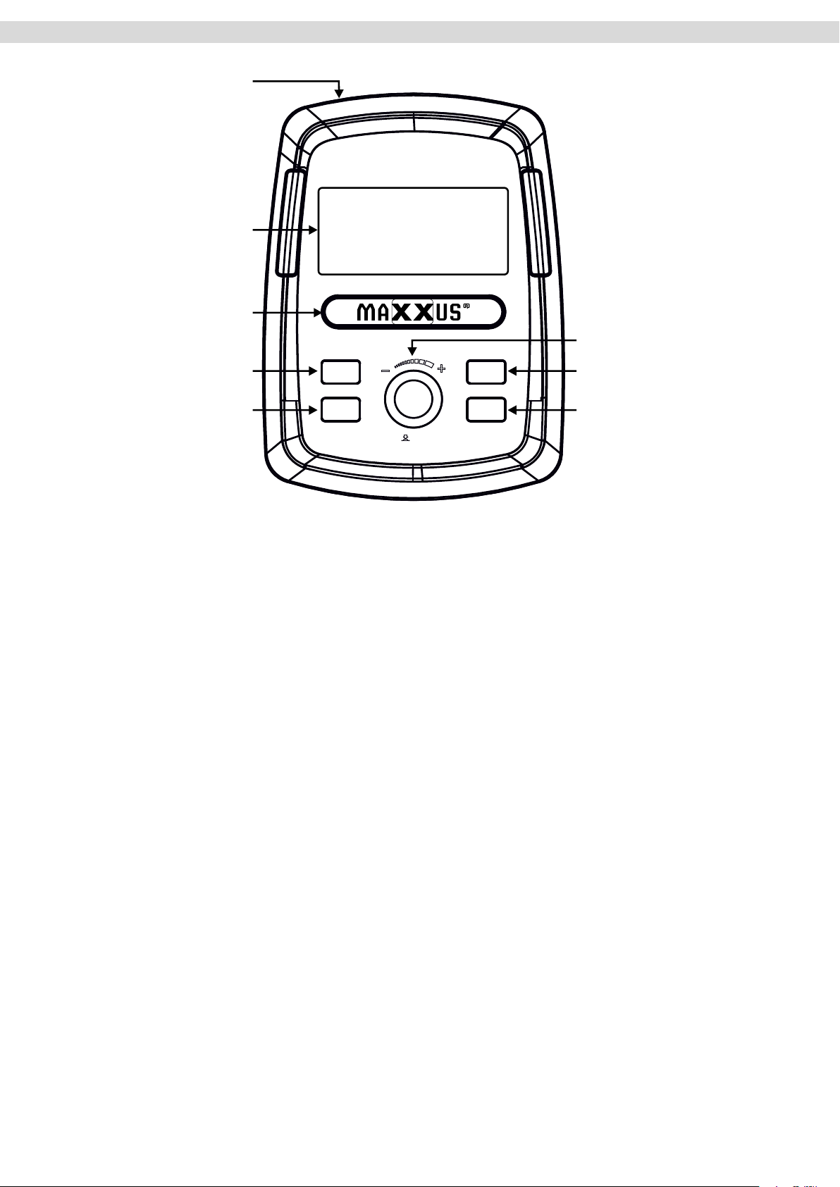
Cockpit
USB port with charging function
LCD display
Storage compartment for
Smartphone, Tablet PC
Control knob
Recovery pulse measurement
Body fat analysis
RECOVERY
BODYFAT
MODE
RESET
START/STOP
RESET key
START / STOP key
The cockpit constantly shows the current training values.
TIME
Specication of the training time. For a given training session, the computer counts down the time to “00:00.” The training time can
be set from “01:00” to “99:00” minutes in one-minute increments. If no time is specied, the computer will count the training time from
„00:00” up to a maximum of „99:00” minutes.
DISTANCE
Specication of the training distance in kilometres. For a given training session, the computer counts down the distance back to “0.00.”
The training distance can be set from 1.0 to 99.0 Kilometres in 1.0 km increments to maximum of 99.0 kilometres. If no training dis-
tance is specied, the computer will count the kilometres from 0.0 to a maximum of 99.0 kilometres.
CALORIES*
Indication of energy consumption in Kcal. For a given calorie consumption, the computer counts the calories down to 0. The calorie
consumption can be set from 10 to 990 K in 10-Kcalorie increments. If the calorie consumption is not specied, the computer counts
the K-calories from 0 to a maximum of 990 K-calories
Pulse or heart rate display - PULSE
When using the hand pulse sensors displays the current pulse value in beats per minute. When using an optional transmitter chest belt
(not included) displays the current heart rate in beats / minute.
SPEED
Current speed in km / h. Value is displayed alternately with RPM in the same window.
Revolutions per minute - RPM
Specication of the current wheel revolution per minute (RPM). Value is displayed alternately with SPEED in the same window.
Resistance - LEVEL
Display of the currently selected resistance level from 1 to 16.
Power - WATT**
Display of the power output in Watts.
* Warning about the calorie measurement
Energy consumption is calculated by means of a general formula. It is not possible to determine the exact energy consumption individually as this requires a large amount of
personal data. The energy consumption displayed is approximate and not an exact value.
**Warning about the Watt display
Since this is a training device suitable for non-therapeutic purposes, the displayed value in Watts is not a calibrated value. The displayed power generated may dier from the
actual power generated.
14
Page 15
Keypad
START/STOP Key
START Function: – Start the selected training program or training prole
– Activate the QUICK START function
PAUSE Function: If the START / STOP key is pressed during training, the display of training values stops,
and the pause mode is activated. This allows an interruption of training.
To end the pause, press the START / STOP key again.
RESET Key
If the key is pressed constantly for more than 5 seconds, all values are automatically reset to zero.
To change the user, exit the current program by pressing the START / STOP key. Then press the RESET until
the display switches on again.
Control Knob
Turning Function: – Specication of training values
– Input of date (eg age)
– Regulating the resistance level
Pressing Function: – Conrmation of inputs
RECOVERY
Key to start the recovery pulse measurement.
Cockpit
Body Fat Measurement - FAT
Key to start the body fat measurement.
User Settings
After the cockpit has been switched on, the display shows “U1”. There are four user proles available U1 ~ U4.
These are xed, i.e. the user data is stored permanently.
Selecting a User Prole
Turn the control knob to select the desired user prole and conrm your selection by pressing it.
Gender Input
Turn the control knob to select your gender and conrm your selection by pressing it.
Age Input
Enter your age by turning the control knob and conrm your entry by pressing it.
Height Input
Enter your height by turning the control knob and conrm your entry by pressing it.
Weight Input
Enter your body weight by turning the control knob and conrm your entry by pressing it. After you have conrmed the input of body weight the display automatically changes to the training menu.
If you have already created a user prole, select this as soon as you have switched on the cockpit by turning the
control knob. Then the information for gender, age, height and body weight will be checked. If the details are still
correct, conrm them by pressing the control knob. If some inputs have changed, correct them accordingly and
conrm by pressing the control knob
ENG
15
Page 16
Cockpit
Quick-Start
Turn on the training device and press the START / STOP key. The training time will start to run, and you can
start training. At any time during training, you can adjust the resistance level from 1 to 16 by turning the control
knob clockwise / anti-clockwise. Since no target value can be specied in this type of training, you must end the
training yourself.
Manual Training - MANUAL
Step 1: Program Selection
Turn on the exerciser. An “M” will ash in the upper part of the display. If a dierent symbol is ashing, select “M”
by turning the control knob clockwise / anti-clockwise. Conrm your selection by pressing the control knob.
Step 2: Program Selection Resistance Level
The value in the “LEVEL” window will ash. Set the desired resistance level from 1 to 16 by turning the control
knob clockwise / anti-clockwise. This can be changed individually during training at any time. Conrm your
selection by pressing the control knob.
Step 3: Specication of the Target Values
You now have the choice of three dierent goals:
Training Time (“TIME”):
The value in the “TIME” window ashes. If you want to specify the training time, enter it by turning the control
knob clockwise /anti-clockwise. You can set the exercise time from 1:00 to 99:00 minutes in 1-minute increments. Conrm your selection by pressing the control knob.
If you do not want to specify the training time, press the control knob directly to conrm. The value in the “TIME”
window should show “00:00”.
Training Distance (“DISTANCE”):
The value in the “DISTANCE” window ashes. If you want to specify the training distance, enter it by turning the
control knob clockwise / anticlockwise. You can set the training distance from 1.0 to 99.0 kilometres in 1-kilometre increments. Conrm your selection by pressing the control knob. If you do not want to specify the training
distance, press the control knob directly to conrm. The value in the “DISTANCE” window should show “0.00”.
Calorie Consumption (“CALORIES”):
The value in the “CALORIES” window ashes. If you want to specify the calorie consumption, enter it by turning
the control knob clockwise / anticlockwise. You can set calorie consumption from 10 to 990 K-calories in 10
K-calorie increments. Conrm your selection by pressing the control knob.
If you do not want to specify the calorie consumption, press the control knob directly to conrm. The value in the
“CALORIES” window should show “0”.
Note:
It does not make sense to specify more than one training goal per training session. If you do, training will stop
after reaching the rst target value.
Step 4: Specifying the Pulse Upper Limit
The value in the “PULSE” window ashes. You can now set a pulse upper limit of 30 to 230 heartbeats / minute
by turning the control knob clockwise / anticlockwise. If your actual heart rate reaches this level during exercise,
a warning will sound. If you do not want to set a pulse upper limit, press the control knob directly to conrm. The
value in the PULSE “window should show “ 0 “.
Step 5: Training Start
Press the START / STOP key to start exercising.
End Training
After the predetermined training goal has been reached, training will end automatically
Controlling the Resistance Level
During exercise, you can change the currently selected brake level at any time by turning the control knob clock-
wise / anticlockwise.
16
Page 17
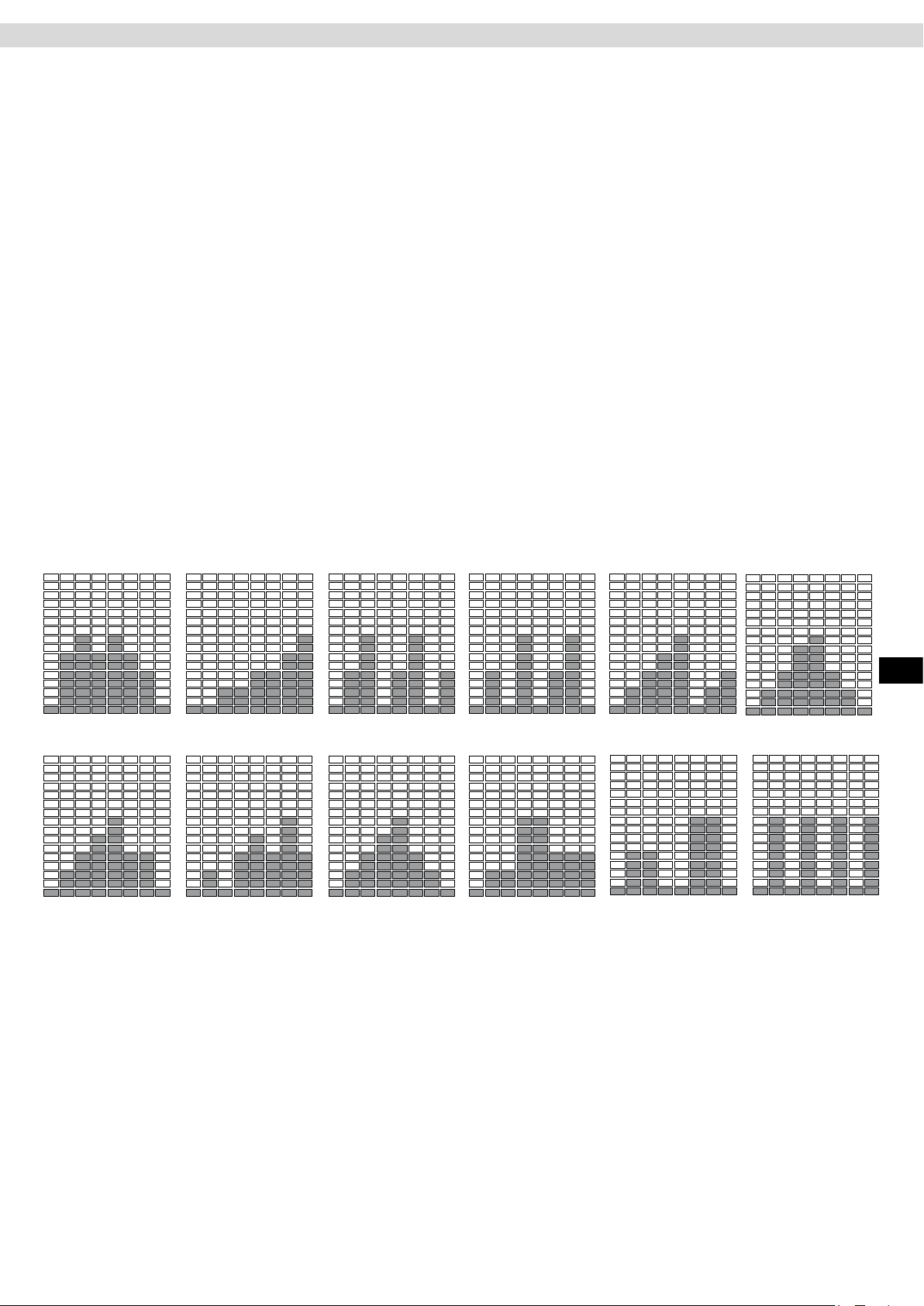
Training Proles P1 – P12
In this type of training, the user can choose from twelve pre-programmed training proles. The prole is not
changeable; however, the user has the option of adjusting the intensity of the respective prole according to
their current state of tness.
Step 1: Program Selection
Turn on the exerciser. The upper part of the display ashes “M”. Select the desired training prole by turning the
control knob clockwise / anti-clockwise.
Step 2: Setting the Training Level
Select the desired training level by turning the control knob clockwise / anti-clockwise. Conrm your selection by
pressing the control knob.
Step 3: Setting the Training Time
The value in the “TIME” window ashes. Enter the training time by turning the control knob clockwise / anticlockwise. You can set the exercise time from 1:00 to 99:00 minutes in 1-minute increments.
Step 4: Training Start
Press the START / STOP key to start exercising.
Training End
When the desired training time has been reached, training will end automatically.
Setting the Training Level
During training, you can change the currently selected training level within the given frame by turning control
knob clockwise / anti-clockwise at any time.
Cockpit
P1
P7
P2
P8
P3
P9
P4
P10
P5
P11
P6
ENG
P12
17
Page 18
Cockpit
Free Training Prole (USER)
Here you can create a training prole per user prole yourself and save it permanently.
Step 1: Selecting a Program
Turn on the exerciser. The upper part of the display ashes “M”. Select the program “U” by turning the control
knob clockwise / anti-clockwise and conrm your selection by pressing it.
Step 2: Programming the Training Segments
The rst of a total of eight training segments will ash in the display. Set the desired resistance level from 1 –
16 for the rst training segment by turning control knob clockwise / anti-clockwise and conrm your entry by
pressing it. Now the second segment ashes. Repeat this procedure with this segment and all the way through
to segment 8. After you have conrmed the input for the 8th segment by pressing the control knob, this training
prole will be permanently stored.
Step 3: Setting the Training Time
When the rst segment ashes again. Press the control knob until the value in the “TIME” window ashes. Then
enter the exercise time by turning the control knob clockwise / anti-clockwise. You can set the exercise time
from 1:00 to 99:00 minutes in 1-minute increments.
Step 4: Training Start
Press the START / STOP key to start exercising.
Training End
After the training time has expired, the training will end automatically.
NOTE:
If you want to change the saved training program, switch on the cockpit. Select the program “U” by turning the
dial clockwise / anti-clockwise and conrm your selection by pressing it. Now the rst segment ashes again.
Press the control knob until the value in the “TIME” window ashes. Enter the exercise time by turning the dial
clockwise / anti-clockwise.
You can set the exercise time from 1:00 to 99:00 minutes in 1-minute increments. Now press the START / STOP
key to start training.
Heart Rate Controlled Programs (HRC)
These programs are heart-rate-controlled exercise programs. The user species a desired target heart rate.
This is permanently compared by the cockpit with the actual heart rate of the user. If the actual heart rate is
lower than the desired target heart rate, the cockpit automatically increases the resistance. If the value is higher,
the cockpit automatically reduces the resistance.
The main requirement for these programs is a permanent and accurate transmission of heart rate values. For
this reason, these programs can only be used together with an uncoded heart rate chest belt which is available
as an extra accessory. It is not possible to use these programs with hand-pulse sensors. Please also read the
chapter “Heart rate measurement” in this manual.
Step 1: Selecting a Program
Turn on the exerciser. The upper part of the display ashes “M”. Select the heart symbol by turning the control
knob clockwise / anti-clockwise and conrm your selection by pressing it.
Step 2: Age Input
The display will show the letter “A” and the value “25” will ash, enter your age from 1 to 99 years by turning the
control knob clockwise / anticlockwise, and conrm your entry by pressing it.
Step 3: Selecting the HRC Mode
By pressing the UP & DOWN keys, you can now choose between the following HRC modes:
50% – Training with a target heart rate of 50% of the maximum heart rate
75% – Training with a target heart rate of 75% of the maximum heart rate
90% – Training with a target heart rate of 90% of the maximum heart rate
TA – Training with an individual target heart rate
Please also read the section “Warning for Pulse & Heart Rate Measurement” in this manual.
Select the desired modes by turning the control knob clockwise / anti-clockwise.
If you select 55%, 75% or 90%, the corresponding target heart rate will be displayed directly. Conrm your
selection by pressing the control knob.
To train with an individual target heart rate, select the TA mode by turning the control knob clockwise / anti-clockwise and conrm the selection by pressing it. The “PULSE” window will ash “100.” Now enter the desired target
heart rate between 30 and 230 heartbeats / minute again by turning the control knob clockwise / anticlockwise
and conrm your entry by pressing it.
18
Page 19
Step 4: Setting the Training Time
The value in the “TIME” window ashes. Enter the training time by turning the control knob clockwise / anti-clockwise. You can set the exercise time from 1:00 to 99:00 minutes in 1-minute increments.
Step 5: Training Start
Press the START / STOP key to start exercising.
Training End
After the training time has expired, the training is automatically ended.
Program Procedure
The cockpit determines the current heart rate of the user and compares it continually with the desired target
heart rate. If the current heart rate is lower or higher than the target heart rate, the cockpit automatically increases or decreases the resistance level.
If the current heart rate is within +/- 5 beats / minute below or above the target heart rate, the cockpit will maintain the current resistance level.
If the cockpit cannot determine the user’s heart rate, the display shows “?”. In this case, check the correct
position and battery power of the chest belt and make sure that it is an uncoded belt with the 5 kHz transmission
frequency.
Example:
Target heart rate is 120 - no change in the brake level at a current heart rate of 115 ~ 125 beats / minute.
Watt-controlled training programs (WATT)
In this type of training the power in watts selected by the user is kept constant permanently by the cockpit. The
user’s output (watts) results from the current resistance level and the current pedalling speed. To keep the power constant, the cockpit reduces the resistance level as soon as the user increases the pedalling speed. If the
user reduces the pedalling speed, the cockpit automatically increases the resistance level. This is also called
speed-independent training
Cockpit
The user has three xed watt-training proles and a watt-constant program to choose from.
Step 1: Selecting a Program
Turn on the exerciser. An “M” will ash in the upper part of the display. Select the program “W” by turning the
control knob clockwise / anticlockwise and conrm your selection by pressing it.
Step 2: Setting Watt Value
The value in the “WATT” window ashes. Enter the desired wattage by turning the dial clockwise / anti-clockwise. Inputs from 10 to 350 watts in 5-watt increments are possible. Conrm your entry by pressing the control
knob.
Step 3: Setting the Training Time
The value in the “TIME” window ashes. Enter the desired training time by turning the control knob clockwise /
anti-clockwise and conrm your entry by pressing it.
Step 4: Training Start
Press the START / STOP key to start exercising.
Training End
After the training time has expired, training will end automatically.
ENG
19
Page 20
Cockpit
Recovery Heart Rate (RECOVERY)
The recovery test measures how quickly you recover, i.e. how quickly and by how much your heart rate decreases after training.
After completing a workout, or after stopping the workout by pressing the Stop key, press the RECOVERY key
and immediately place your hands on the hand pulse sensors. If you are wearing a chest strap, you do not need
to hold on to the hand pulse sensors. Now the cockpit will try to determine your pulse for 10 seconds. If this
fails, the test is automatically terminated.
If the cockpit has detected your pulse, a countdown of 60 seconds starts in which you must keep hold of the
hand pulse sensors all the time (this is also not necessary if you are wearing a chest strap).
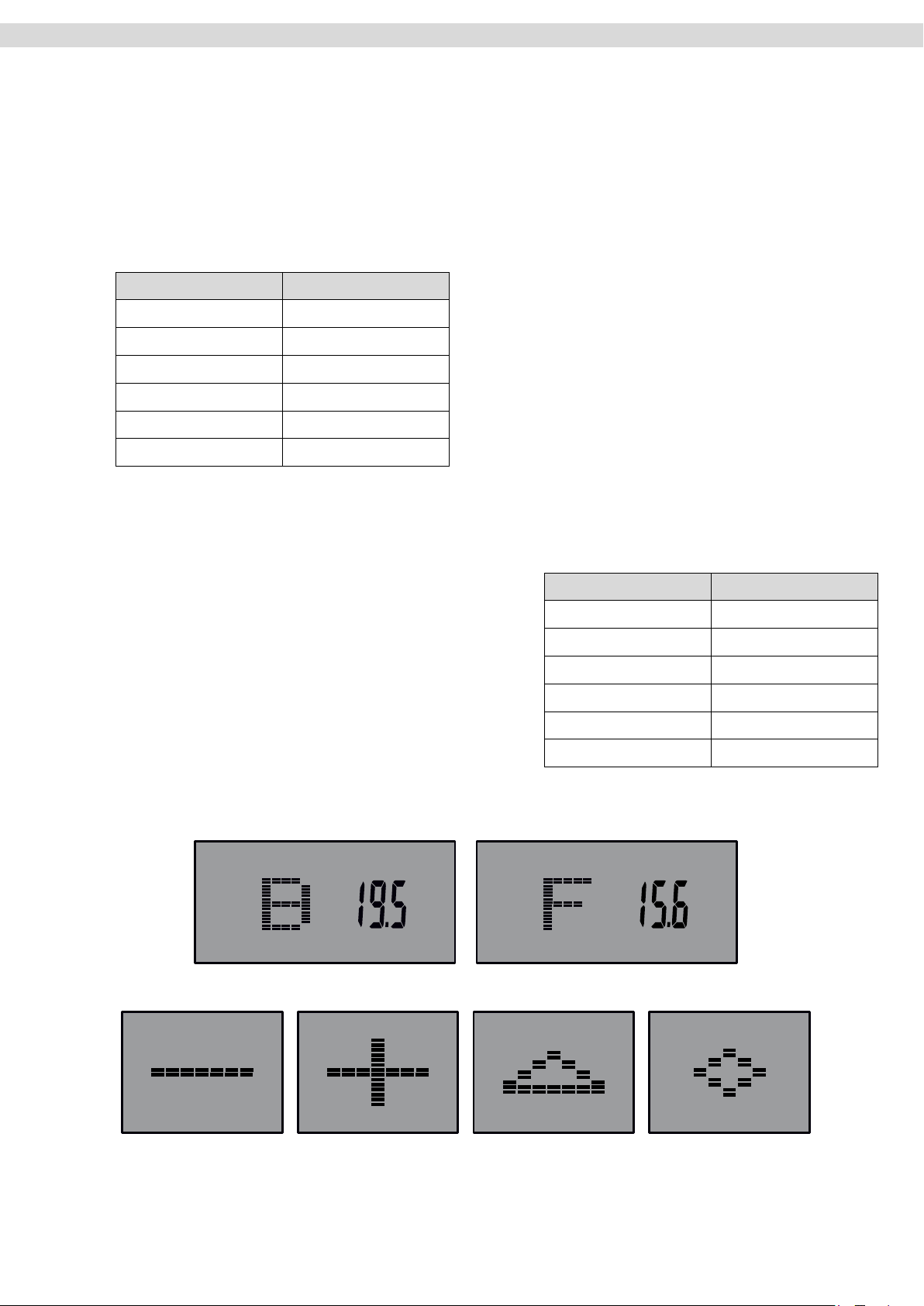
After the 60 seconds have elapsed, you can read the result on the display and compare it with the following
table.
Result Evaluation
F1 Excellent
F2 Very good
F3 Good
F4 Satisfactory
F5 Sucient
F5 Poor
Body Fat Analysis (Body Fat)
This program determines the percentage of body fat and the BMI of the user.
Press the FAT key. The currently selected user prole is displayed as “U1”. If the wrong user prole has been selected, press
the RESET key and select the correct user prole. Then press
the FAT key again and grasp the hand pulse sensors with your
hands. After successful measurement, the percentage of body fat
is displayed with the corresponding symbol and BMI.
Body-Mass-Index (BMI)
This value is calculated from the ratio of body weight to height
and is used to assess the body weight of a person in relation to
their height. Please note that the BMI is only a rough guideline,
as it does not account for physique and gender or the individual
composition of the body mass of fat and muscle tissue. The “ideal” BMI depends on the age.
BMI Body fat percentage %
Age BMI
19 - 24 years 19 - 24
25 - 34 years 20 - 25
35 - 44 years 21 - 26
45 - 54 years 22 - 27
55 - 64 years 23 - 28
> 64 years 24 - 29
Symbols representing the body fat percentage
Low Normal Raised High
USB Charging Function
The cockpit has a USB connection located at the top of the cockpit. This connection is to be used only for charging of smartphones or tablet-PC’s during training. The cable required for this is not included in delivery.
20
Page 21
Bluetooth Receiver and APP Usage
The cockpit of your training device comes ready tted with an integrated Bluetooth receiver. This Bluetooth
receiver allows the tness device to be controlled from your smartphone or table PC via an App.
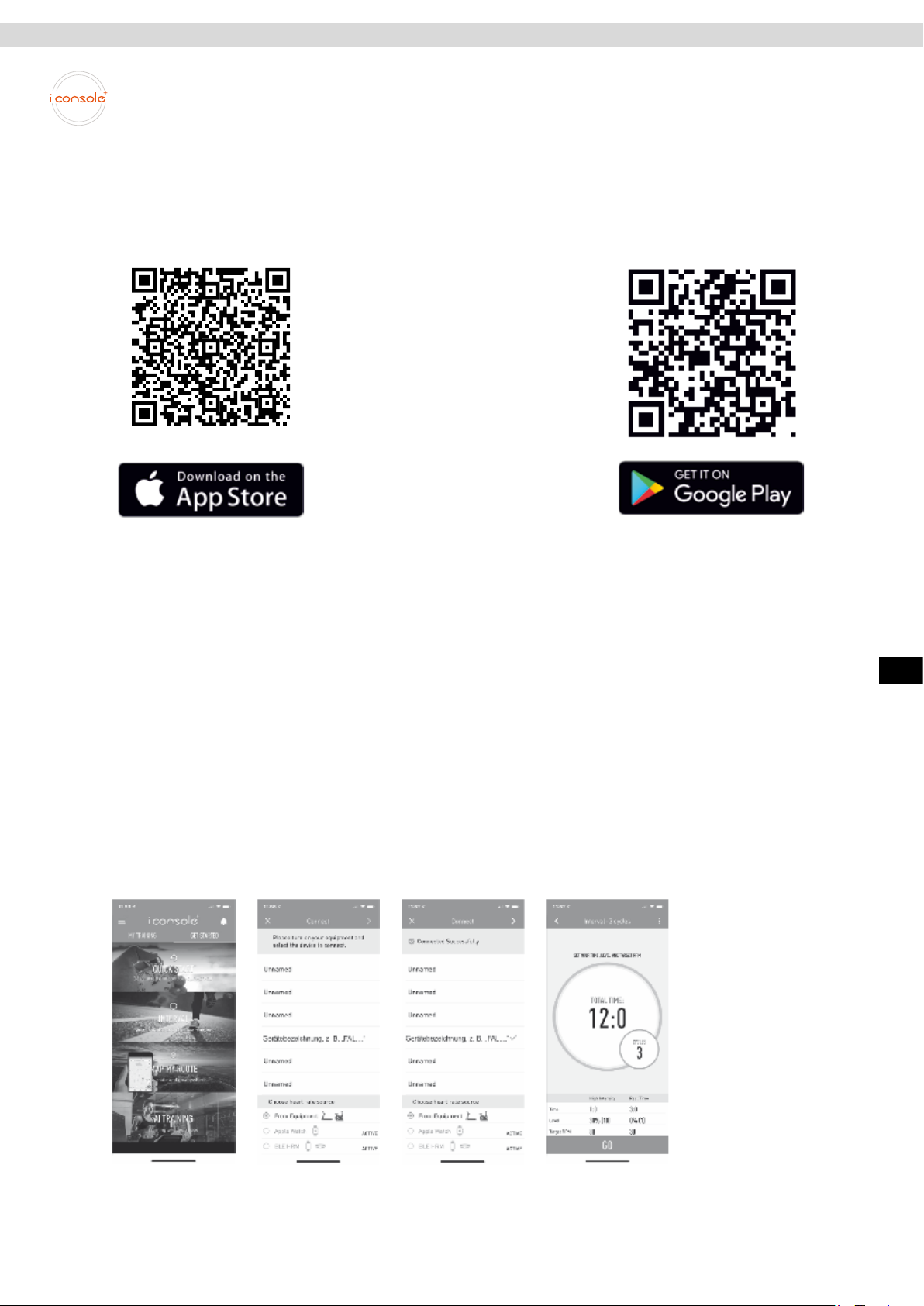
Connect the iC+ Training-App with your training device as follows:
Step 1
Download the iC+ Training-App from the appropriate Store onto your smartphone or tablet PC.
For requirements of compatible devices
and required software versions, please
refer to the appropriate store page.
* Note: If the links are no longer valid, please enter
“iC + Training” or “iConsole +” in the search bar of the
relevant store.
The logo to search for for the “iConsole+” APP has
orange writing on a white background.
Cockpit
Step 2
Activate the Bluetooth function on your smartphone or tablet PC
Open the iC+ Training App
Step 3
Select “GET STARTED” in the top right of the menu. Then select the required training type, such as “QUICK
START”
Step 4
A list of available Bluetooth devices will appear on the display of your smartphone or tablet PC. Make sure your
training device is switched on. Select your training device from the list. The name of the training device starts
with “FAL ...” or “MAXXUS”. After successful connection, a tick symbol will appear. Your training device will now
be stored by the iC + Training App so you can start training straight away the next time you want to train.
Step 5
After successfully pairing the App with your training device, you can continue training by clicking on the arrow in
the top right corner of the display.
ENG
Please note that the MAXXUS Group GmbH & Co. KG is not the manufacturer of the iC + Training App and
therefore are not responsible for their content or features.
21
Page 22
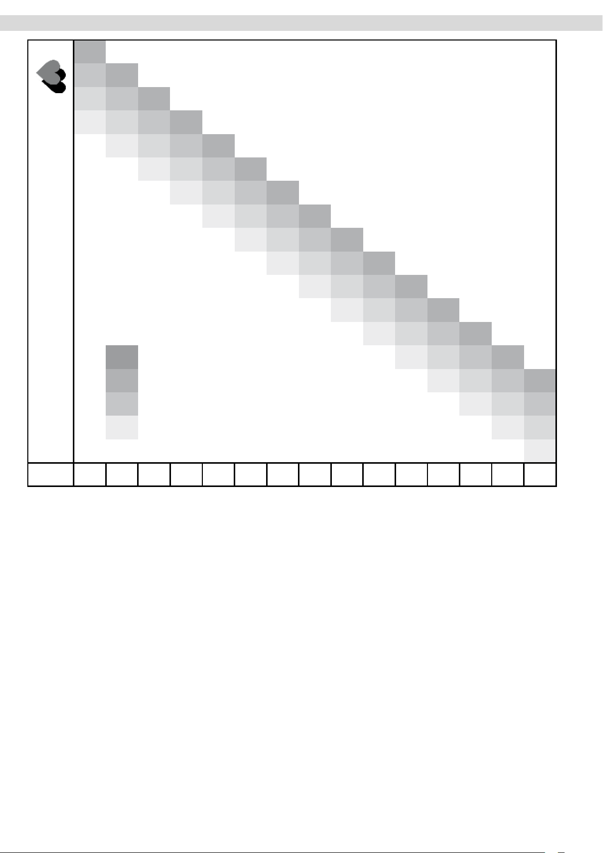
Pulse & Heart Rate
200
150 195
Heart Rate per Minute
130 146 190
110 127 143 185
107 124 139 180
105 120 135 175
102 117 131 170
99 114 128 165
96 111 124 160
100%
of maximum heart rate
75%
of maximum heart rate
94 107 120 155
91 104 11 6 150
88 101 11 3 145
85 98 109 140
83 94 105 135
80 91 101 100
65%
of maximum heart rate
55%
of maximum heart rate
77 88 98
74 85
72
Age
Calculating your personal heart rate when training
Calculate your personal heart rate when training as follows:
220 - Age = maximum heart rate
This value represents your maximum heart rate and serves as a basis from which to calculate
your personal training heart rate. Set the calculated heart rate at 100%
Wellness and Health - target zones = 50 to 60% of the maximum heart rate.
This training zone is ideally suitable for people who are over-weight and/or older beginners, or people starting again after a longer
break from training. Training in this zone the body will burn approx. 4-6 calories per minute to produce energy.
The percentage ratio per calorie is approx. 70% fat, 25% carbohydrate, and 5% protein.
Fat burning - target zone = 60 to 70% of the maximum heart rate
This training zone is suitable for athletes and sports people who aim to lose weight.
Training in this zone the body will burn approx. 6-10 calories per minute to produce energy.
The percentage rate per calorie is approx. 85% fat,10% carbohydrate, and 5% protein.
Condition & Fitness - target zone = 70 to 80% of maximum heart rate
This training zone is ideally suitable for athletes and sports people who aim to improve their stamina and/or condition.
Training in this zone the body will burn approx. 10-12 calories per minute to produce energy.
The percentage rate per calorie is approx. 35% fat,60% carbohydrate, and 5% protein.
20 25 30 35 40 45 50 55 60 65 70 75 80 85 90
For optimum eects in training results you should calculate the average value of the selected target zone (also see above table):
Wellness & Health - target zone average value = 55% of maximum heart rate
Fat burning - target zone average value = 65% of maximum heart rate
Kondition & Fitness - target zone average value = 75% of maximum heart rate
22
Page 23
Pulse & Heart Rate
Warning about Pulse and Heart Rate Monitoring
CAUTION: Pulse and heart rate monitoring systems may be inaccurate. Excessive training can cause serious
injury or even death. If you feel unwell and / or faint, stop training immediately. Make sure all users of your exercise device are familiar with this information, understand it and apply it unconditionally.
Pulse Rate Monitoring using Hand Sensors
Most exercise equipment is equipped with hand pulse sensors. These are mostly in the cockpit or integrated into
the handrails. These hand sensors are used for short-term determination of the pulse rate. To do this, you need
to cover the sensors with both hands at the same time. After a short while, the display shows the current pulse
rate. This measuring system is based changes in electrical skin resistance measured by the hand sensors due
to the heartbeat which causes blood pressure uctuations. These changes are summarized to a mean value
and shown in the display as the current pulse rate.
CAUTION.
For large parts of the population, the pulse-induced skin resistance change is so minimal that usable values
cannot be derived from the measurement results. Also callouses on the palms, damp hands and body shakes,
which in many forms of exercise inevitable, prevents correct measurement. In such cases, the pulse value is
displayed incorrectly or not at all.
Please check in the case of a faulty or failed measurement, whether this occurs only with one or with several
people. If the display of the pulse does not work only in individual cases, the device is not defective. In this case
we recommend the use of a chest belt to achieve a permanently correct pulse display. This is available as an
accessory
Heart Rate Measurement using a Chest Belt
Many MAXXUS® training devices are already tted with a receiver as standard.
Using a chest belt (we recommend the exclusive use of an uncoded POLAR® chest strap) allows you to wire-
lessly measure heart rate. The chest belt is as accessories available.
This optimal, ECG-accurate type of measurement takes the heart rate by means of a transmitter chest belt
directly from the skin.
The chest belt then sends the pulse via an electromagnetic eld to the built-in cockpit receiver.
We recommend you always use of a chest belt for heart rate measurement during heart rate-controlled programs.
CAUTION
The determination of the current heart rate by means of the chest belt serves only to display the current heart
rate during exercise. This value says nothing about the safety and eectiveness of the training. Also, this type of
measurement is in no way designed or suitable for medical diagnostic purposes.
Therefore, discuss with your family doctor the most suitable procedure for you and create your exercise plan
before you start exercising.
This applies especially to those who:
− have not been physically active for a long period of time
− are overweight
− are older than 35 years
− have too high or too low blood pressure
− have heart problems
ENG
If you are wearing a pacemaker or similar device, discuss this with your medical specialist before using a heart
rate chest belt.
23
Page 24
Training Recommendations
Preparation Before Training
Before you start training make sure that not only your training device is in perfect condition, your body must also
be prepared for training. Therefore, if you have not done any endurance training for some time, you should con-
sult your GP and undergo a tness check-up. Also discuss your training target; they will certainly be able to give
you valuable advice and information. This applies to people who are over 35, have problems with overweight,
heart or circulatory system problems.
Training Plan
Essential to eective, target orientated, and motivating training is to have a forward-looking trainings plan.
Plan your tness training as an integral part of your daily routine. If you don’t have a xed plan, training can
easily interfere with regular commitments or continually be put o to another unspecied time.
If possible, create a long term monthly plan and not just from day to day or week to week. A training plan should
also include sucient motivation and distraction during training sessions. An ideal distraction is to watch TV
during training as this diverts your attention both visually and acoustically. Make sure that you reward yourself
and set realistic targets such as to losing 1 or 2kgs in four weeks or to increase your training time by 10 minutes
within two weeks for example. If you reach your targets, then reward yourself with a favourite meal which you
have not allowed yourself till then.
Warm-Up Before Training
Warm-up on your training device for 3-5 minutes at minimum resistance. This will best prepare your body for the
up-coming exertion in training.
Cool-Down After Training
Do not just get o your training device immediately the training session is nished. Like with the warm-up stage
you should continue for 3-5 minutes at minimum resistance to cool down. After training you should stretch your
muscles thoroughly.
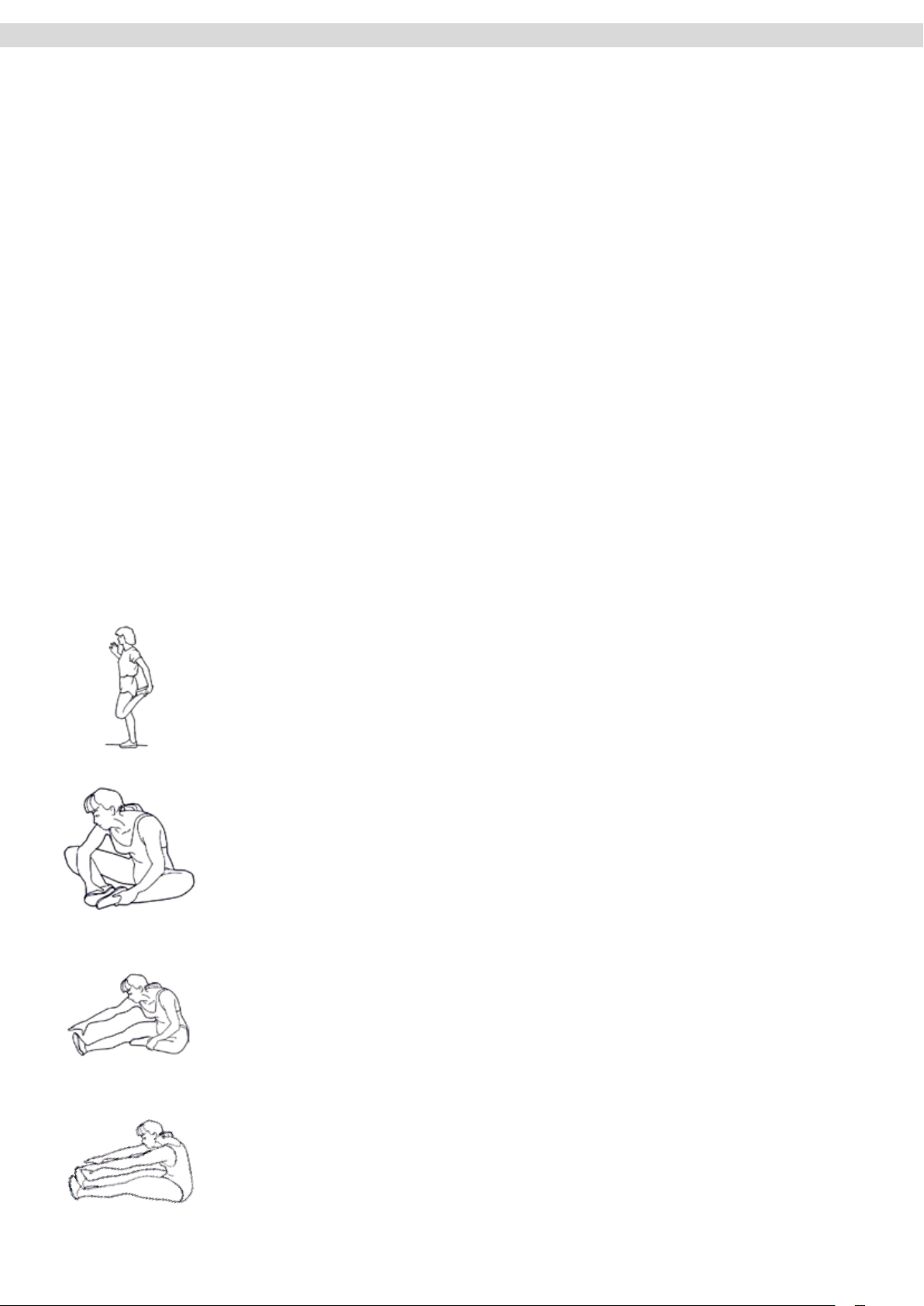
Front Thigh Muscles
Support yourself with your right hand against the wall or on your training device. Bend
your knee and raise your left foot backwards so you can hold it with your left hand. Your
knee should be pointing straight down to the oor. Pull your leg backwards until you feel
a light pulling in your thigh muscles. Hold this position for 10 to 15 seconds. Let your foot
go and stand it back on the oor. Repeat the exercise with your right leg.
Inner Thigh Muscles
Sit on the oor. Pull the soles of your feet together in front of you raising your knees
slightly. Grasp the upper sides of your feet and place your elbows on your thighs. Press
your thighs down towards the oor with your arms until you feel a light pulling in your
thigh muscles. Hold this position for 10 to 15 seconds. Make sure to keep your upper
body straight throughout the exercise. Release the pressure from your thighs and slowly
stretch out your legs to the front. Stand up slowly steadily.
Legs, Calves and Buttocks
Sit on the oor. Stretch out your right leg and bend your left leg to place the sole of your
foot on your right thigh. Bend your top body over so you can stretch out your right hand
to touch your right toes. Hold this position for 10 to 15 seconds. Let go of your toes and
sit slowly and steadily up straight again. Repeat this exercise with your left leg.
Leg and Lower Back Muscles
Sit on the oor with your legs stretched out. Stretch forward with your hands and try to
grasp the tips of your toes with both hands. Hold this position for 10 to 15 seconds. Let
go of your toes and slowly and steadily sit back up straight again.
24
Page 25
Training Recommendations
Hydration
Adequate hydration is essential before and during exercise. During a training session of 30 minutes it is possible
to lose up to 1 litre of liquid. To compensate for this uid loss apple spritzer mixed in the ratio of one-third apple
juice to two-thirds mineral water is ideal since it contains electrolytes and minerals to replace those that the body
loses through sweat. You should drink about 330 ml 30 minutes before the beginning of your training session.
Take care to maintain balanced hydration during the workout.
Training Frequency
Experts recommend that you do endurance training 3-4 days a week to keep the cardiovascular system t. Of
course, the more you train, the faster you will achieve your set training goal. Note however,that you should plan
sucient training breaks during your workout plan, to give your body enough time for rest and regeneration.
After each training session you should take at least one day o. Also for that tness and endurance training:
Less is more!
Exercise Intensity
In addition to the mistake of exercising too often, mistakes are made in the intensity of the training. If your
training goal is to train for a triathlon or marathon, your training intensity will certainly be be high. But since most
people have training goals such as weight reduction, cardiac / exercise training, improvement of physical condition, stress reduction, etc.to strive for, training intensity to meet these goals should be be adjusted. It makes
most sense to work with the appropriate heart rate for the respective training goal. The information on the heart
rate and the corresponding table in this manual will help you further.
Duration of the individual training session
For optimal endurance or weight reduction training, the duration of the individual training session should be between 25 and 60 minutes. Beginners and returnees should start with a low training period of 10 minutes or less
in the rst week and then slowly increase week by week.
Training Documentation
In order to design and evaluate your training eectively, you should prepare yourself a training plan in written
form or as a computer table before starting your training
Here you should document training session. Data, such as distance, training time, brake force setting and pulse
values should be recorded as well as personal data, e.g. body weight, blood pressure, resting heart rate (measured morning immediately after waking up) and personal well-being during exercise.
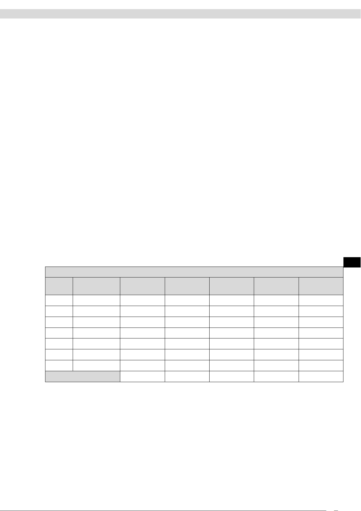
Enclosed you will nd a recommendation for a weekly plan.
Calendar Week:_____ Year: 20____
Date Day
Monday
Tuesday
Wednesday
Thursday
Friday
Saturday
Sunday
Week Result:
Exercise
duration
Exercise
distance
Calorie consumption Ø Heart rate Comments
ENG
25
Page 26
Technical Details
Cockpit
Display of:
− Time
− Distance
− Calorie Consumption
− Power – WATT
− Resistance – Level
Technical details:
Braking system: Motor-controlled permanent magnet brake system
Resistance level adjustment: Computer controlled
Resistance levels: 1 to 16
Flywheel weight: approx. 9 kg
Flywheel Mass: approx. 24 kg
Drive Type: two-stage longitudinal ribbed belt
Stride Length: 53 cm
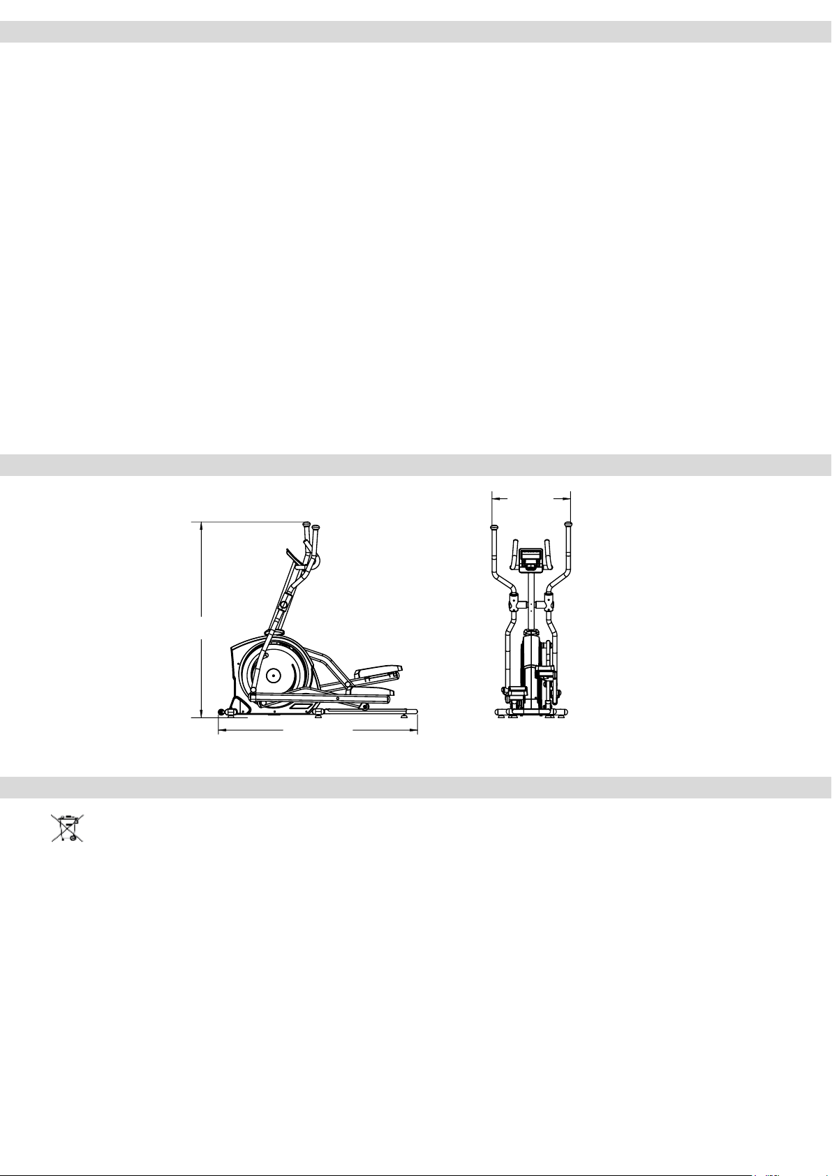
Dimensions: approx. 1,729.5 x 670 x 1,700 mm (LxWxH)
Total weight: approx. 77 kg
Maximum user weight: 160 kg
Mains Adapter: 9V/1.000mA
Power supply: 220-230V - 50Hz
Application: Home use
Dimensions
− Speed
− Wheel revolutions per Minute – RPM
− Pulse Rate (when using the hand sensors)
− Heart Rate (when using an optional chest belt)
670 mm
Disposal
1.700 mm
1.729,5 mm
European Disposal Regulations 2012/19/EU
Do not dispose your training device in the normal household rubbish.
Dispose the device at a communal waste disposal facility or at a registered waste disposal company.
Observe current regulations which apply accordingly. If in doubt seek advice from your local government oce
or county council as to where you can dispose of the device properly and in an environmentally sound manner.
Batteries / Rechargeable Batteries (if applicable to your device)
Batteries and rechargeable batteries should never be disposed of in the household rubbish.
Please be aware that all batteries can contain toxic substances and all consumers are obliged by law to dispose
these at an appropriate collection point either at your local government oce, county council or retail outlet.
If in doubt seek advice from your local government oce or county council as to where you can dispose batter-
ies properly and in an environmentally sound manner. Only dispose of batteries when they are empty.
26
Page 27
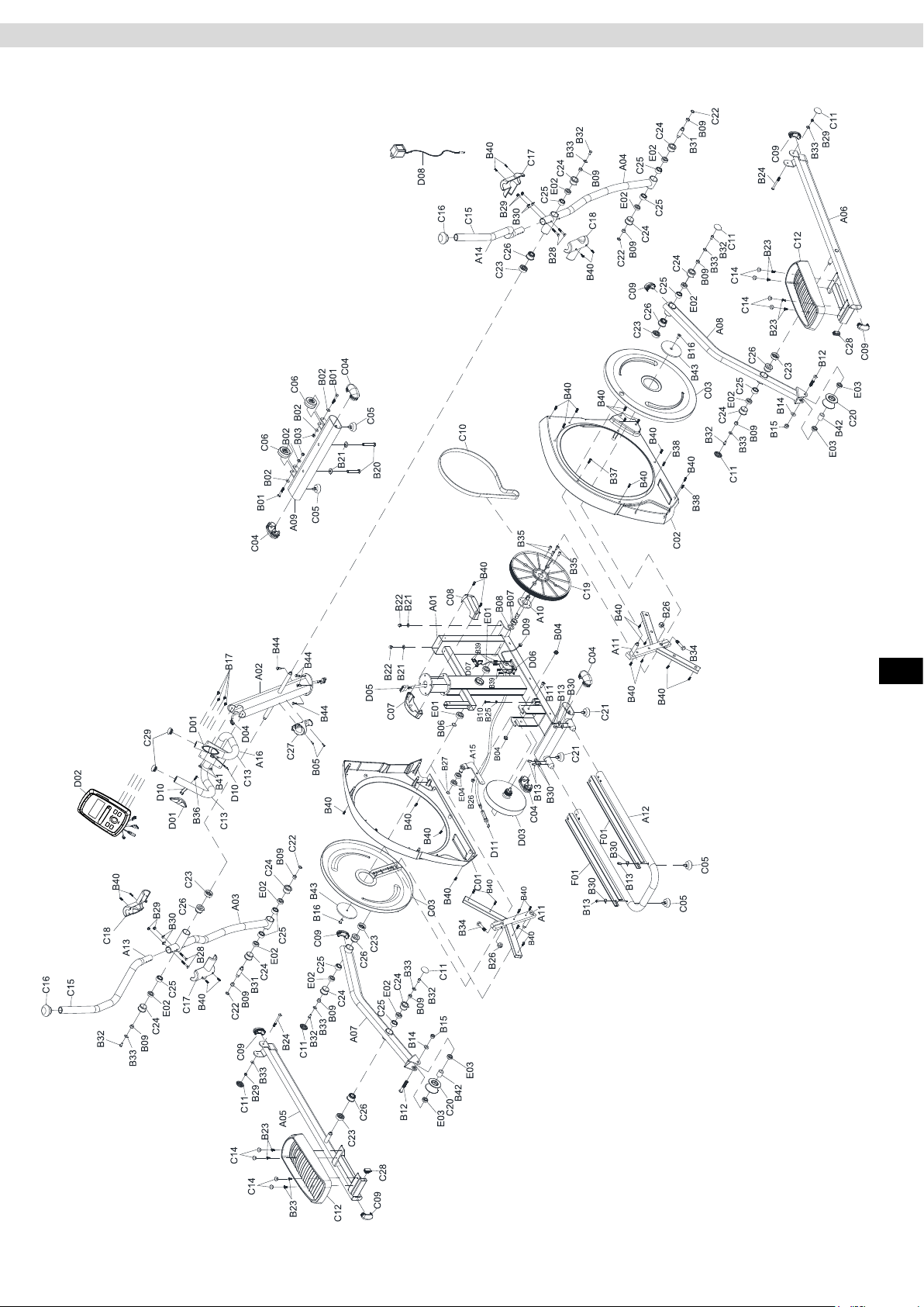
Exploded Drawing
ENG
27
Page 28
Spare Parts List
Part No. Description Qty
A01 Welded,Main Frame 1
A02 Welded,Upright Support 1
A03 Welded,Dual Action Tube Left 1
A04 Welded,Dual Action Tube Right 1
A05 Welded,Foot Pedal Tube Left 1
A06 Welded,Foot Pedal Tube Right 1
A07 Welded,Foot Tube Left 1
A08 Welded,Foot Tube Right 1
A09 Front Stabilizer Tube 1
A10 Welded,Shaft Pulley 1
A11 Welded,Crank Assembly 2
A12 Tube,Guide Rails 1
A13 Dual Action Handlebar Left 1
A14 Dual Action Handlebar Right 1
A15 Welded,Tension Wheel Arm 1
A16 Hand Pulse Handle Bar 1
B01 1/4" Hex Bolt 2
B02 1/4" Washer 4
B03 1/4" Lock Nut 2
B04 3/8"Nut 2
B05 M5 Screw 2
B06 C Clip 1
B07 M21 Wave Washer 2
B08 M20 Washer 1
B09 Bushing Spacer 10
B10 M8 Hex Head Screw 1
B11 M10 Allen Key Screw 1
B12 M12 Allen Key Screw 2
B13 M8 Allen Key Screw 6
B14 1/2" Washer 2
B15 M12 Lock Nut 2
B16 M8 Screw 2
B17 Screws For Computer 4
B20 M5 Bolt 2
B21 3/8" Hex Head Screw 4
B22 3/8" Dome Nut 2
B23 M6 Allen Key Screw 8
B24 M8 Allen Key Screw 2
B25 M8 Black Nut 1
B26 M10 Lock Nut 3
B27 C Clip 1
B28 M8 Carriage Bolt 4
B29 M8 Lock Nut 6
B30 M8 Curve Washer 8
B31 Shaft For Dual Action Arm Pivot 2
B32 M8 Hex Head Screw 6
B33 5/16" Washer 8
B34 M10 Hex Head Screw 2
B35 M8 Allen Key Screw 4
B36 M3 Sheet Metal Screw 2
B37 3/16" Sheet Metal Screw 1
B38 M3 Sheet Metal Screw 2
Part No. Description Qty
B39 M4 Sheet Metal Screw 6
B40 M5 Sheet Metal Screw 35
B41 M8 Screw 2
B42 Bushing 2
B43 Zinc Plate 2
B44 M8 Hex Head Screw 4
C01 Main Cover Right 1
C02 Main Cover Left 1
C03 Disc Cover 2
C04 End Cap for Stabilizer Bar 4
C05 Height Adjuster 4
C06 Transportation Wheel 2
C07 Upright Joint Cover Left 1
C08 Upright Joint Cover Right 1
C09 End Cap for Foot Pedal Tube 6
C10 Belt 1
C11 Nut Cap 6
C12 Foot Pedal 2
C13 Foam Grip 2
C14 Foot Pedal Plug 8
C15 Foam Grip 2
C16 Dual Action Arm Knob 2
C17 Pivot Cover Left 2
C18 Pivot Cover Right 2
C19 Pulley 1
C20 Roller 2
C21 Height Adjuster 4
C22 Washer 4
C23 Spacer 6
C24 Bearing Bushing 10
C25 Bearing Housing 10
C26 Bushing 6
C27 Water Bottle Holder 1
C28 Square End Cap 2
C29 End Cap 2
D01 Hand Pulse Sensor 1
D02 Computer 1
D03 Magnetic Flywheel 1
D04 Cable 1
D05 Cable 1
D06 Motor with cable 1
D07 Sensor Cable 1
D08 AC Adapter 1
D09 AC Plug Cable 1
D10 Hand Pulse Cable 1
D11 Motor Tension Cable 1
E01 Bearing 6004 2
E02 Bearing 6003 10
E03 Bearing 6001 4
E04 Bearing 6203 2
F01 Aluminum Guide Rail 2
28
Page 29
FAQ
My training device makes noises during training – is this normal?
Your MAXXUS® training device is equipped with high-quality ball-bearings and a grooved belt. In addition, it also has a high-quality
magnetic braking system which is completely wear and friction free. All these extremely high-quality components ensure that all func-
tional noises are very much reduced. Your MAXXUS® training device is one of the quietest products available in the tness market.
However, it is possible and normal that slight mechanical noises are noticeable during training. These mechanical noises, which either
continually or sometimes occur at certain intervals are created by the very high rotational speed of the ywheel. Also, moving parts may
generate sounds during training, which are amplied by the hollow metal tubes of the frame. It is also quite normal for running noise to
get louder during your workout. This can be explained by an increase in training speed and by the device components heating up and
expanding during training.
The cockpit does not show anything in the display when I turn it on.
Check if the power cable is both attached correctly to the device and properly plugged into the socket, and/or if it is damaged. Check if
the control cable has been pinched or jammed during assembly and / or if the connector has come loose.
The pulse rate value is not shown or is indicated incorrectly
Please refer to the „Pulse & Heart Rate Measurement” sections in this manual.
The hand pulse rate sensors are not functioning
Check if the hand sensor cables have been pinched or jammed during assembly.
The speed and distance values are indicated to be„0“during training.
Check if the control cable has been pinched or jammed during assembly and/or if the connections have come loose.
My training device makes creaking noises during training.
Check if the training device is standing straight and at on the ground. If not, re-adjust the foot stands. Check if the screws at the articulated joint between the pendulum tubes and the pedal arms are tightened securely.
My feet fall asleep during training.
The reason for this is often that training shoes are done up too tightly. Your feet will expand when you are under exertion and so you
should do up your shoes more loosely. You can also get advice regarding this from sports shops or specialist running shoe shops.
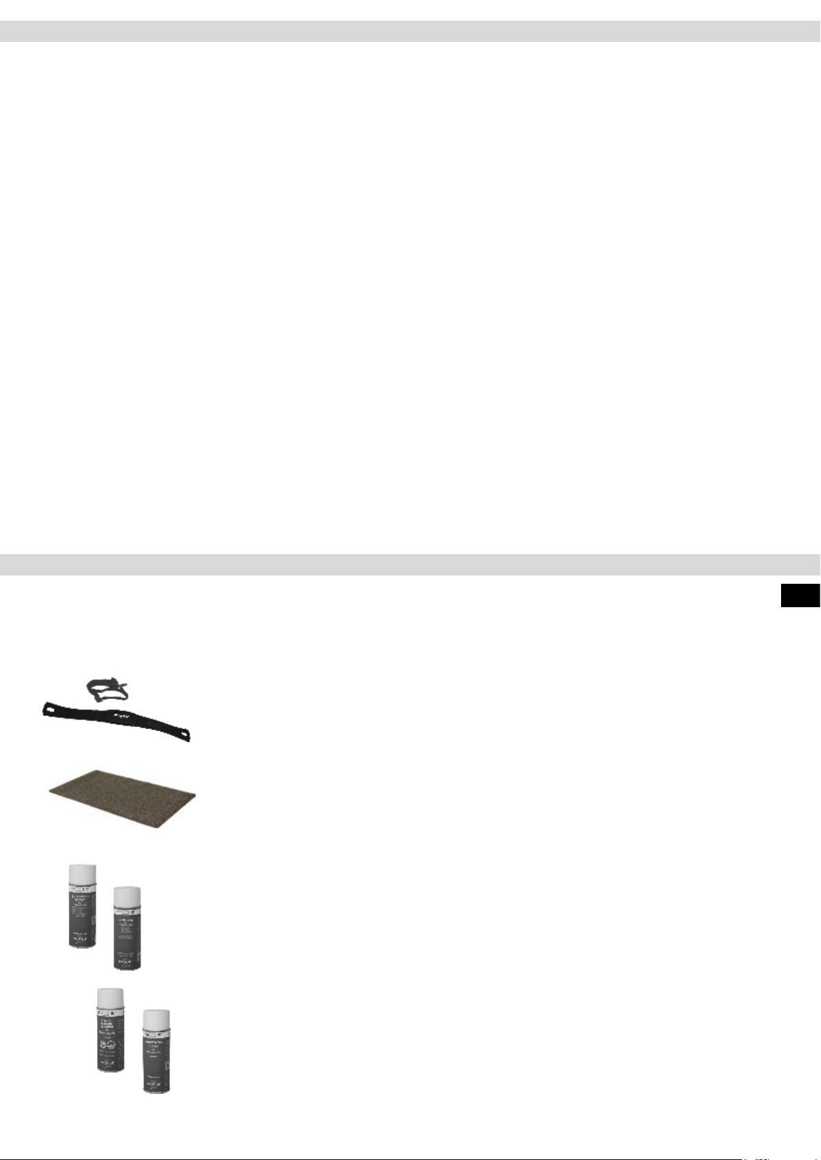
Recommended Accessories
These accessories are best suited for use with your training device. All products are
available from our online shop at www.maxxus.com.
POLAR® Transmitter Chest Belt T34 (uncoded)
Chest strap for determining the heart rate with optimized transmission ranges. Required
accessory for the application of pulse-controlled programs and for continuous determination of the current heart rate.
MAXXUS® Floor Protection Mats
Due to its extreme density and material thickness of 0,5cm, these mats provide perfect
protection for oors and oor coverings against damaging, scratches and soiling through
body sweat. Noise caused by running and movement is signicantly reduced.
Available in the following sizes:
− 160 x 90 cm
− 210 x 100 cm
MAXXUS® Degreaser Spray - Optimum cleaner for cleaning o dirt and maintaining the
guide pipes and roller surfaces.
ENG
MAXXUS® Lubricating Spray – Optimum lubrication for guide pipes.
MAXXUS® Anti-Static Spray – Eective against the static charges created in frames,
clothing and training computers. Devices which are located on carpets or synthetic oors
will become statically charged. MAXXUS ® Anti-Static Spray will deter this.
Synthetic surfaces treated with MAXXUS® Anti-Static Spray do not attract dust as quick-
ly and will remain clean for longer.
MAXXUS® Special Foam Cleaner – Use for regular cleaning of your training device.
Plastic covers and metal frames can be easily cleaned and perfectly maintained with
MAXXUS ® Special Foam Cleaner. It is also suitable for cleaning pulse belts and other
training accessories.
29
Page 30
Warranty*
For MAXXUS® Support Team to help you as quickly as possible with service, we will require certain information
about your tness device and about you. To nd the exact spare parts required, we will need the product name,
date of purchase and serial number.
If necessary, please ll out completely the Service Contract form attached to this User Manual and send it to us
by post or you are welcome to use our online form “Service Contract” which you will nd under the “Service”
section at www.maxxus.com
Areas of Application & Warranty Periods
Depending on the model, tness devices from MAXXUS® are suitable for use in dierent areas. Find the appropriate area of use for your tness device from the “Technical Data” in this User Manual.
Home Use:
Exclusively for private use
Warranty Period: 2 Years
Semi-Professional Use:
Use under instruction in hotels, physiotherapy practices, etc.
Use in a tness studio or similar establishment is hereby excluded!
Warranty Period: 1 Year
Professional Use:
Use in a tness studio or similar establishment under supervision by trained personnel.
Warranty Period: 1 Year
Use of your training device in an area which is not suitable for your device will cause immediate expiry of its
guarantee and cancel your right to claim warranty!
Sole private use and warranty period of 2 years assumes that the purchase invoice is made out to the end user.
Proof of Purchase and Serial Number
To claim your right to service works within the warranty period we will in each case require proof of purchase.
Keep your proof or purchase or purchase invoice in a safe place and in warranty cases send us a copy together
with your Service Contract. This will ensure that we can process the service work as quickly as possible. So
that we can identify which model version requires to be serviced correctly, we will require; Product Name, Serial
Number and Date of Purchase.
Terms and Conditions of Warranty:
The warranty period for your training device starts on the date of purchase and applies solely to products which
were purchased directly from the MAXXUS Group GmbH & Co KG or one of the MAXXUS Group GmbH & Co
KG direct and authorised distribution partners.
The warranty covers defects caused by production or material faults and only apply to devices purchased in
Germany. The warranty does not apply to damages or defects caused by culpable improper use, negligent
or purposeful destruction, lack or failure to carry out maintenance and/or cleaning measures, force majeure,
operational causes and to normal wear and tear, damages caused by penetration of liquids, damage caused by
repairs or modications made with spare parts from a dierent supplier. The warranty also does not apply for
damages due to faulty assembly or damages which occur because of faulty assembly. Certain component parts
will wear out during use or from normal wear and tear. This includes for example:
▪ Ball bearings ▪ Bearing bushings ▪ Bearings ▪ Drive belts ▪ Rollers
▪ Switches and push-buttons ▪ Treadmill belts (bands) ▪ Treadmill decks (running deck)
Signs of wear and tear on wearing parts are not items covered under the warranty.
For assistance with warranty service or warranty repair enquiries for devices not in Germany, please contact our
Service Department at MAXXUS Group GmbH & Co KGM by sending an Email to: [email protected] and we
will be happy to help.
Service Outside the Warranty and Ordering Spare Parts
The MAXXUS® Service Team is happy to be of assistance to help solve any problems with faults which may
arise following expiry of the warranty period, or in cases of defects arising which are not covered by the
warranty.
In this case please contact us by email direct to:
Orders for Spare Parts or Worn Parts should be sent along with information on the Product Name, spare part
description and number and the quantity required to:
Please be informed that additional xing materials such as screws, bolts, washers etc are not included in the
scope of delivery for individual spare parts. These should be ordered separately.
*Version: June/2016
30
Page 31
Service Contract
Device Details
Product Name: CX 5.1
Serial Number: _______________________________________
Date of Purchase: _____________________________________
Accessories: _________________________________________
Type of Use:
Private Use
Personal Details
Company: ___________________________________________
First Name: __________________________________________
Street: ______________________________________________
Post Code / Town/City: _________________________________
E-Mail: _____________________________________________
Fax. No.*: ___________________________________________
* The elds marked with an asterisk are optional. The remaining elds are mandatory elds that must be completed.
Fault Description
Please enter a short description of the error as precisely as possible below:
(For example, when, where and how does the error occur? Frequency, after which period, at what Use, etc ....)
Product Group: Cross-Trainer
Invoice Number: ______________________________________
Where Purchased: ____________________________________
________________________________________________
Commercial Use
Contact Person: _______________________________________
Second Name: ________________________________________
House Number: _______________________________________
Country: _____________________________________________
Tel.No.: _____________________________________________
Mobile No.*: __________________________________________
A copy of the proof of purchase / invoice / receipt is attached.
I accept the General Terms and Conditions of MAXXUS® Group GmbH & Co. KG.
I hereby instruct the company MAXXUS® Group GmbH & Co. KG to repair the above defects. In Warranty cases I will not be charged
for the cost. The costs for repairs which are excluded from liability for defects in quality will be charged to me and must be settled
immediately. In cases of repairs carried out on site, our sta are entitled to collect payment. This agreement is conrmed with here with
my signature.
Date Location Signature
Please be aware that contracts can only be processed if this form has been completed in full. Be sure to attach a copy of your purchase
invoice. Send the fully completed Service Contract to:
ENG
Post*: Maxxus Group GmbH & Co KG, Service Department, Zeppelinstr. 2, 64331 Weiterstadt
Fax: +49 (0) 6151 39735 400
E-Mail**: [email protected]
* Please stamp with sucient postage – letters which are not sent postage paid will unfortunately not be accepted.
** Submission by E-Mail is only possible as a scanned document with original signature.
You are welcome to use our online form “Service Contract” which you will nd under the “Service” section at www.maxxus.com
31
Page 32
Maxxus Group GmbH & Co. KG
Zeppelinstr. 2
D-64331 Weiterstadt
Germany
E-Mail: [email protected]
www.maxxus.com
32
 Loading...