

Page 1
Page 2

MAXX-LINK MLX-100
MAXX-LINK MLX-100
UNIVERSAL AMPLIFIER BRIDGING & SYNCHRONIZATION MODULE
UNIVERSAL AMPLIFIER BRIDGING & SYNCHRONIZATION MODULE
The MLX-100 Maxx-Link is a unique problem solving signal processor. The Maxx-Link
The MLX-100 Maxx-Link is a unique problem solving signal processor. The Maxx-Link
allows interconnecting (a.k.a. Linking) of up to five amplifier pairs in Master/Slave
allows interconnecting (a.k.a. Linking) of up to five amplifier pairs in Master/Slave
configurations to a single subwoofer or multiple subwoofers. This is an incredible
configurations to a single subwoofer or multiple subwoofers. This is an incredible
solution for expanding your system and allowing for linking of non linkable mono block
solution for expanding your system and allowing for linking of non linkable mono block
amplifiers.
amplifiers.
INDEX PAGE INDEX PAGE
Feature Descriptions...........................................................................................................................................1
Feature Descriptions...........................................................................................................................................1
End Panel, Front Mount Controls, and Remote Module Drawings....................................................................2
End Panel, Front Mount Controls, and Remote Module Drawings....................................................................2
Application/ Diagram...........................................................................................................................................3
Application/ Diagram...........................................................................................................................................3
Application/ Diagram.......................................................................................................................................4 - 5
Application/ Diagram.......................................................................................................................................4 - 5
Application/ Diagram........................................................................................................................................6-7
Application/ Diagram........................................................................................................................................6-7
Single and dual sub applications, independent and
Single and dual sub applications, independent and
Troubleshooting and diagnostics.......................................................................................................................8
Troubleshooting and diagnostics.......................................................................................................................8
Product Warranty.................................................................................................................................................9
Product Warranty.................................................................................................................................................9
Linking 2 MLX-100s using Master/Slave operations
Linking 2 MLX-100s using Master/Slave operations
Mono Bridging 2 standard mono amplifier with no
Mono Bridging 2 standard mono amplifier with no
Master/Slave feature to a single subwoofer
Master/Slave feature to a single subwoofer
bridged mode applications
bridged mode applications
The contents of this manual may not be reproduced or copied without the written consent of MAXXSONICS USA, Inc.
Page 3

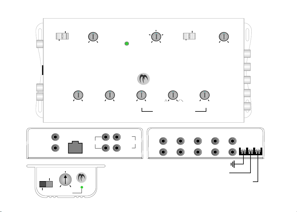
MAXX-LINK MLX-100 BRIDGING MODULE FEATURE DESCRIPTIONS
END PANEL CONNECTIONS
MASTER OUT / SLAVE IN: The Master Out sends master signal to another MLX-100.
The Slave In receives a Master signal and all controls are bypassed on the unit.
BR-1 REMOTE CONTROL: Using an Rj45 cable, the BR-1 Bass Remote Module plugs
directly into the MLX-100 and allows you to adjust the Level from -20dB to 0 dB as well
as Normal and Bypass operations.
NORMAL: BR-1 is fully adjustable from -20dB to 0dB.
BYBASS: BR-1 is set to 0dB fixed regardless of where the dial is set.
LINE INPUT: Accepts unbalanced RCA inputs from 0.2 volts to 9 volts.
LINE OUTPUT: The unbalanced RCA outputs are Left and Right Full Range outputs.
BRIDGING OUTPUTS: A+/- through E+/- provide signal output to up to 10 linked mono
block amplifiers.
TOP MOUNT CONTROLS
MASTER/ SLAVE MODE: Should be set in Master position when controlling amplifiers
and Slave position when it is being controlled by another MLX-100.
LOW PASS FILTER: The Low Pass Filter is fully adjustable from 35Hz to 250Hz at
24dB per Octave.
SYSTEM DIAGNOSTICS: The MLX-100 has built-in monitoring devices. The light
turns RED when the signal is Clipped and Green when it is 9 volts.
OUTPUT LEVEL: Fully adjustable signal output to amplifiers from 1 volt to 9 volts.
TEST TONE: Selectable OFF/ON 65Hz Test Tone provides a constant tone for testing
and tuning the output level on the amplifiers.
SUBSONIC FILTER: The Subsonic Filter is fully adjustable from 15Hz to 35Hz at 24dB
per Octave.
INPUT LEVEL: The Input Level (gain) control allows you to match the MLX-100 input
sensitivity to the Output Level of the source from 9 volts to 0.2 volts.
PHASE: The Phase Shift is fully adjustable from 0 to 180 degrees.
PARAMETRIC BASS EQ:
BOOST: The Bass Boost is fully adjustable from 0dB to 10dB.
BANDWIDTH: The Bandwidth is fully adjustable from narrow to wide.
FREQUENCY: The Frequency is fully adjustable from 30Hz to 100Hz.
1
Page 4
2
MAXX-LINK MLX-100 BRIDGING MODULE
MASTER OUT
SLAVE IN
BYPASS
NORMAL
SLAVE
MASTER
MODE
BR-1 REMOTE
CONTROL
-6dB
-20dB 0dB
LEVEL
5V
7V3V
LOW PASS
FILTER
24 dB/OCT
RED - CLIP
GREEN - 9V
OUTPUT
LEVEL
TEST TONE
MAXX-LINK
MLX-100
0.2V 180 +10 dB 100Hz9V 0 0dB 30Hz
INPUT
LEVEL
RED - CLIP
GREEN - 9V
PHASE BOOST
INPUT
FULL RANGE
BR-1 Remote Module
NORMAL OPERATION: Allows use of variable
LEVEL control.
BYPASS OPERATION: Ouput is fixed at 0dB.
By switching between NORMAL and BYPASS
operation, you can create BURSTS of high to
low audio output.ie: Burping
LEFT
RIGHT
INPUT
BANDWIDTH FREQUENCY
PARAMETRIC BASS EQ
BRIDGING OUTPUTS
A B C D E
+ + + + +
- - - - -
ON
OFF
65Hz
15Hz35Hz
SUBSONIC
FILTER
24 dB/OCT
CHASSIS GROUND
REMOTE TURN-ON
TO BATTERY + 12v VIA 1amp FUSE
35Hz250Hz 1V 9V
GND REM
+12V
Page 5

MAXX-LINK MLX-100 BRIDGING MODULE APPLICATIONS
Linking 2 MLX-100s using Master/Slave operations
This application illustrates the method of linking 2 MLX-100’s using the Master/Slave features.
1. Connect the full range RCA outputs from the headunit to the MLX-100 #1’s inputs.
2. Connect a single RCA from MLX-100 #1’s MASTER OUT to MLX-100 #2’s SLAVE IN.
3. Swicth MLX-100 #1 into MASTER MODE and MLX-100 #2 in SLAVE MODE.
4. Adjust MLX-100 #2 as follows:
- The LOW PASS FILTER should be turned to 250Hz.
- The OUTPUT LEVEL should be turned to 1V.
- The SUBSONIC FILTER should be turned to 15Hz.
- The INPUT LEVEL should be at the 12 o’clock position.
- The PHASE should be turned to 0.
- The BOOST should be turned to 0dB.
- The Bandwidth should be turned all the way to the right.
- The FREQUENCY should be turned to 100Hz.
5. Connect POWER, GROUND and REMOTE to each MLX-100.
Now MLX-100 #1 controls MLX-100 #2 and you can run up to 10 linked pairs of amplifiers. Match all amplifiers as instructed
in the future application instructions.
MASTER OUT
SLAVE IN
SLAVE
MASTER
LOW PASS
MODE
BR-1 REMOTE
CONTROL
INPUT
FULL RANGE
LEFT
RIGHT
INPUT
FILTER
24 dB/OCT
0.2V 180 +10 dB 100Hz0.9V 0 0dB 30Hz
INPUT
LEVEL
MASTER
5V
7V3V
RED - CLIP
GREEN - 9V
MAXX-LINK
PHASE BOOST
OUTPUT
LEVEL
MLX-100
PARAMETRIC BASS EQ
BANDWIDTH FREQUENCY
ON
OFF
TEST TONE
65Hz
#1
15Hz35Hz
SUBSONIC
FILTER
24 dB/OCT
+12V
GND REM
35Hz250Hz 1V 9V
BRIDGING OUTPUTS
A B C D E
- - - - -
+ + + + +
Signal From Source Unit
(RADIO/CD PLAYER)
-6dB
BYPASS
NORMAL
-20dB 0dB
LEVEL
RED - CLIP
GREEN - 9V
SLAVE IN
FULL RANGE
RIGHT
MASTER OUT
SLAVE
MASTER
LOW PASS
MODE
BR-1 REMOTE
CONTROL
INPUT
LEFT
INPUT
FILTER
24 dB/OCT
0.2V 180 +10 dB 100Hz0.9V 0 0dB 30Hz
INPUT
LEVEL
SLAVE
5V
7V3V
RED - CLIP
GREEN - 9V
MAXX-LINK
PHASE BOOST
OUTPUT
LEVEL
MLX-100
PARAMETRIC BASS EQ
BANDWIDTH FREQUENCY
ON
OFF
TEST TONE
65Hz
#2
15Hz35Hz
SUBSONIC
FILTER
24 dB/OCT
+12V
GND REM
35Hz250Hz 1V 9V
BRIDGING OUTPUTS
A B C D E
- - - - -
+ + + + +
3
Page 6

4
MAXX-LINK MLX-100 BRIDGING MODULE APPLICATIONS
Mono bridging 2 standard mono amplifiers with no Master/Slave feature to a single subwoofer
This application illustrates the method of linking 2 Mono amplifiers to a single subwoofer.
1. Connect the full range RCA outputs from the headunit to the MLX-100 inputs.
2. Connect the RCA’s from the MLX-100 (A+ and A-) BRIDGING OUTPUTS to the amplifier INPUTS as shown.
3. The amplifier settings need to be adjusted as follows:
- The LOW PASS FILTER should be turned towards the highest frequency. (EXAMPLE: LOW PASS range = 35Hz to 250Hz, adjust to 250Hz)
- The SUBSONIC FILTER should be turned towards the lowest frequency. (EXAMPLE: SUBSONIC range = 15Hz to 35Hz, adjust to 35Hz)
- The PHASE should be at 0.
- The BASS BOOST/BASS EQ should be at 0dB.
- The LEVEL(gain) control should be turned to the 12 o’clock position.
4. The INPUT LEVEL control on the MLX-100 should be set to match the output signal voltage from your headunit.
5. The MLX-100 LOW PASS FILTER, SUBSONIC FILTER and PARAMETRIC BASS EQ settings should be adjusted for desired listening.
6. The MODE switch should be in the MASTER position.
7. The OUTPUT LEVEL should be at 1 Volt.
At this point you are ready to balance the speaker output from your amplifiers. For this procedure you will need a Digital Voltmeter.
- Switch the MLX-100 TEST TONE switch to the ON position.
- Adjust your Voltmeter so that it is measuring Volts AC.
- Connect the positive Voltmeter lead to the (+)POSITIVE SPEAKER TERMINAL on amplifier #1.
- Connect the negative Voltmeter lead to the (-)NEGATIVE SPEAKER TERMINAL on amplifier #1.
- Turn the audio system on, turn the volume all the way down, and ensure that there is no audio CD in your CD player.
- Start off with the input LEVEL(gain) settings of the 2 amplifiers at top dead center, or the 12 o’clock positions.
- While measuring the Voltage AC on amplifier #1, continue adjusting level control until you measure anywhere from 4-6 Volts. At that point, write down the
voltage on a piece of paper.
-Connect the voltmeter to the speaker terminals of amplifier #2.
- Now adjust the input gain control of amplifier #2 for the same voltmeter reading as you had noted down .
8. Once the amplifiers have matching output voltages, you should turn the 65Hz TEST TONE to the OFF position.
9. Connect the speaker + terminal to the POSITIVE SPEAKER TERMINAL of amplifier #1.
Connect the speaker - terminal to the POSITIVE SPEAKER TERMINAL of amplifier #2.
Connect a wire link between the NEGATIVE SPEAKER TERMINALS of the two amplifiers.
10. Use the OUTPUT LEVEL adjustment to obtain the desired audio level.
11. The steps outlined in #8 may have to be repeated if you cannot get full power out of the amplifiers, in which case, start off with their input gain controls set for higher gain.
Note: Up to 10 amplifiers can be connected in this manner,
by also using MLX-100 outputs B thru E.
Page 7

Mono bridging 2 standard mono amplifiers with no Master/Slave feature to a single subwoofer
MASTER OUT
SLAVE IN
SLAVE
MASTER
LOW PASS
MODE
BR-1 REMOTE
CONTROL
INPUT
FULL RANGE
LEFT
RIGHT
INPUT
FILTER
24 dB/OCT
0.2V 180 +10 dB 100Hz0.9V 0 0dB 30Hz
INPUT
LEVEL
Signal From Source Unit
(RADIO/CD PLAYER)
MAXX-LINK MLX-100 BRIDGING MODULE APPLICATIONS
Mono Block Amplifiers
INPUT
R
L
-6dB
BYPASS
RED - CLIP
LEVEL
5V
OUTPUT
LEVEL
PARAMETRIC BASS EQ
GREEN - 9V
ON
7V3V
OFF
TEST TONE
65Hz
BANDWIDTH FREQUENCY
15Hz35Hz
SUBSONIC
FILTER
24 dB/OCT
#1
+12V
GND REM
35Hz250Hz 1V 9V
BRIDGING OUTPUTS
A B C D E
INPUT
R
L
- - - - -
+ + + + +
-20dB 0dB
NORMAL
RED - CLIP
GREEN - 9V
MAXX-LINK
MLX-100
PHASE BOOST
#2
++
Speaker Terminals
--
Speaker Terminals
12ga.
Wire link
5
Page 8

6
MAXX-LINK MLX-100BRIDGING MODULE APPLICATIONS
Mono bridging 4 standard amplifiers with no Master/Slave feature to 2 subwoofers
This application illustrates the method of linking 4 Mono amplifiers to 2 subwoofers.
1. Connect the full range RCA outputs from the headunit to the MLX-100 inputs.
2. Connect the RCA’s from the MLX-100 (A+ and A-) BRIDGING OUTPUTS to amplifiers 3 & 4 INPUTS as shown. Repeat this process for amplifiers 1 & 2 through B+ and -.
3. The amplifier settings need to be adjusted as follows:
- The LOW PASS FILTER should be turned towards the highest frequency. (EXAMPLE: LOW PASS range = 35Hz to 250Hz, adjust to 250Hz)
- The SUBSONIC FILTER should be turned towards the lowest frequency. (EXAMPLE: SUBSONIC range = 15Hz to 35Hz, adjust to 35Hz)
- The PHASE should be at 0.
- The BASS BOOST/BASS EQ should be at 0dB.
- The LEVEL(gain) control should be turned to the 12 o’clock.
4. The INPUT LEVEL control on the MLX-100 should be set to match the output signal voltage from your headunit.
5. The MLX-100 LOW PASS FILTER, SUBSONIC FILTER and PARAMETRIC BASS EQ settings should be adjusted for desired listening.
6. The MODE switch should be in the MASTER position.
7. The OUTPUT LEVEL should be at 1Volt.
At this point you are ready to balance the speaker output from your amplifiers. For this procedure you will need a Digital Voltmeter.
- Switch the MLX-100 TEST TONE switch to the ON position.
- Adjust your Voltmeter so that it is measuring Volts AC.
- Connect the positive Voltmeter lead to the (+)POSITIVE SPEAKER TERMINAL on amplifier #1.
- Connect the negative Voltmeter lead to the (-)NEGATIVE SPEAKER TERMINAL on amplifier #1.
- Turn the audio system on, turn the volume all the way down, and ensure that there is no audio CD in your CD player.
- Start off with the input LEVEL(gain) settings of the 4 amplifiers at top dead center, or the 12 o’clock position.
- While measuring the Voltage AC on amplifier #1, continue adjusting the headunit until you measure anywhere from 4-6 Volts. At that point, write down the
voltage on a piece of paper.
- Connect the voltmeter to the speaker terminals of amplifier #2, then #3 and finally #4.
- Now adjust the input gain control of amplifiers #2 through #4 for the same voltmeter reading as you had noted down from amplifier #1.
8. Once the amplifiers have matching output voltages, you should turn the 65Hz TEST TONE to the OFF position.
9. Connect the speaker + terminal from subwoofer #1 to the POSITIVE SPEAKER TERMINAL of amplifier #1.
Connect the speaker - terminal from subwoofer #1 to the POSITIVE SPEAKER TERMINAL of amplifier #2.
Connect a wire link between the NEGATIVE SPEAKER TERMINALS of the two amplifiers.
-Repeat this process for subwoofer #2 and amplifiers #3 and #4.
10. Use the OUTPUT LEVEL adjustment to obtain the desired audio level.
11. The steps outlined in #8 may have to be repeated if you cannot get full power out of the amplifiers, in which case, start off with their input gain controls set for higher gain.
Page 9

MAXX-LINK MLX-100 BRIDGING MODULE APPLICATIONS
Mono bridging 4 standard amplifiers with no
Master/Slave feature to 2 subwoofers
-6dB
BYPASS
RED - CLIP
-20dB 0dB
NORMAL
LEVEL
MASTER OUT
SLAVE IN
SLAVE
MASTER
MODE
BR-1 REMOTE
CONTROL
INPUT
FULL RANGE
LEFT
RIGHT
INPUT
LEVEL
INPUT
RED - CLIP
LOW PASS
GREEN - 9V
FILTER
24 dB/OCT
MAXX-LINK
MLX-100
0.2V 180 +10 dB 100Hz0.9V 0 0dB 30Hz
PHASE BOOST
Signal From Source Unit
(RADIO/CD PLAYER)
7
GREEN - 9V
5V
7V3V
OUTPUT
LEVEL
BANDWIDTH FREQUENCY
PARAMETRIC BASS EQ
OFF
TEST TONE
65Hz
ON
35Hz250Hz 1V 9V
15Hz35Hz
SUBSONIC
FILTER
24 dB/OCT
Mono Block Amplifiers
INPUT
R
L
Speaker Terminals
+
#1
-
#1
INPUT
R
L
+
+12V
GND REM
INPUT
R
L
BRIDGING OUTPUTS
A B C D E
- - - - -
+ + + + +
#2
#3
-
+
-
12ga.
Wire link
#2
INPUT
R
L
+
#4
-
Speaker Terminals
12ga.
Wire link
Page 10

TROUBLESHOOTING A SYSTEM
The key to finding the problem in a troubled sound system is to isolate parts of that system in a logical fashion to track down the fault.
The key to finding the problem in a troubled sound system is to isolate parts of that system in a logical fashion to track down the fault.
Description of the Diagnostic system built into the MLX-100 Maxx-Link Bridging Module:
Description of the Diagnostic system built into the MLX-100 Maxx-Link Bridging Module:
1. Clipping Indicator: Red Illumination when signal is clipped.
1. Clipping Indicator: Red Illumination when signal is clipped.
2. Normal Operation: Green Illumination, when signal is unclipped up to 9volts.
2. Normal Operation: Green Illumination, when signal is unclipped up to 9volts.
The diagnostic system will not shut down the MLX-100 or the amplifier(s), although the amplifier(s) own protection circuitry may shut the
The diagnostic system will not shut down the MLX-100 or the amplifier(s), although the amplifier(s) own protection circuitry may shut the
amplifier(s) down should a fault status occur. At which time you will need to consult the owners manual for that particular amplifier.
amplifier(s) down should a fault status occur. At which time you will need to consult the owners manual for that particular amplifier.
Low output power
Low output power
1 - Check that level controls have been set up properly.
1 - Check that level controls have been set up properly.
2 - Make sure that the battery voltage, as measured at the amplifier’s and MLX-100’s +12 volt and ground terminals, is 11 volts or more.
2 - Make sure that the battery voltage, as measured at the amplifier’s and MLX-100’s +12 volt and ground terminals, is 11 volts or more.
3 - Check all +12 volt and ground connections.
3 - Check all +12 volt and ground connections.
Fuses blowing
Fuses blowing
1 - Insure that the voltage to the unit does not exceed 15 volts.
1 - Insure that the voltage to the unit does not exceed 15 volts.
2 - A short on the main +12 volt cable from the battery to the vehicle chassis will cause the main fuse to blow.
2 - A short on the main +12 volt cable from the battery to the vehicle chassis will cause the main fuse to blow.
3 - If the MLX-100 is blowing fuses continually with only +12 volt, ground and remote leads connected, the unit may be faulty.
3 - If the MLX-100 is blowing fuses continually with only +12 volt, ground and remote leads connected, the unit may be faulty.
System does not turn on
System does not turn on
1 - Check all fuses.
1 - Check all fuses.
2 - Check all connections.
2 - Check all connections.
3 - Measure the +12 volt and remote turn on voltages at the amplifier and MLX-100 terminals. If these are non existent or low, take
3 - Measure the +12 volt and remote turn on voltages at the amplifier and MLX-100 terminals. If these are non existent or low, take
voltage measurements at fuse holders, distribution blocks, the head unit’s +12 volt and remote leads to localize the problem.
voltage measurements at fuse holders, distribution blocks, the head unit’s +12 volt and remote leads to localize the problem.
Noise problems
Noise problems
System noise can be divided into two categories, hiss, and electrical interference.
System noise can be divided into two categories, hiss, and electrical interference.
Hiss, or white noise
Hiss, or white noise
1 - High levels of white noise usually occur when level controls are turned up too high - readjust according to the procedures in the
1 - High levels of white noise usually occur when level controls are turned up too high - readjust according to the procedures in the
appropriate application section.
appropriate application section.
2 - Another major problem that can cause excessive hiss, is a noisy head unit - unplug the MLX-100 input RCA cables, and if the hiss level
2 - Another major problem that can cause excessive hiss, is a noisy head unit - unplug the MLX-100 input RCA cables, and if the hiss level
reduces, the source unit is at fault.
reduces, the source unit is at fault.
Electrical interference
Electrical interference
The inside of an automobile is a very hostile electrical environment. The multitude of electrical systems, such as the ignition system,
The inside of an automobile is a very hostile electrical environment. The multitude of electrical systems, such as the ignition system,
alternator, fuel pumps, air conditioners, to mention just a few, create radiated electrical fields, as well as noise on the +12 volt supply and
alternator, fuel pumps, air conditioners, to mention just a few, create radiated electrical fields, as well as noise on the +12 volt supply and
ground. Remember to isolate the problem - first unplug MLX-100 input RCA cables, if the noise is still present, check the speaker leads, if
ground. Remember to isolate the problem - first unplug MLX-100 input RCA cables, if the noise is still present, check the speaker leads, if
not, plug the RCA’s back, and investigate the source driving the MLX-100, one component at a time.
not, plug the RCA’s back, and investigate the source driving the MLX-100, one component at a time.
A ticking or whine that changes with engine RPM:
A ticking or whine that changes with engine RPM:
1 - This problem could be caused by radiation pickup of RCA cables that are too close to a fuel pump or a distributor.
1 - This problem could be caused by radiation pickup of RCA cables that are too close to a fuel pump or a distributor.
2 - Check that the head unit ground is connected straight to the vehicle chassis, and does not use factory wiring for ground.
2 - Check that the head unit ground is connected straight to the vehicle chassis, and does not use factory wiring for ground.
3 - Try to supply the head unit with a clean +12 volt supply directly from the battery +, instead of using a supply from the in dash
3 - Try to supply the head unit with a clean +12 volt supply directly from the battery +, instead of using a supply from the in dash
wiring/fusebox.
wiring/fusebox.
A constant whine:
A constant whine:
This type of noise can be more difficult to pinpoint, but is usually caused by some kind of instability, causing oscillations in the system.
This type of noise can be more difficult to pinpoint, but is usually caused by some kind of instability, causing oscillations in the system.
1 - Check all connections, especially for good grounds.
1 - Check all connections, especially for good grounds.
2 - Make sure that no speaker leads are shorting to exposed metal on the vehicle chassis.
2 - Make sure that no speaker leads are shorting to exposed metal on the vehicle chassis.
3 - RCA cables are notorious for their problematic nature, so check that these are good, in particular the shield connections.
3 - RCA cables are notorious for their problematic nature, so check that these are good, in particular the shield connections.
8
Page 11

MAXX-LINK
MLX-100
As the manufacturer of Maxxsonics, Crunch, MB Quart and Hifonics car audio products,
Maxxsonics Limited Warranty
Maxxsonics USA Inc. Warrants to the original consumer purchaser the amplifier to be free
from defects in material and workmanship for one (1) Year from date of purchase.
All other parts and accessories of the system are warr antied to be free from defects in
material and workmanship for one (1) year from date of purchase. Maxxsonics will
repair or replace at it’s option and free of charge during the warranty period, any system
component that proves defective in materials and workmanship under normal installation,
use and service provided that the product is returned to the authorized Maxxsonics dealer
from where it was purchased. A photo copy of the original receipt must accompany the
product being returned.
Valid purchase receipts will contain the name and address of the authorized reseller.
Any damage to the product as a result of misuse, abuse, accident, incorr ect wiring,
improper installation, alteration of date code or bar code labels, revolution, natural
disaster, or any sneaky stuff because someone messed up, repair or alteration out side
of our factory or authorized service center s and any thing else you have done that you
should not have done is not covered.
This warranty is limited to defective parts and specifically excludes any incidental
or consequential damages connected therewith. This warranty is not to be construed
as an insurance policy.
Warranty on installation labor, removal, re-installation and freight charges are not the
responsibility of Maxxsonics USA Inc.
Warranty products damaged as a result of insuf ficient or improper packing materials
are not covered by this limited warranty and such damaged product will be returned
“as is” at the expense of the owner.
9
Page 12

 Loading...