

Page 1

www.maxxone.com
H.265 NETWORK VIDEO RECORDER
USER MANUAL
Page 2

USER MANUAL
2
Page 3

USER MANUAL
1
Contents
SAFETY INSTRUCTION ............................................................................................... 3
CHAPTER 1 OVERVIEW OF NVR ................................................................................. 1
1.1 FRONT PANEL ............................................................................................................... 1
1.2 REAR PANEL ................................................................................................................. 2
1.3 REMOTE CONTROLLER (FOR REFERENCE ONLY) .................................................................... 3
CHAPTER 2 NVR CONNECTION .................................................................................. 3
2.1 HDD INSTALLATION ....................................................................................................... 3
2.2 WEB CAMERA AND MONITOR CONNECTION ....................................................................... 3
2.3 POWER SUPPLY CONNECTION .......................................................................................... 3
CHAPTER 3 NVR BOOT UP ......................................................................................... 4
3.1 SYSTEM INITIALIZATION ................................................................................................... 4
3.2 STARTUP WIZARD .......................................................................................................... 5
3.3 MAIN INTERFACE ........................................................................................................... 6
CHAPTER 4 NVR MENU ............................................................................................. 6
4.1 MAIN MENU GUIDE ...................................................................................................... 7
4.2 MAIN MENU ................................................................................................................ 8
4.2.1 Parameter .......................................................................................................... 8
4.2.2 Record Search .................................................................................................. 16
4.2.3 Device .............................................................................................................. 20
4.2.4 System ............................................................................................................. 21
4.2.4 Log ................................................................................................................... 23
4.2.5 Advanced ......................................................................................................... 24
4.2.6 Shutdown ........................................................................................................ 25
4.3 MENU LOCK ............................................................................................................... 25
4.4 SPLIT MODE ............................................................................................................... 26
4.5 RECORD SEARCH.......................................................................................................... 26
4.6 MUTE ....................................................................................................................... 26
4.7 START SEQUENCE ......................................................................................................... 26
CHAPTER 5 WEB APPLICATION MANAGER ............................................................... 27
5.1 ACTIVEX CONTROL DOWNLOAD AND INSTALL AT I ON ............................................................. 27
5.2 WEB APPLICATION MANAGER LOGIN .............................................................................. 28
5.3 LIVE INT E RFACE ........................................................................................................... 28
5.3.1 Menu Bar ......................................................................................................... 29
5.3.2 Playback ........................................................................................................... 30
5.3.3 Parameter Setting ............................................................................................ 33
5.3.4 Local Setting .................................................................................................... 41
5.3.5 Logout .............................................................................................................. 41
CHAPTER 6 APPENDIX............................................................................................. 42
Page 4

USER MANUAL
2
6.1 TROUBLESHOOTING ...................................................................................................... 42
6.2 USAGE MAINTENANCE ................................................................................................. 43
CHAPTER 7 WARRANTY .......................................................................................... 44
7.1 LIMITED WARRANTY .................................................................................................... 44
7.2 WARRANTY PERIOD ..................................................................................................... 44
7.3 WARRANTY EXCLUSIONS ............................................................................................... 44
8.4 WARRANTY CLAIMS AND VALIDATION .............................................................................. 45
8.5 LIMITATION OF LIABILITY ............................................................................................... 46
8.6 MISCELLANEOUS PROVISIONS ........................................................................................ 46
8.7 STANDARD WARRANTY CONDITIONS ............................................................................... 46
8.8 REPAIR/REPLACEMENT PROCEDURE ................................................................................ 46
Page 5

USER MANUAL
3
SAFETY INSTRUCTION
Please carefully read the following safety instruction so as to avoid personal injuries and prevent
the equipment and other connection devices from being damaged.
1. Use the power supply included or specified by the manufacturer only
Never operate the equipment using an unspecified or incompatible power supply.
2. Never push objects of any kind through openings of NVR
Never push objects of an y k ind throu gh ope nings of N VR so as to avo id elec tric s hock , f ire or
other accidents.
3. Do not expose the equipment to dust
Clean around the device regularly to prevent overheating and damage.
4. Do not place the equipment under rain or humid environment
Do not place the equipment in humid environments like basements. If the equipment
accidentally comes in contact with water, please unplug the power cable immediately and
contact your local dealer.
5. Keep the surface of the equipment clean and dry
Use soft damp cloth to clean the outer case of NVR (do not use liquid aerosol cleaners).
6. Do not operate if any problems are found
If there are any strange sm ells or sounds com ing from the NVR, unplug the p ower cable and
contact an authorized dealer or service center.
7. Do not try to remove the upper cover during operation
Warning: Do not remove the top cover of NVR so as to avoid electric shock.
8. Handle with care
Physical damage to t his unit can cause it to f ail to operate and you wil l need to contact an
authorized dealer for repair or replacement.
9. Use standard lithium battery (Note: Use the batteries specified by the manufacturer)
After disconnecting t he power supply, if the system clock does not continue to work, please
replace the standard 3V lithium battery on the main board.
Warning: Turn off NVR before replacing the batteries, or you may suffer from a serious electric
shock. Please properly dispose of any used batteries.
10. Place the equipment in a place with good ventilation
An NVR system with a HDD installed, produces a large amount of h eat during operation. As a
result, do not block the ventilation o penings (on the top, bottom, both sides a nd the reverse
side). These are for cooling the system during operati on. Instal l or place the equip ment in the
place with good ventilation.
11 . The attached power adapter can only be used for a single NVR unit
Do not connect additional equipment, or NVR may be restarted repeatedly because of
insufficient power
12. Keep away from water at all times
Do not place objects containing water, such as flower vase, on or near the equipment.
Page 6

USER MANUAL
1
Chapter 1 Overview of NVR
1.1 Front Panel
NVR Front Panel(For referenc e only)
Item
Key title
or Indicator
Remark Function & Descripti on
1
Power Indicator
PWR
If the “Green” indicator is on, NVR is getting power normally.
2 IR Receiver
Receive IR signal from Remote Controller.
3 HDD Indicator HDD
If the “Red” indicator flashes, the hard drive is being read or written to. If the
indicator is always on, it means the hard disk is abnormal, unformatted or
has no recording files.
4
Channel select:
CH1 CH2
CH3 CH4
Select a channel
5 QUAD
On Live or Playback mode, switch to Quad display.
6 REC ●
Press the button to start manual record.
7 MENU/ESC
Enter into Main menu, exit or stop playing
8 Down Key
Move down
9 SEL/EDIT
Enter into shortcut menu and select ENTER and EDIT
10 Up Key
Move up
11 PTZ PTZ
Enter into PTZ control interface
12 REW
Move to left; Rewind function;
decrease PTZ rotation speed and parameter value of graphic setting
13 PAUSE
Pause / play frame by frame manually
14 PLAY
Enter into Record Search menu and play.
15 FWD
Right key; increase PTZ rotation speed and Parameter value.
16 STOP
Stop playing or stop manual record
17 USB
USB port
Table 1-1
Page 7
USER MANUAL
2
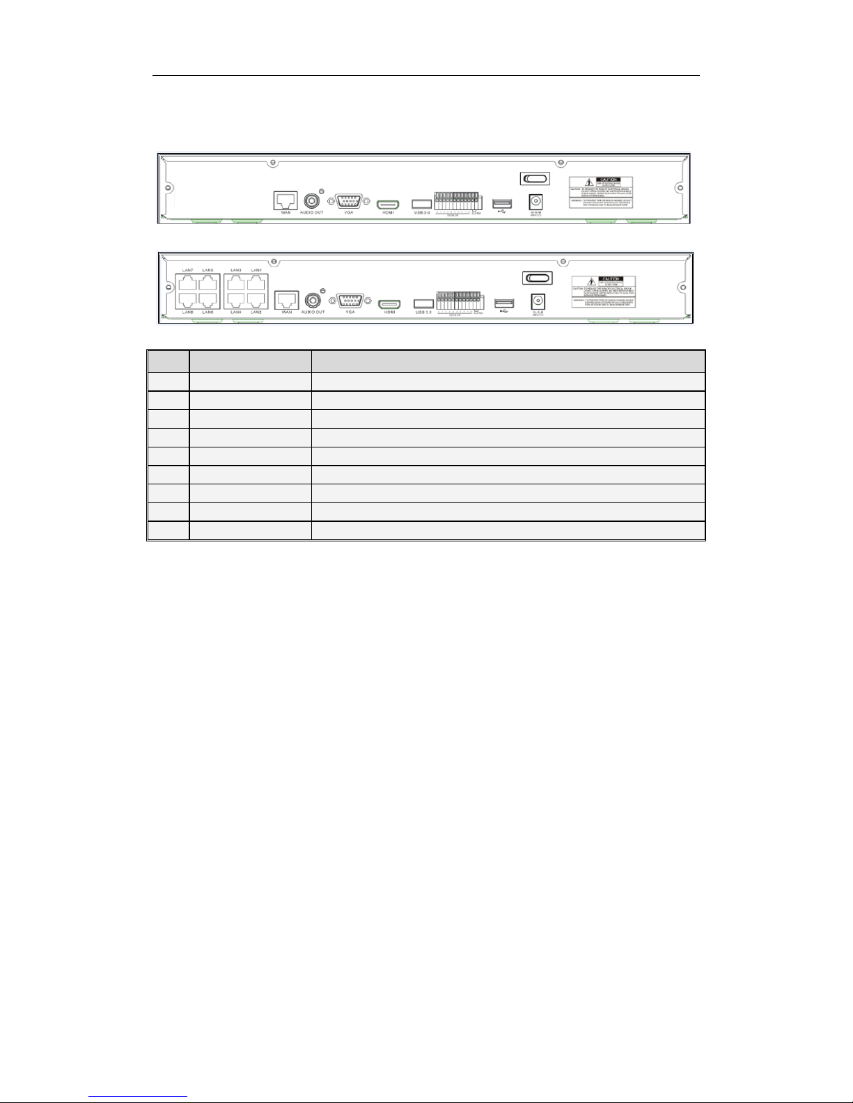
1.2 Rear Panel
NVR Rear Panel(For reference only )
Item
Physical Port
Connection Method
1
Power Port
Startup and shutdown
2
Power Switch
Connect the attached power supply
3
USB Port
Connect USB devices, such as USB mouse and USB flash disk.
4
Sensor/Alarm
Connect to sensor or alarming device
5
HDMI Port
HDMI high definition port
6
VGA Port
Connect to VGA monitor, such as PC monitor
7
AUDIO OUTPUT
Audio signal output, RCA int erf ace
8
WAN Port
Network input interface of the router/Connect to web camera.
9
LAN Port
LAN network interface, support POE, can supply power to the camera.
Table 1-2
Page 8
USER MANUAL
3
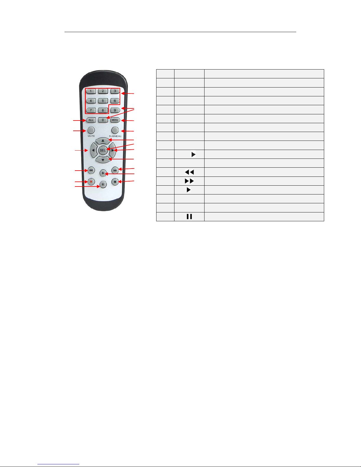
1.3 Remote Controller (For reference only)
Table 2-3 Key functions of the remote control ler
Chapter 2 NVR Connection
2.1 HDD Installation
Caution: Please do not at t em pt t o r emov e a hard drive when the NVR is running !
HDD Instal lation:
(1) Disconnect the power, and t hen r emove screws on both sides and r ear panel and
open NVR’s upper cover.
(2) Connect HDD data cable and power cable to the main b oar d. I ns t al l t he HDD on the
bracket using screws prov ided and then connect the HDD power cable and data cable.
(3) Replace the upper cover back carefully
Note: If user requires higher performance HDD, it is strongly recommended to use hard
drive designed for surveillance.
2.2 Web Camera and Monitor Connection
Transmit signals of web camera to NVR by network cable and connect VGA port or HDMI
port for output (Refer to section 2.2 Rear Panel). Refer to Chapter 7 System Connection
Diagram.
2.3 Power Supply Connection
Please use attached pow er adapt er to con nect NV R. Before power o n, make s ure netw ork
port is well connected.
Item Key title Key function
1 1-8 Channel select 1-8; Numeric key
2
9、0
Numeric key
3 ALL Multiple display mode
4 Menu Enter into Main menu/Exit
5 Mute Mute On/off
6
Submenu
Go to submenu
7 ▲ Up arrow key, volume increase
8
SEL
Select key/Edit key
9
◄/
Left/Right key; Decrease/increase parameter value of control bar.
10 ▼ Down arrow key, Volume decrease
11
Rewind key
12
Forward key
13
Enter into record search menu / Play key
14 ● Record key
15 ■ Stop manual record; stop playing
16 Pause/Sequence key
Table 1-3
1
2
3
4
5
6
7
8
9
10
9
11
12
13
14
15
16
Page 9

USER MANUAL
4
Chapter 3 NVR Boot up
3.1 System Initialization
After connecting the pow e r cabl e o f NVR t o w all o utlet and press ing t he pow er butt on, y ou
will enter into the NVR syst em initializing screen shown as Pic t ur e3-1.
Picture3-1
Note:The illustrations in this user
manual may not match the menu
interface in your monitor exactly. All
the illustrations are for users’
reference only. If you are having
difficulty, please contact our support
team.
Page 10

USER MANUAL
5
3.2 Startup Wizard
After NVR startup is completed, the startup wizard will be displayed. If you do not want to
make any setting, you may clic k “Don't show this wi ndow next ti me” t o cancel, as shown in
Picture3-2.
Wizard setting menu includes:Homepage, Network setup, IPC setup, Record Schedule
and hard disk maintenance.
1
.Homepage and network setup. In network setup page, us er m ay set the network of
NVR.
Picture3-2 Picture3-3
2.IPC Setup Picture3-4. In this page, user may add and delete IPC; Record Schedule
Picture3-4. In this page, user m ay set recording time and sched uled recording of NVR.
Picture3-4 Picture3-5
3. HDD Picture3-6. It supports HDD formatting and ov er w r iting t ype.
Picture3-6
Page 11

USER MANUAL
6
3.3 Main Interface
Picture3.2-1
Note: When internal HDD is not connected to NVR or the HDD is not formatted, first
channel of the live screen and accompany buzzer alarm. If you want to close the buzzer
alarm, please enter into [Ev entAlarm] to set HDD loss, HDD space not enough and alar m
output to “off”.
Chapter 4 NVR Menu
Popup Menu
After finishing system initialization, click right key of mouse on preview interface or slide
the mouse to the bottom of screen to enter into Pop-up Menu. Now you could perform
parameter setting and operate on Main Menu, Multi-Pics, Auto Cruise, Record Search,
Sequence, Volume setting and St r eam switching, shown as Pictur e 4-1.
The options in the pop-up menu may be varied slightly according to different parameter
settings
. The options in the menu wi ll b e explained in detail in the followin g chapters.
Picture4-1
Page 12

USER MANUAL
7
4.1 Main Menu Guide
Display
System
Live
Output
Mainstream
Schedule
DDNS
Shutdown
Main Menu
Privacy Zone
IP Camera
Parameter
Network
Record
Alarm
Record Search
Event Search
Device
General
Users
Info
Log
Substream
Record
Email
Network
Alarm
Motion
Maintain
Advanced
Events
Record Search
HDD
Page 13
USER MANUAL
8
4.2 Main Menu
Picture 4-2
4.2.1 Parameter
4.2.1.1 Display
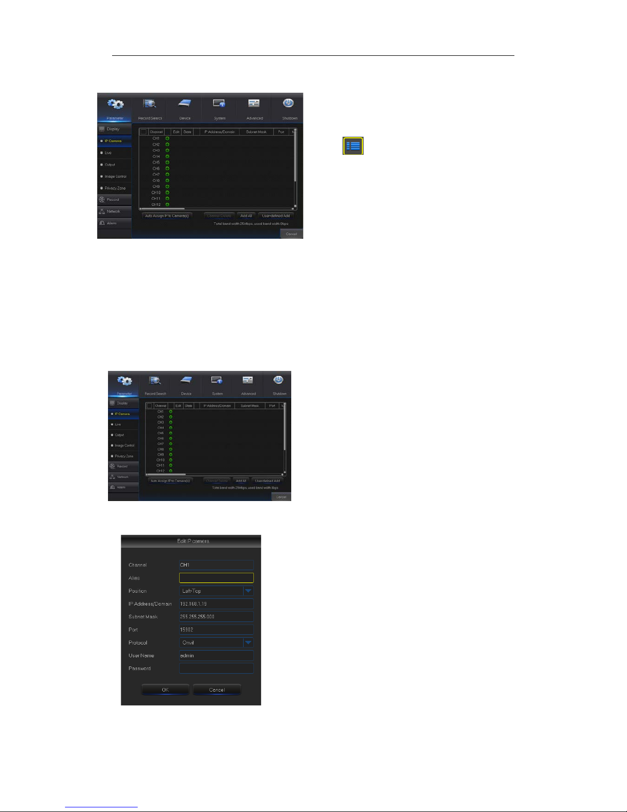
4.2.1.1.1 IP Camera
Go to “Main Menu” → “Display” → “IP Camera” to enter into the interface shown as
Picture4-3.
Picture4-3
Picture4-4
On LIVE mode, click the mouse button,
or [Menu] button on the remote controller, or
click [ ] icon on the toolbar to enter the
main menu screen, as shown in Pict ur e 4-2.
If system interface is locked, refer to
section 4.3 to unlock by inputt ing p as sword.
In Main Menu mode, you can make
settings for Parameter, Record Search,
Device, System, Advanced and S hut dow n.
Channel:IPC camera channel
Edit
:
Modify the name and location of channels,
change other IPC or protocols, etc., as shown in
Picture 4-4.
State
:
Display IPC o n-line state
IP address
:
Modify IP address of IPC camera.
IP Address/Domain
: IP address of the IPC
connected of the channel
Subnet Mask:IPC camera subnet ma sk
Port:Connection port number of the currently set
IPC.
Manufacturer:Manufacturer for different IPC
Device type:Add IPC wit h different protocols.
Protocol: The selected access protoc ol for IPC to
connect to NVR
MAC Address:Physical address for device
Software:Display current v er sion of IP C.
Page 14
USER MANUAL
9
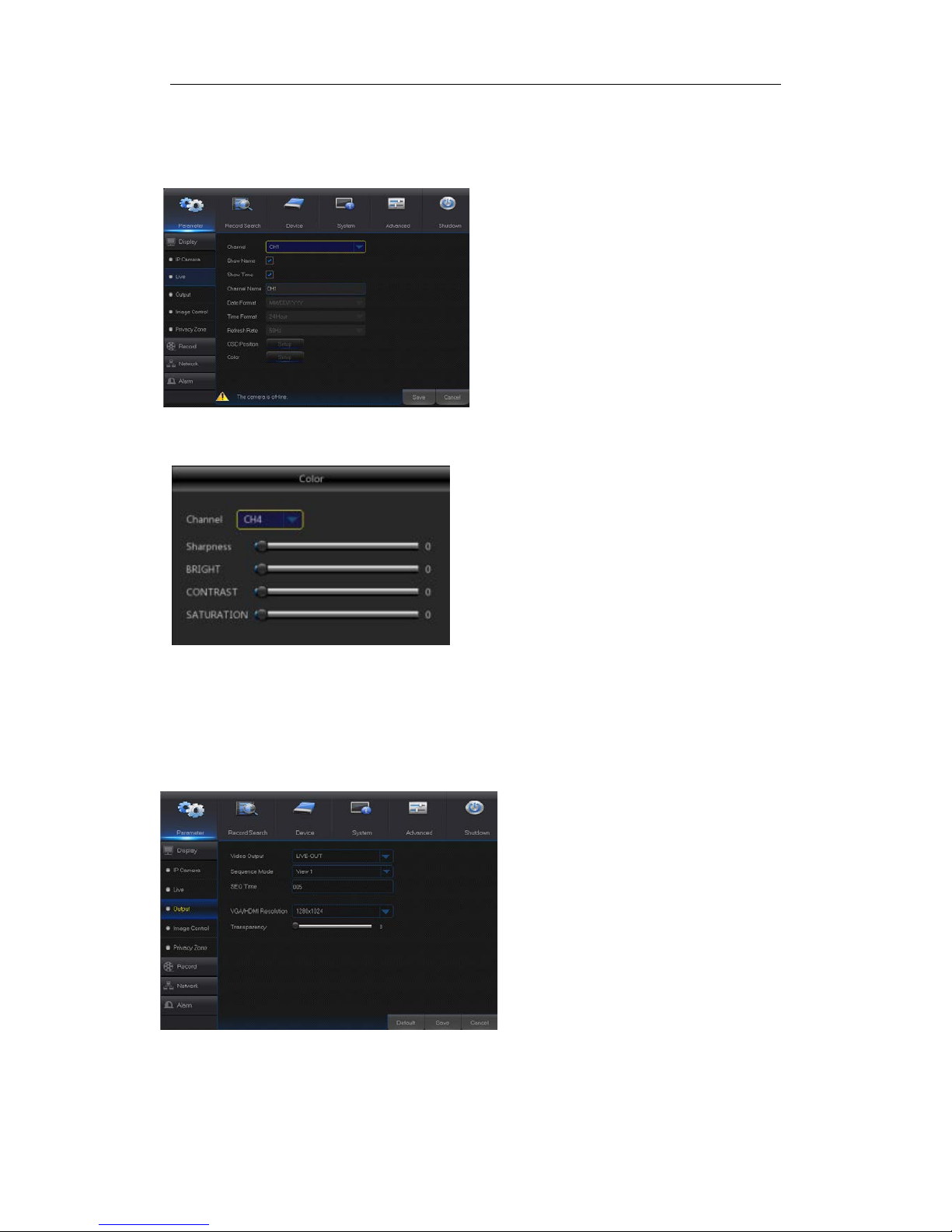
4.2.1.1.2 Live
Go to “Main Menu” → “Display” → “Live” to enter into the interface shown as Picture4-5.
Picture4-5
Picture4-6
4.2.1.1.3 Output
Go to “Main Menu” → “Display” → “Output” to enter into the interface shown as
Picture4-7
Picture4-7
Video Output
:
Live Output
SEQ Mode
:
Set sequence mode
SEQ Dwell Time
:
Sequence dwell time is
set 5 seconds by default. User may set it
as required.
VGA/HDMI Resolution
:
VGA output or
HDMI output. Including 1024×768 ,
1280×1024 , 1440×900 , 1280×720 ,
1920×1080,1680×1050,1600×1200,1900
×1200
2560×1440,3840×2160
Transparency
:
Set the transparency of
the menu in the range of 0—128.
Channel:Select channel number .
Show Time:Tick the checkbox to display time.
Channel Name:Name marked on IPC
Date Format:Set date format such as m/d/y or
y/m/d
Time Format:12 hour or 24 hour
OSD Position :Freely set the position of IPC
name and time
Color:Adjust the chro m a, brightness, contrast
and saturation of the IPC of the channel.
Refer to Picture 4-6
Page 15
USER MANUAL
10
4.2.1.1.4 Privacy Zone
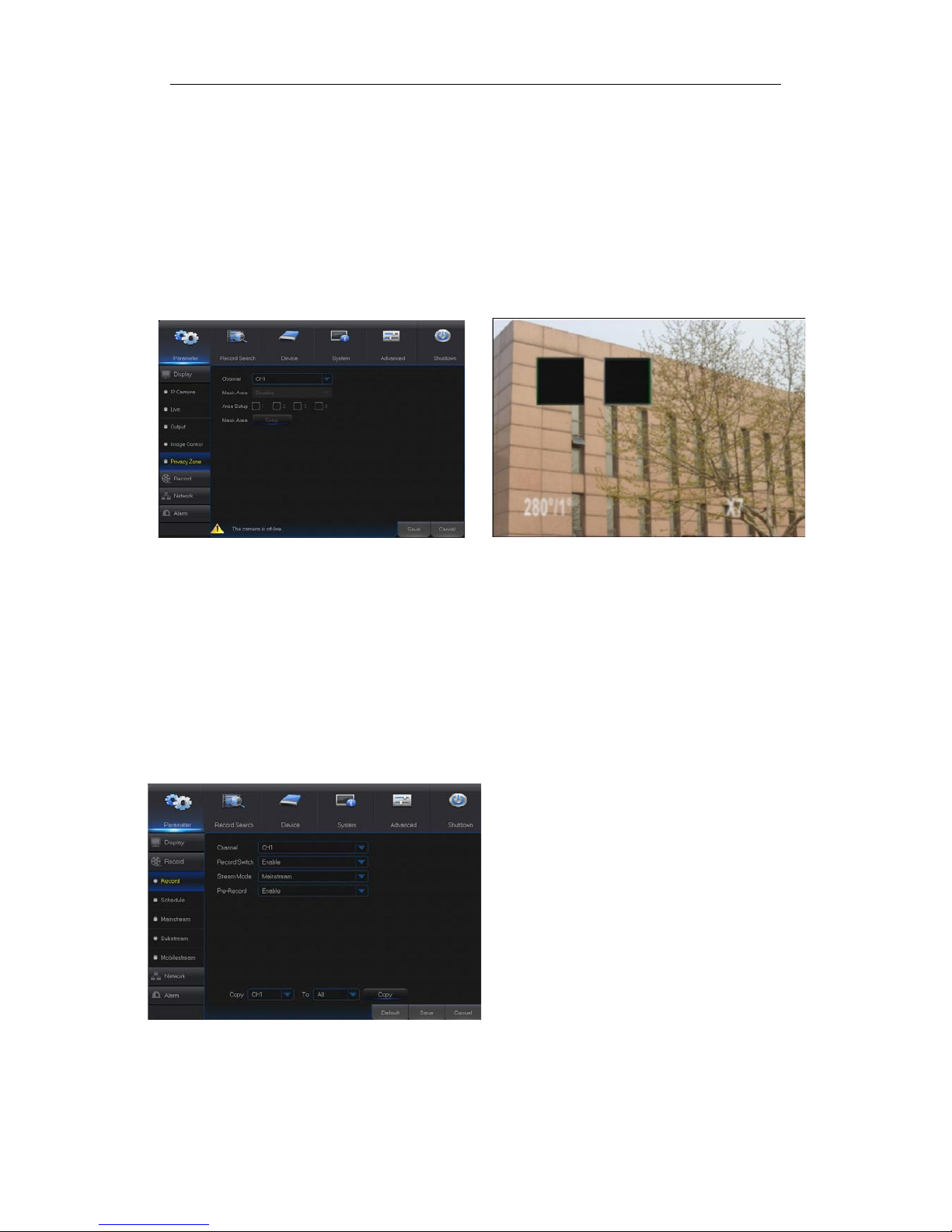
Privacy Zone is for setting some invisible parts in the selected channel, as shown in
Picture4-8 and Picture4-9.
1. Select the number of th e zone to be set (maximu m 4 zones can be set for single channel)
2. Click “Setup” to adjust the position of the zone.
3. After finish setting, right click the mouse to return to the “Priv ac y Zone” page.
4. Click “Save” to save the setting.
Picture4-8 Picture4-9
4.2.1.2 Record
4.2.1.2.1 Record
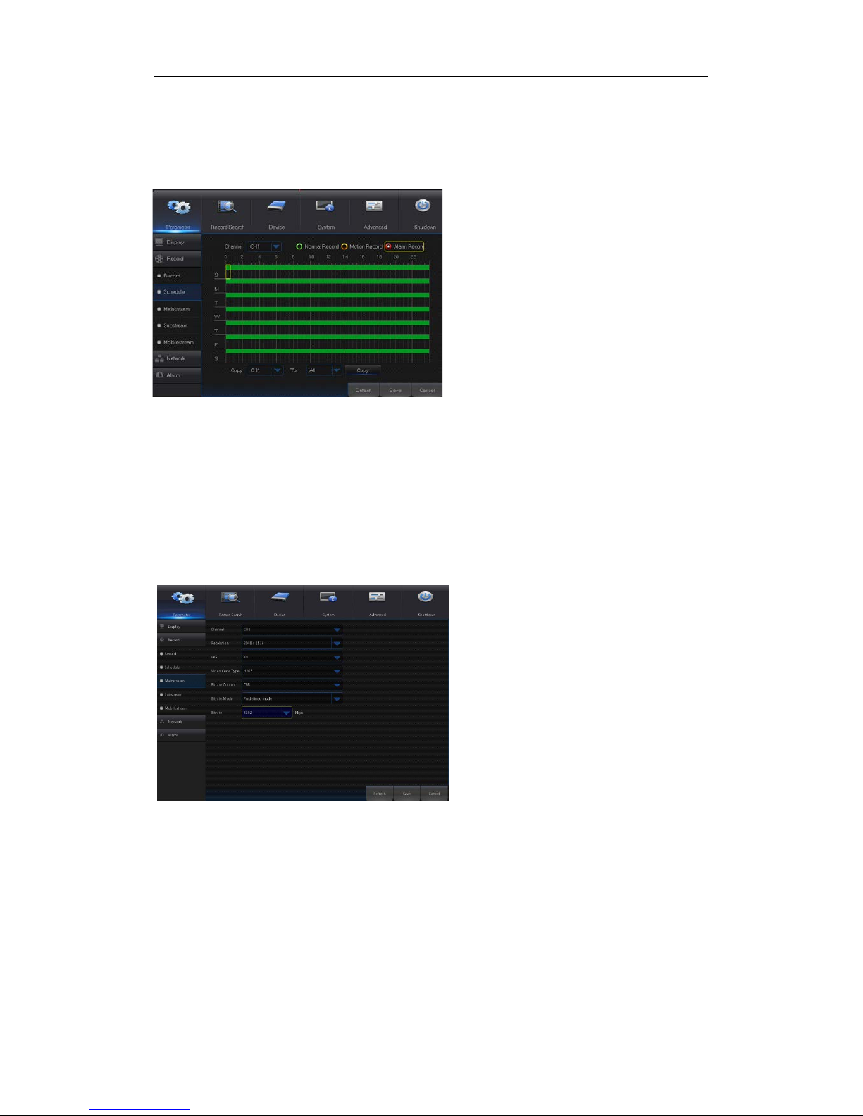
Go to “Main Menu” → “Record” → “Record” to enter into the interface shown a s Picture4-10.
Picture4-10
Channel:Set the desired channel in the
drop-down menu
Record
:
Set up the record
status(Enable/Disable) of each channel.
Stream Mode
: Select Mainstream or
Substream.
Prerecord: “Enable”
status supports
pre-record for motion detection record or
I/O trigger record.
Page 16
USER MANUAL
11
4.2.1.2.2 Schedule
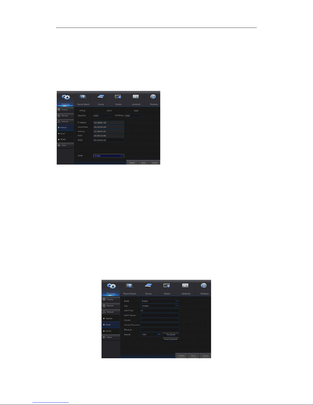
Go to “Main Menu” → “Record” → “Schedule” to enter into the Schedule interface shown as
Picture4-11 and set the re cor d schedule of NVR.
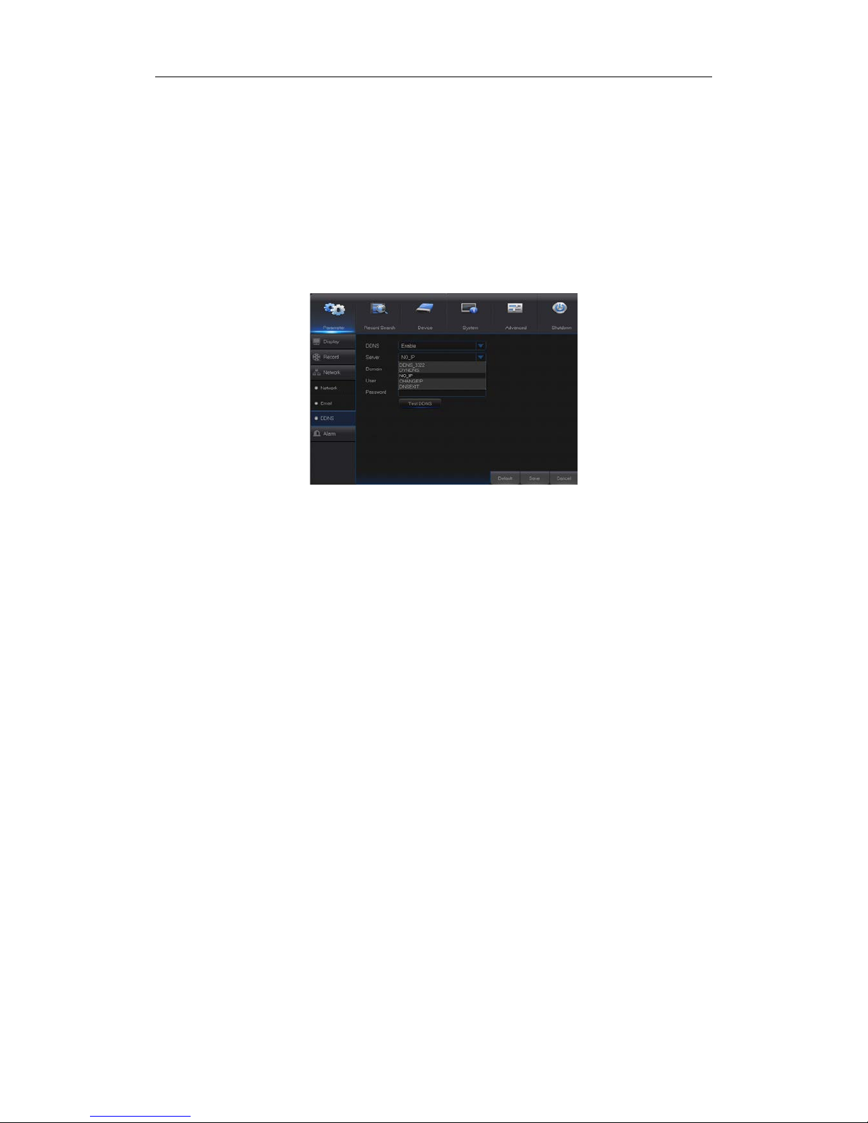
4.2.1.2.3 Mainstream/Substream
Go to “Main Menu” → “Record” → “Mainstream/Substream” to enter into the menu
interface as shown in Pictur e 4-12.
Select the channel and the date t o be set . One
week’s schedule can be set.
The record schedule of the cur rent channel can
be copied to any other channel or all channels.
Note:
1.
In the Record menu and Record Search
menu, No Color stands for no record;
2. “Green” stands for normal record and
“yellow” stands for motion record
3. “Red” stands for alarm record,
Picture 4-12
Picture4-11
Mainstream and substream are the two
video stream of IPC. Mainstream is mostly
used for recording and the substream is
mostly used for remote netw or k mon itor i ng.
Channel
:
Select a channel
Resolution
: Set IPC resolution as
required
FPS:Min 1 and max 30
code type: H.264 and H.265
Bite rate control:
Dynamic and Statics
Bitrate Mode:Preview Mode and User-
defined Mode
Bitrate
:
Set IPC bitrate
Page 17
USER MANUAL
12
4.2.1.3 Network
4.2.1.3.1 Network
Go to “Main Menu” → “Parameter” → “Network” to enter into t he interface shown as Picture
4-13.
Select a kind of network connection (PPPOE, DHCP, Static) and set Port, then user may
remotely control the monitoring, recording, playback or backup of NVR through network,
as shown in Picture 4-13.
Picture 4-13
4.2.1.3.2 E-mail
Go to “Main Menu” → “Parameter” → “Network” → “Email” to enter i nto the menu interfac e.
Receive or Send NVR alarm Email and set parameters like Email address, SSL, Email
Enable, Interval and Email Schedule. The related parameter setting should be consistent
with NVR local setting.
Picture 4-14
For PPPoe, Static and DHCP, after setting IP
address of NVR, the extranet port sh
all be
mapped on the router before visiting NVR
through public ne twork.
Note: Save after setting to make effective. If there
are multiple NVR in a LAN, make sure their MAC
addresses are differ ent ( Refer to System).
Take DHCP as an example. In this mode, the
router automatically assigns IP address for
NVR. After restarting NVR or DH CP server, t he
IP address obtained by NVR may be different.
As a result, user shall check IP address and
port number for each remote access of NVR.
The operation procedure i s as fo ll ow s:
1. Select DHCP, click S ave and refresh NVR.
Input Client Port and HTTP Port (the two
values must not be the same).
2. Set obtained IP address of NVR and the
mapping port. Refer to section4.2.4.2.
3. Remotely visit NVR by IP address:
http://Public network IP: Web port number
(such as 00080)
http:// Intranet IP: Web port number(such as
00080)( Only available in the same LAN)
Page 18
USER MANUAL
13
4.2.1.3.3 DDNS
Go to “M ain Menu” → “Parameter” → “Network” → “DDNS” to enter into the menu interface.
User may set DDNS in any one of the above network connection after applying dynamic
domain service. User may remotely access NVR through domain by using browser in the
form of http://applied domain: mapped Web port number . When using DDNS domain name
to access NVR, user shall confirm that the port can be nor mally connect ed to curr ent IP on
the public network and the settings for server address/host name/user/password/setting
should be consistent with NV R local setting. See Picture 4-15.
Picture 4-15
Page 19

USER MANUAL
14
4.2.1.4 Alarm
Go to “Main Menu” → “Parameter“ → “Alarm” → “Motion” to enter into the interface show n
as picture 4-16-1.
Picture 4-16-1
4.2.1.4.1 Motion
Picture 4-16-2
Area
:Click it to enter into the interface shown as Pictur e 4-16-2 t o set t he motion
detection area to be monitored intensively.
A single channel is divided into 15 x 12(PAL)or 15 x 10(NTSC)configurable
grids. The red grids indic a te t hat the motio n detect io n in the area is en abled, white
semitransparent ones indicates that the motion detection in the area is disabled.
After setting is completed, right click the mouse button to return and click Save to
make the parameter setting effective.
Record Channel
:When object motion is detect ed, the record ch annel sett ing wil l
be activated.
Channel: Enable or disable Motion function.
Sensitivity: Support 1-8 level, 8 is the highest level.
Buzzer:
When detecting object moving, buzzer
makes alarms (disable, 10 seconds, 20 seconds, 40
seconds and 60 seconds).
Alarm Out: Connect to the a la rm switc h of t he a larm
apparatus.
Show Message: Messages will be displayed on the
screen when moving object is detected and alarms
are made.
Send Email: When moving object is detected, send
Email to the specified Email address.
Full Screen:
When moving object is detected,
messages will be displayed in full screen.
Latch Time: When moving object is detected, the
alarm time can be set as 10 seconds, 20 seconds,
40 seconds and 60 seconds.
Post Recording:
After the alarm finishes, the
duration time of the a larm re cording can be set as 30
seconds, 1 minute, 2 minutes and 5 minutes.
Page 20
USER MANUAL
15
4.2.1.4.2 Alarm
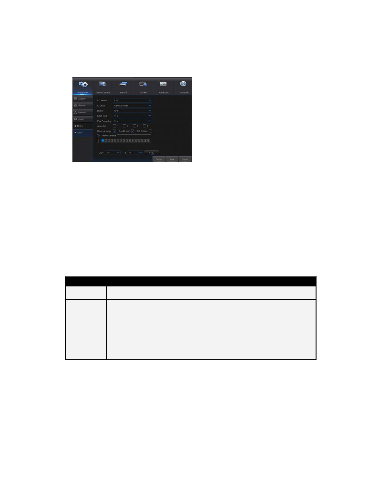
Go to “Main Menu” → “Alarm” → “Alarm” to enter into the interface shown as Picture 4-
17.
Picture 4-17
Show Mes sage: Display the alarm messages on the screen when motion alarm is
detected.
Send Email: Set to send email to specified email when motion alarm is detected.
Full Screen Alarm: W hen the motion is detected, the corresponding channel will be
switched to the full screen mod e.
Latch time: you can set how long the buzz er will sound when ob ject move is det ected
by external sensor(10s, 20s, 40s , 60s)
Post Recording: You can set how long alarm record will last when alarm ends (30s,
1minutes, 2minutes, 5minutes).
Record Channel: The record channel will be activated when the object move is
detected.
Copy: Allow you copy current channel parameters to any other channel (setting of
record channel cannot be copi ed) .
Alarm Type Functions & Descriptions
Video Loss
When NVR fa ils to rec eive vi deo signa ls due t o some pr oblems (camera d amage, line
dropout or damage, power failure), the alarm will appear.
Motion
Detection
When IP camera detects object moving, alarm will be activated. Sensitivity is subject to
the actual application environment test. Sensitivity
is adjusted according to the
sensitivity of moving object detection and parameters are modified by combining the
area setting.
I/O Status
Communicate with alarm device through I/O port. Alarm signals sent by IR sensor or
other devices will be transformed to the system recognized signal and activate relevant
channel to record or control the device output.
HDD Status
Alarm will appear when HDD does not work due to damage, power failure, HDD autooverwrite off and insufficient space.
Table 2-4
It is the alarm m anagement and setti ng of the machine . User
may set alarms under diff erent status in the int erface. Please
refer to Table 2-4
Alarm in: User may set four groups of alarm input.
Alarm Type: There are three kinds of status, i.e.
Always ON, Always OFF, and OFF. Always ON: When
the trigger is on, I/O alar m appears; Always OFF: When
the trigger is off, I/O alarm appears; OFF: Do not
receive I/O alarm from trigger.
Buzzer Time: You can set how long the buzzer will
sound w hen motion is detected (off, 10s, 20s, 40s, 60s)
Alarm out: Connect the external alarm switch.
Page 21
USER MANUAL
16
4.2.2 Record Search
4.2.2.1 Record Search
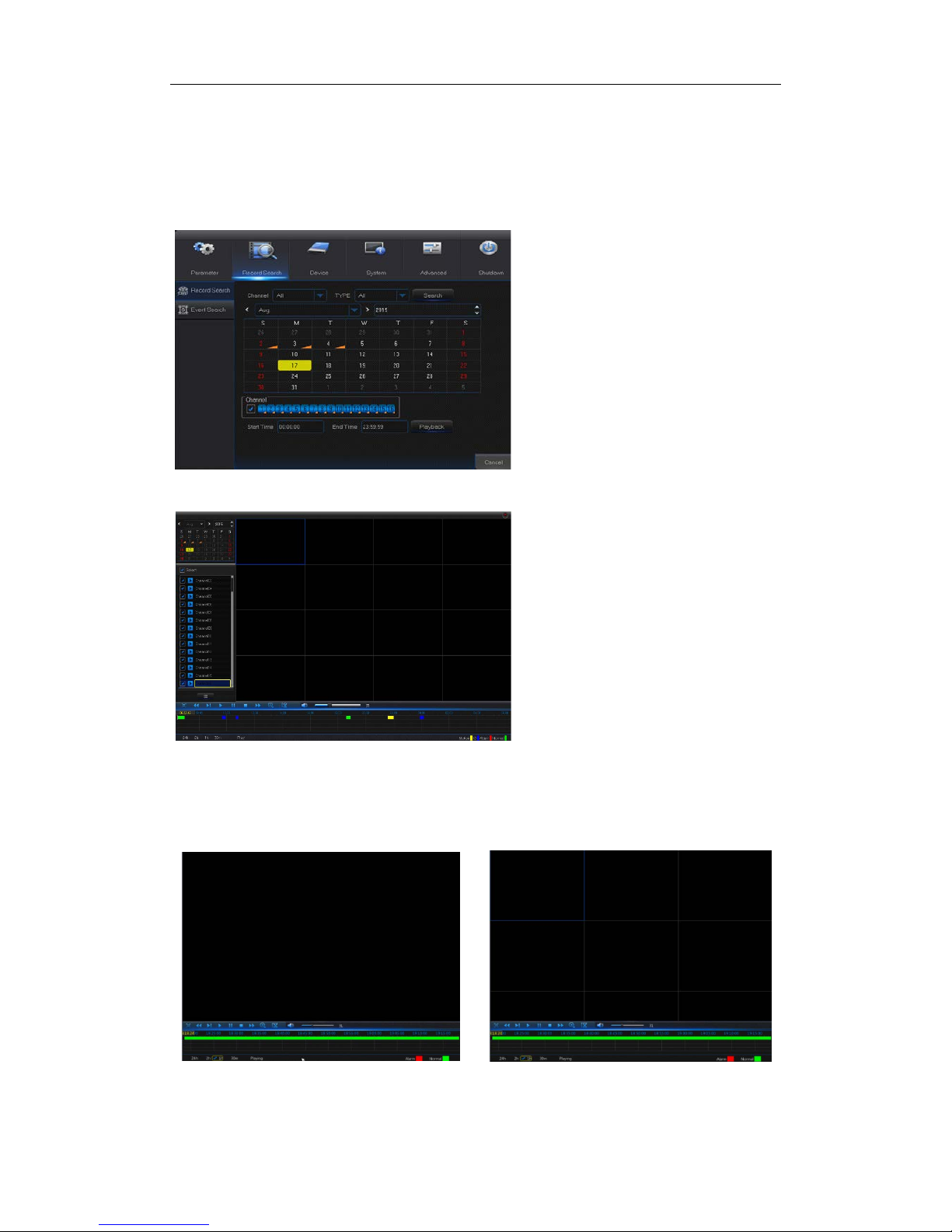
Go to “Main Search” → “Record Search” to enter into the interface shown as Picture 4-18
Picture 4-18
Picture 4-19
Time Axis setup, file clip and zoom in/out
1) The NVR supports the processing control bar function when pl aying back record files
Picture 4-20-1 Picture 4-20-2
Time Axis zoom: Defa ult v alue i s 24hour s. Allow us e r t o select 2 hour s, 1 ho ur, 30 minut es
or user-defined.
Channel: Select th e channel you w ant to sear ch.
Type: Select the type the playback re cord. There
are two options, i.e. Normal and Alarm.
Start Time/End Time: Select the specific period
of time. The default setting is from 0:00 to 24:00.
Playback Channel: Click a date and select
corresponding channel in Playback Channel.
The selected channels sha ll not be more t han 16,
as shown in Picture 4-19.
Playback: Select the desired year and month
and click “Search”. If there are any records, a
yellow corner mark which sho ws the recordi ng at
specific date will app ear at the down-right corner
of the date sheet. Select the date checkbox and
select playback channel and click Playback to
enter into the interface.
Playback interface: You can use the Playback
Control bar to operate t he Fa st F orward (X2, X4,
X8 and X16), Rewind (X 2, X4, X8 and X16), Slow
play (1/2, 1/4 and 1/8 speed), Play,
Pause/Frame. You can click or drag the volume
control bar to adjust volume. When playback
ends, NVR will remain in the playback interface,
as shown in Picture 4-19.
Page 22
USER MANUAL
17
Detailed operation
:
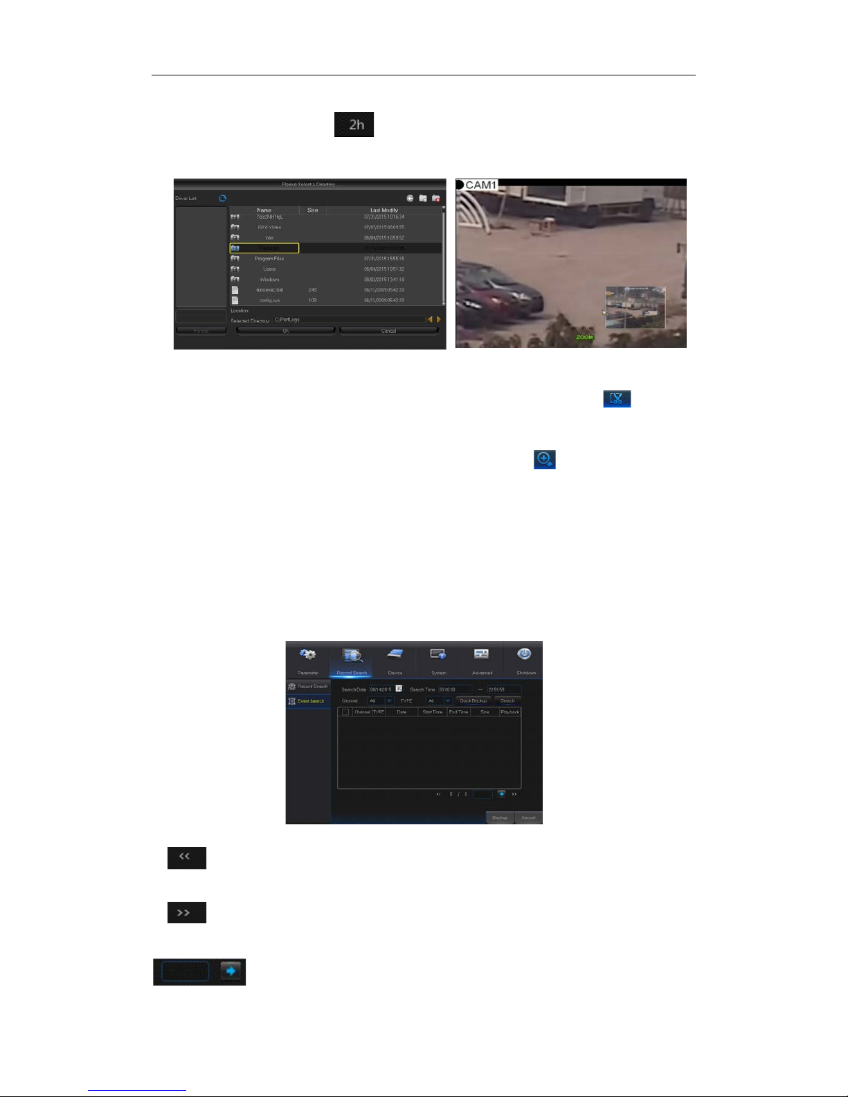
Fixed time axis: If you select [ ] option, that means the processing control bar cover
two-hours video content. The t ime range re fers to 1 hour be fore and a fter the midd le point.
2)Record clip and backup fun ct ion and playback zoom in/out func t io n.
Picture 4-21-1 Picture 4-21-2
Clip and backup: W hen it is under single channel playback, the [ ] icon will
appear in the Play Control bar shown as Picture 4-21-1. Click the icon to start video
clip function, click the icon again to end the function and pop up the dialog shown as
Picture 4-21-1. Now, you may sav e t he clipped video file.
Zoom out
:When it is under single c hanne l play ba ck, th e icon will appear in the
Play Control bar. Click the icon to zoom in certain area of the playback screen and
right click mouse to return t he Play back page.
4.2.2.2 Event Search
Go to “Main Menu” → “Re cord Searc h” → “Event Sear ch” to enter into the inter face sh own
as Picture 4-22.
In this page, user may search details by date, time, chann el and recor d ty pe. The relevant
operations are as follows:
Picture 4-22
: Next page; Click the button to go to next page when viewing events (except
the last page). When viewing the last page, click this button to display the event list in the
last page.
:Ju mp; Input the desired recor d event page in the input box an d click arrow
:Previous page; Click the button to go to previous page when viewing events
(except the first page). When viewing the first page, click this button to display the event
list in the first page.
Page 23
USER MANUAL
18
button to jump to the input page.
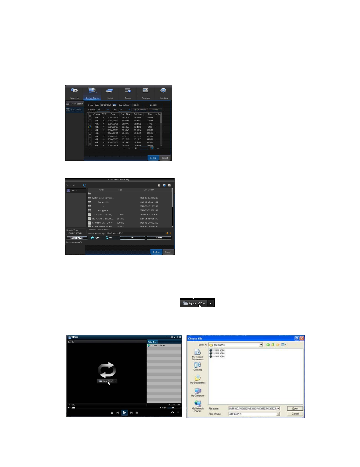
Two t ypes of backup:Quick Backup and Backup
If you want to back up a record in the detailed file list, you may t ick the checkbox at the left
of the record (“√” means it has been selected) and click “Backup” to enter into “Select
backup type” (Make sure U disk or other port able storage dev ice are connected) , as shown
in Picture 4-23.
Picture 4-23
Picture 4-24
4.2.2.3 Play Backup Files
1. Copy backup files to the computer.
2. Open playback player and cli ck “+” or“ ”. For example, if you want to
choose *.264, add backup fi le and select a file to play, as shown in Picture 4-25 and Picture
4-26.
If you want to back up with USB, sel ect USB
and click OK to start processing and you
may see the backup progress shown as
Picture 4-23.
After backup finishes, message Backup
Finishes will appear at down-right corner , as
shown in Picture 4-24.
Note: Before backup, connect devices for
backup (U flash disk or other devices with
USB interface)
Picture 4-26
Picture 4-25
Page 24
USER MANUAL
19
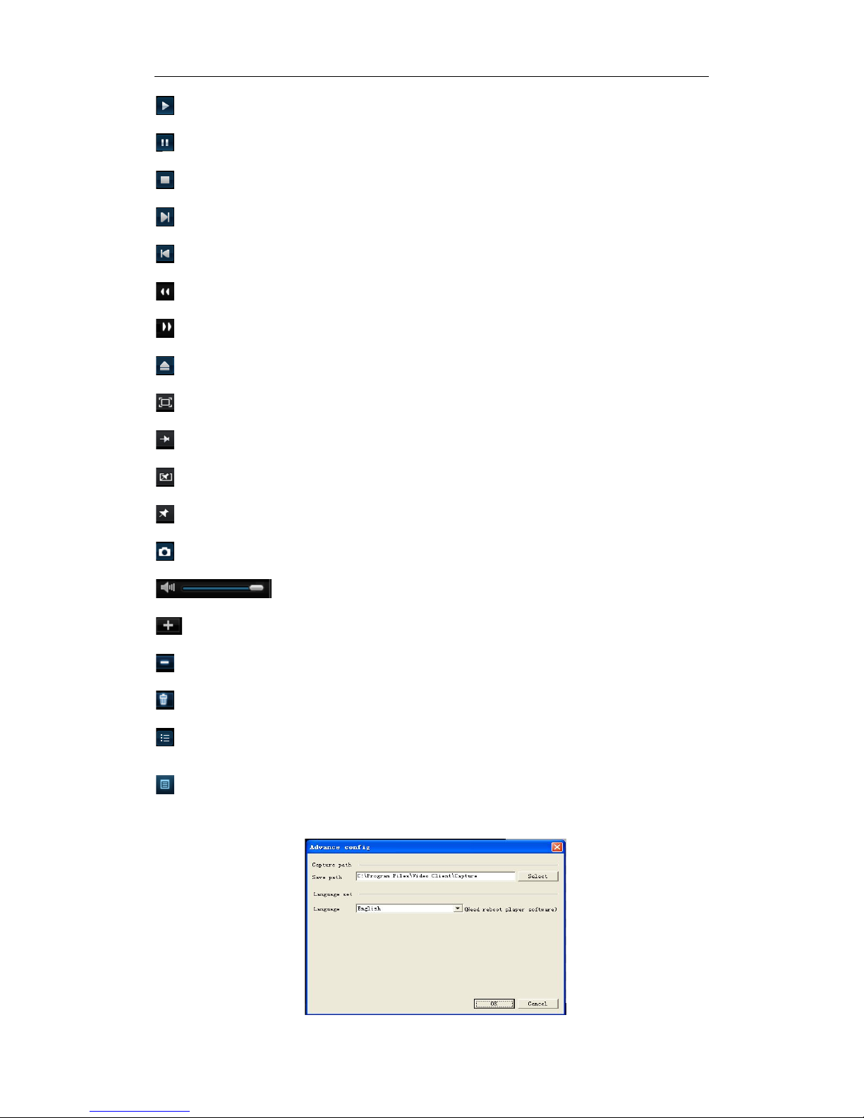
: Play: Click to play file
: Pause: Click to pause.
: Stop: Click to stop playback.
: Next: Click to play next file.
: Previous: Click to play previous f ile
:Slow Playing: click to play at 1/2,1/4,1/8,1/16 speed.
:Fast Playing: click to play at 2× , 4×,8× , 16× speed.
: Open file
: Full screen display
: Never on top
: Always on top
: On top during playing
:Screenshot: Save path: installation directory\Vide o Cl ie nt \Capture
: Adjust volume
: Add folder or file.
: Delete file in the list.
: Delete all fi les in the list.
: Expand/pack up the list.
: Adv anced configuration: Set the save path for the captured pictures and s et the display
language of player, as shown in picture 4-27.
Picture 4-27
Page 25
USER MANUAL
20
4.2.3 Device
HDD
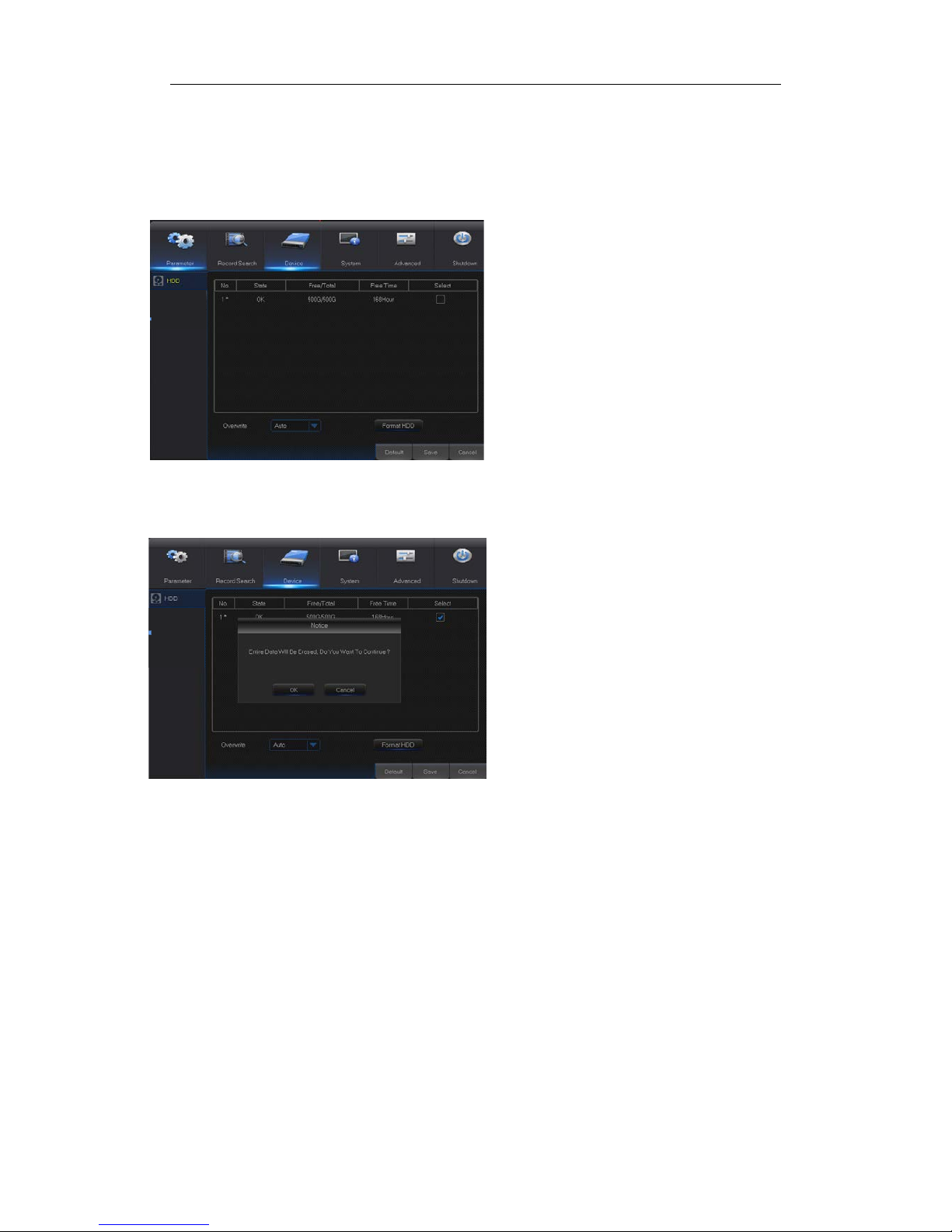
Go to “Main Menu” → “Device” → “HDD” to enter into the interface shown as Pictur e 4-28.
Picture 4-28
Picture 4-29
Note: Recording can only be performed when HDD is in “Normal” state.
When NVR is connected to a HDD, the system
will automat ically detec t if HDD is normal or not;
If HDD need to be formatted, status will be
shown as “Not formatted”. Select the HDD and
format the HDD. If the system de tects HDD is
normal state, the HDD status will be shown as
“Normal”. See Picture 4-29
No.: Number of HDD con nected to system.
Status: It shows the current status of
HDD. It w ill be available only when HDD is
“Normal”.
Free/Total Space:
Remaining or total
space of HDD
Free Time:
Remaining time for HDD
recording according to currently set
“Resolution”, “Encoding Rate” and “Frame
Rate” of image.
Auto-overwrite: When set to ENABLE,
the NVR will overwrite the oldest files on
the hard drive if hard drive space is full.
When set t o DISABLE, the NVR will st op
recording if hard drive space is full.
Overwrite time: 1 day, 3 days, 7 days, 14
days, 30 days and 90 days. It means the
longest storage time of records in HDD. If
the time is over , the records will be deleted.
For example, if the time is set as 3 hours
and the data in HDD inc lude 12, 13, 14, 15,
16, 17, 18, 19 and 20 o’clock, then data 18,
19 and 20 will be saved and data 12, 13,
14, 15, 16 and 17 will be deleted.
Format HDD: Format HDD for the first use.
Page 26
USER MANUAL
21
4.2.4 System
4.2.4.1 General
4.2.4.1.1 General
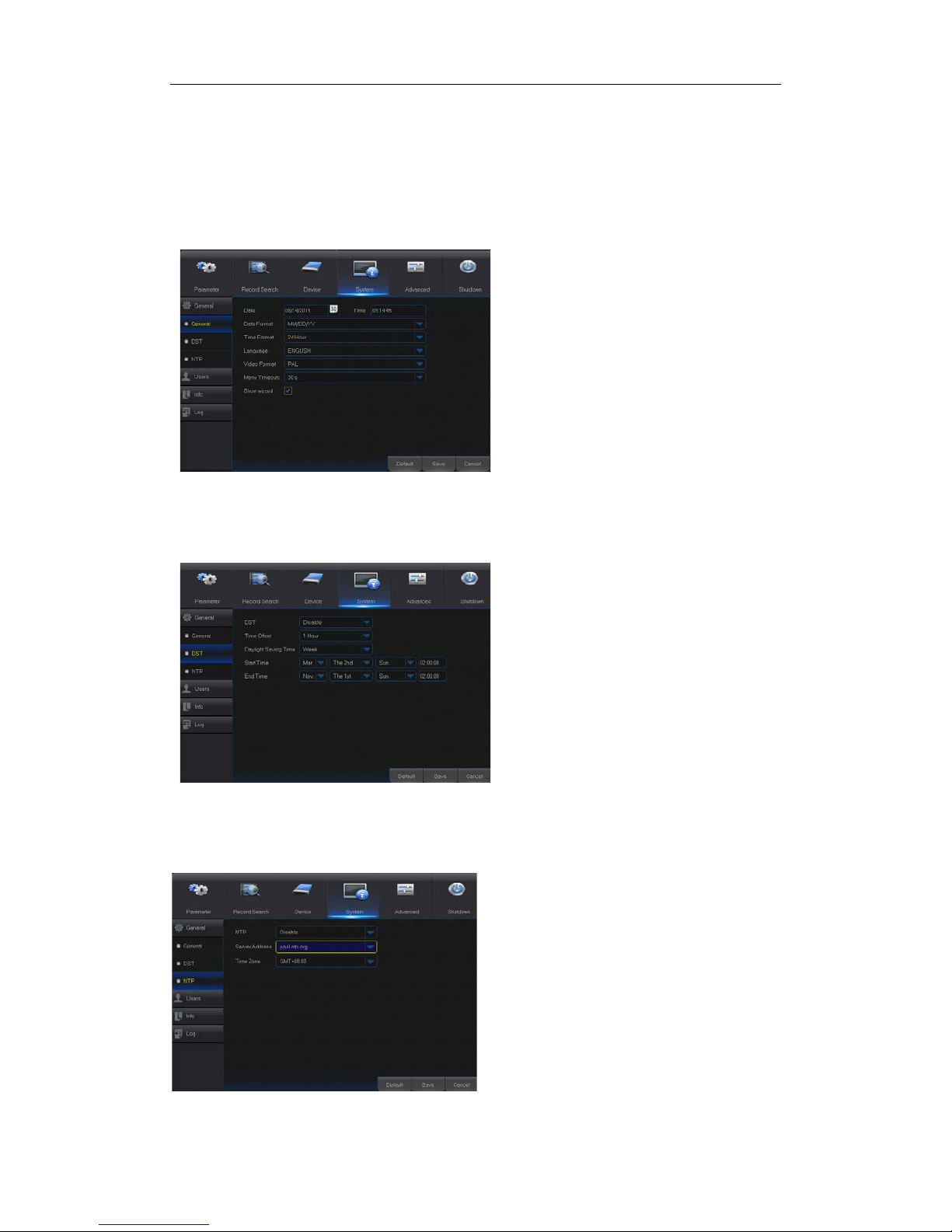
Go to “Main Menu” → “System” → “General” to enter into the interface shown as Picture
4-30.
Picture 4-30
4.2.4.1.2 DST
Go to “Main Menu” → “System” → “General” → “DST” to enter into the interface
Picture 4-31
4.2.4.1.3 NTP
Go to “Main Menu” → “System” → “General” → “NTP” to enter into the interface.
Picture 4-32
Enter into the interface shown as
Picture 4-31 to set DST, Time
Offset, Start Tim e and End Time.
NTP service: Enable/D isable NTP fu nction.
Server Address: Sel ect NTP server
(time.windows.com, time.nist.gov,
pool.ntp.org).
Time Zone: Corresponding time zones for
various nations or regions .
Update Time: Enable NTP function and
save parameters and click Update Time to
calibrate the system time.
Note: When NTP function is set to “Enable”,
system will calibrate the system time at
every 00:07:50 and every start-up.
User may set Date, Time, Date
Format, Time Format, Language,
Video Format, Menu Timeouts and
Show Wizard in this page.
Page 27
USER MANUAL
22
4.2.4.2 Users
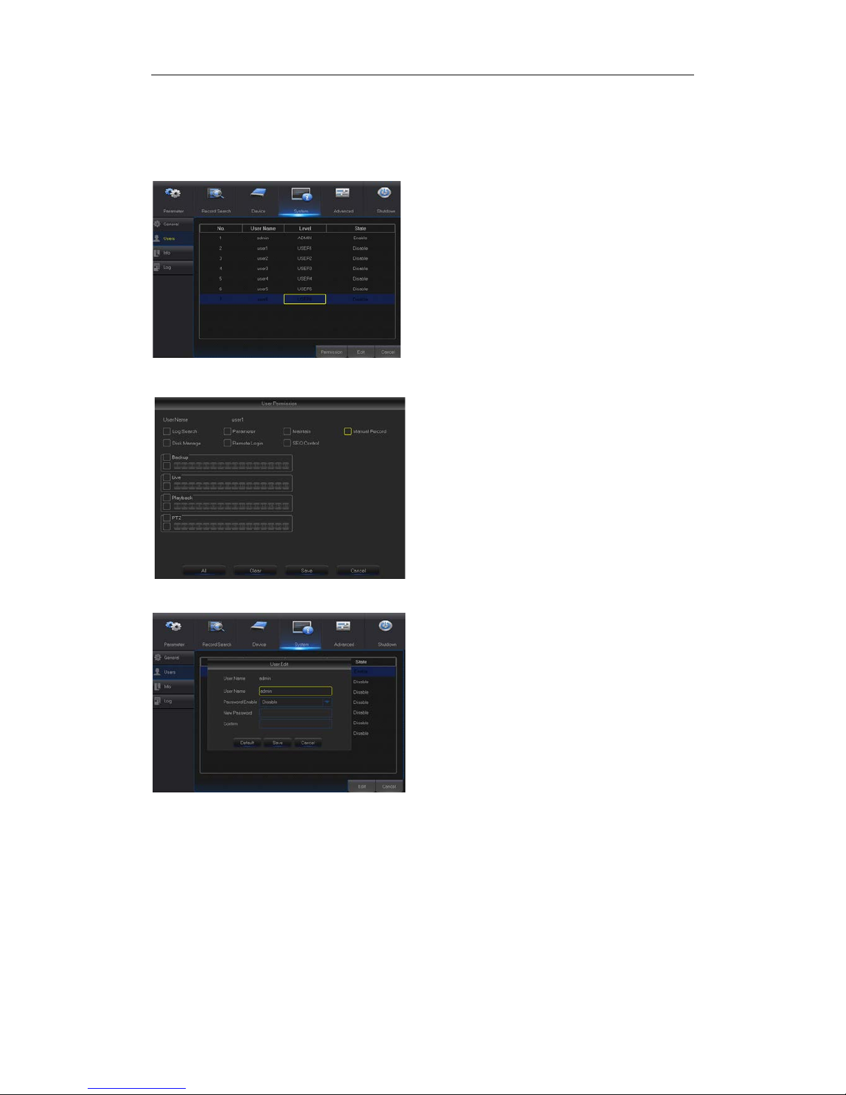
Go to “Main Men u” → “System” → “Users” to enter into the User interface shown as Picture
4-33.
Picture4-33
Picture4-34
Picture4-35
Set user password. Administer is authorize d
to set user common user’s authority.
Log Search: allow you check all the
system logs.
Parameter:
allow you set all the
parameters.
Maintain: allow you update version,
recover ex-factory v alue, device reb oot
and shut down.
Disk Management: allow you manage
and control the HDD and USB drive.
Remote Login: allow you remotely
login NVR.
SEQ Control: allow you sequence live
screens for all the channel s.
Manual Record: allow you manually
start/stop record.
Backup: Tick-
select the ENABLE
option and select channel for backup,
the user is allowed to back up the
record in the selected channel.
Live: Tick-select the ENABLE option
and select a channel and the user is
allowed to view all the live images in
the selected channel.
Playback: Tick-
select the ENABLE
option and the user is allowed to
playback the selected record in the
channel.
It supports up to seven users, includ ing one
administrator and six users. Click [Edit]
button to enter into the [User Edit] interf ace
to
input user name and password, as
shown in Picture 4-34.
User Name consists of 8 characters and
password is composed by number 0-9 with
max length of 8 numbers
Page 28
USER MANUAL
23
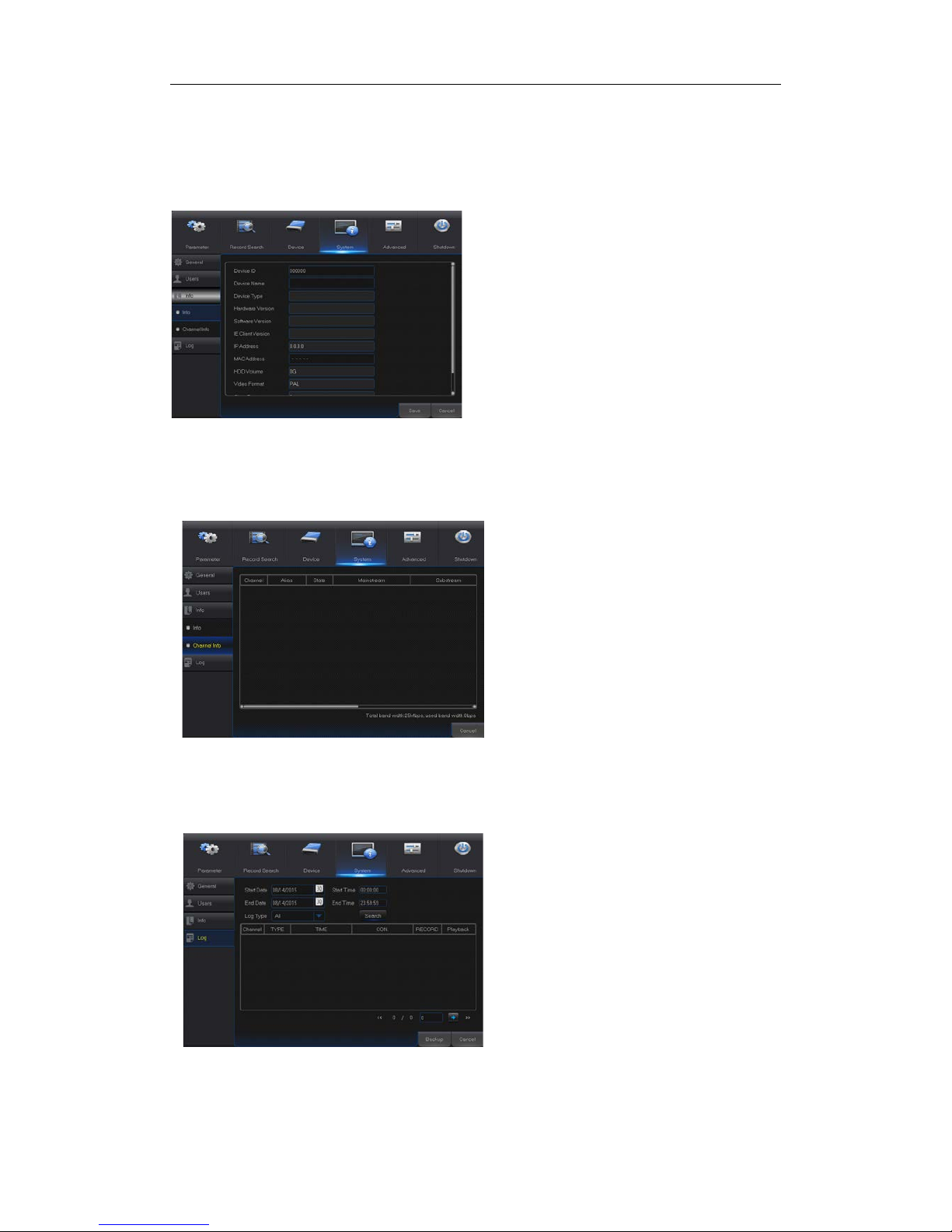
4.2.4.3 Info
4.2.4.3.1 Info
Go to “Main Menu” → “System” → “Info” to enter into the interface show n as Picture 4-36.
4.2.4.3.2 Channel Info
Go to “Main Menu” → “System” → “Info” → “Channel Info”,as shown in Pict ur e 4-37
Picture 4-37
4.2.4 Log
Go to “Main Menu” → “System” → “Log”, as shown in Picture 4-38.
Picture 4-38
User may search log information in different period of time. Click “Backup” to save all the log
information, as shown in Picture 4-38.
User can view system information, including
Device ID, Device Name, Device Type,
Hardware Version, Firmware Version, IE Client
Version, IP Address/Domain, MAC Address,
HDD Capacity, Video Format, Media Port, Web
Port, etc.
User may view the information of various
connected IPC, including state,
mainstream, substream, motion
detection, privacy zone, c ruise, etc.
Picture 4-36
Page 29
USER MANUAL
24
4.2.5 Advanced
4.2.5.1 Maintain
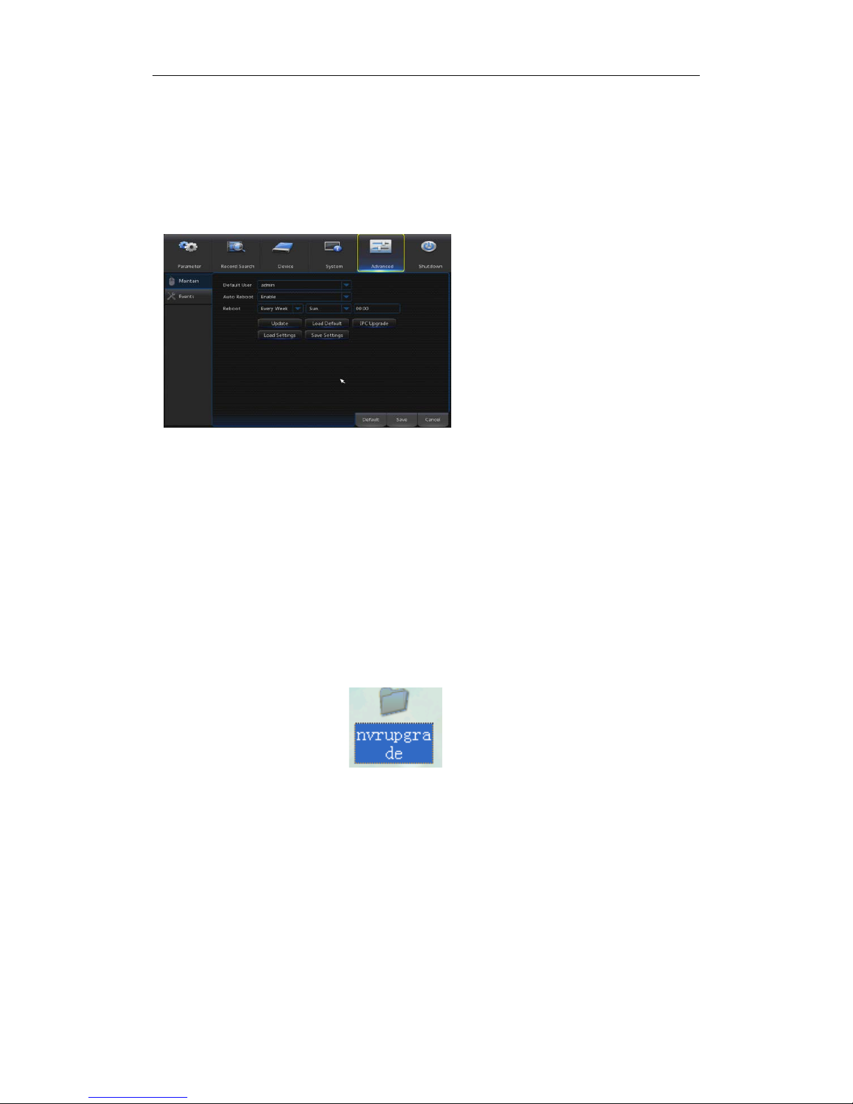
Go to “Main Menu” → “Advanced” → “Maintain” to enter into the interfa ce shown as Pictur e
4-39.
Load Default: If [Load Default] is selected, you can initialize the system to the ex-
factory default. Click “Load Default” and select items to be restored
Load Settings: Load parameters in the removable storage device to NVR.
Save Settings: Save the set parameters of user’s NVR to the removable storage
device.
IPC Upgrade
: IPC can be upgraded by the connected NVR. Decompress IPC
upgrading file and copy *.sw file t o nvrupgrade d irector y and copy t o the root directory
of U flash disk, as shown in Picture 4-40—>Insert the U flash disk into USB port of
NVR—>Select the IPC you want to upgrade—>Clic k Up gr ade t o start upgrading IPC.
Note:Do not take out the USB memory or cut off the power during upgrad ing. When
the update is done, system will be automatically restarted. After about 5 minutes, the
upgrading will be finished. It is recommended to load ex-factory default after upgrading.
The auto maintain functio n can be effective only when NV R returns bac k to Pr eview mode
with no any operation within the set aut o maintain time.
Auto Reboot: Enable the auto
maintenance function to reboot
system regularly at every
day/we
ek/month. When Auto
Reboot is enabled, NVR should be
in the main interface and no user
operation.
Upgrade: Decompress update file
package and copy the upgrade file
folder named “nvrupgrade” (see
Picture 4-40, the upgrade program
is inside) to root directory of U flash
disk; Insert the U flash disk into USB
port of NVR; Click <Upgrade> .
Picture 4-39
Picture 4-40
Page 30
USER MANUAL
25
4.2.5.1 Events
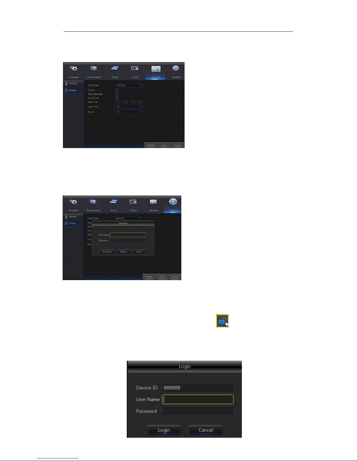
Go to “Main Menu” → “Advance” → “Events” to enter into the interface shown as Picture
4-41.
Picture4-41
4.2.6 Shutdown
Go to “Main Menu” → “Shutdown” to enter into the menu interface shown as Picture 4-42.
Shutdown or reboot funct ion requires user to login by inputting User N a me an d Passw ord.
4.3 Menu Lock
In consideration of system safety, user may click the icon on the toolbar when he
leaves away from NVR and the system interface will be locked. User has to input Device
ID, User Name and Password on the login int erface to unlock (Default: User Name: admin,
Password: blank) . The login interface is as show n in Picture 4-43.
Event Type: Support three abnormal
types: Disk Full, Disk Error and Video
Loss.
Enable: Active alarms for abnormal
situations.
Alarm Out: Enable or disable alarms
Latch Time: How long the buzz er will
sound when external sensor alarm is
detected (10s, 20s, 40s, 60s).
Show Message: You can set show
message on the screen when sensor
alarm is detected.
Buzzer: How long t
he buzzer will
sound (10s, 20s, 40s, 60s).
Send Email: Select to send Email to
specified Email address when
abnormal events appear.
Picture 4-42
Page 31

USER MANUAL
26
Picture 4-43
Note
:Administrator has all authorizat ion of menu operat ion and users hav e limitations for
authorization and have to get aut hor ization from administrator.
4.4 Split Mode
There are many display modes in video channel, including single channel display, SEQ
display and split mode.
4.5 Record Search
Click icon on the toolbar to enter into the Record Search interface to search and
playback. Refer to former sect io n 5.2.3 for specific operating method.
4.6 Mute
Click icon on the toolbar or Mute button on t he pan el or r emote cont ro ller to c ontrol
the mute of NVR.
4.7 Start Sequence
After set channel sequence time (Refer to Section 4.2.1.2), click Start Sequence icon
on the toolbar to start sequence.
Page 32
USER MANUAL
27
Chapter 5 Web Application Manager
5.1 ActiveX control download and installation
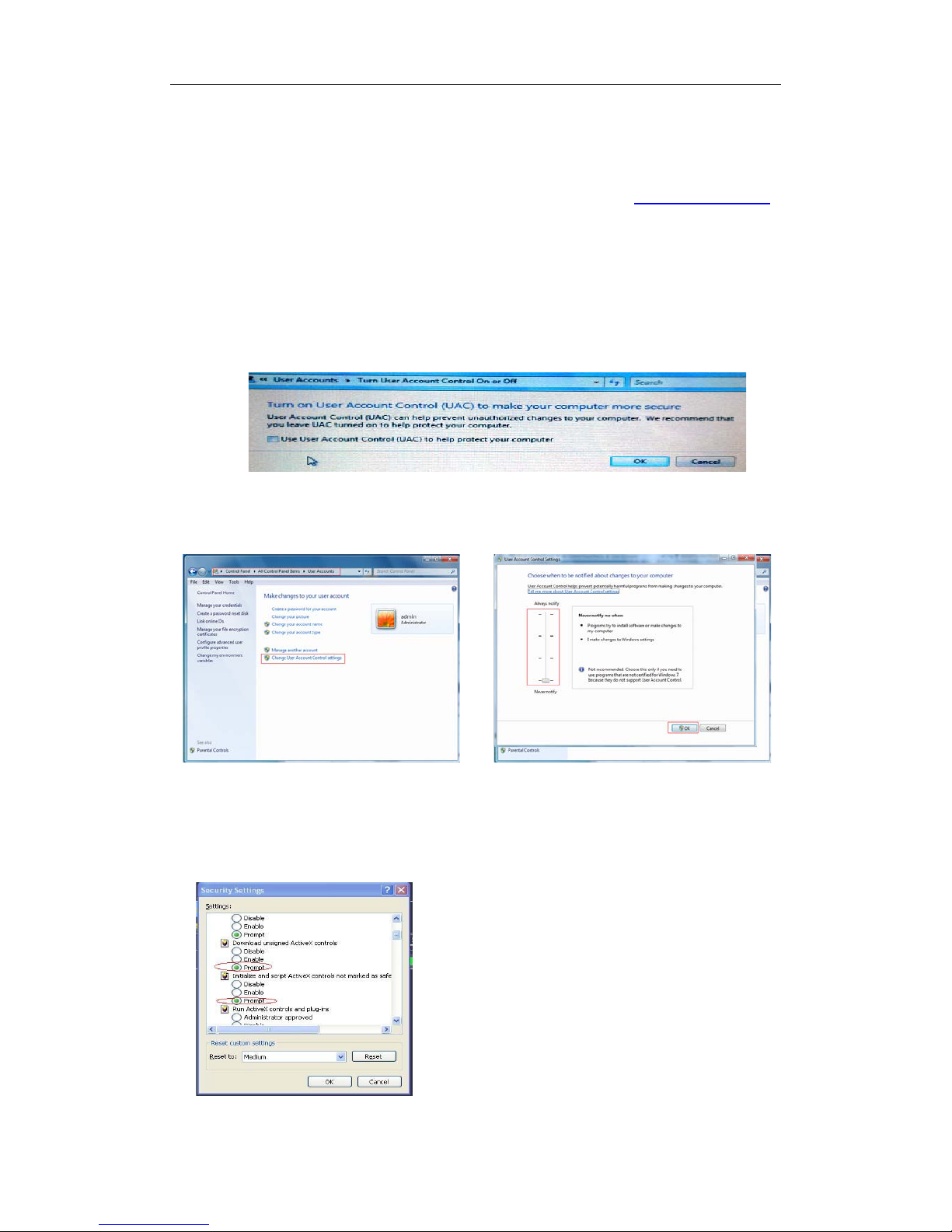
Open your web browser and input the IP address of NVR, such as: http://192.168.1.168 .
If your computer is connected to internet, it will download and install “ActiveX” plug-in
automatically. If your computer system is Windows Vista or Windows 7, you may need to
setup the user authority for r emote control, or you may be unable to backup or record.
Vista System: Start→ Setup→ Control Panel. Set user author ity in control p anel (as shown
in picture below). Remove t he Tick “√” in front of the optio n “Use UAC to help protect your
computer” and confirm OK.
Vista
WIN7:
Picture 5-1
Note: If the ActiveX control is not downloaded successfully, please check if your browser’s safety
level or firewall setting is set too high. Please open IE browser→ [Menu Bar] Tools→ Internet
options→ Security → Internet →Custom level→ Enable t he options (Refer to the Picture 5-1).
If the web application runs for the first time, please wait
for about one minute to finish dow nloading.
If you want to use the undated ActiveX control at a
computer which you have already logged in before, please
delete the original control and click [StartRun] and then
input the command characters: “regsvr32/u
HiNVROcx.ocx”. Press OK. When you log in at the next
time, new ActiveX control will be auto matically downloaded .
WIN7-1
WIN7-2
Page 33
USER MANUAL
28
5.2 Web Application Manager Login
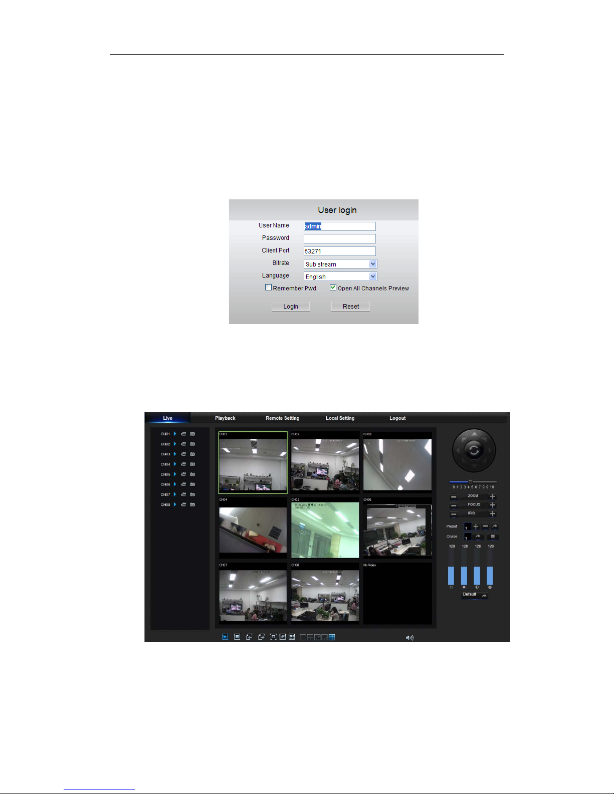
After ActiveX controls installation, please input user name and password, select Main
Stream or Sub Stream (In general, select main stream for intranet and su b stream for outer
net), and select language in the interface shown as picture 5-2. There is an option for
opening all channel preview, select it to open all live pictures. Press Login to log in client
and remotely visit NVR. The default password is admin and administer is authorized to
modify the password. Set password as per introductions of user management in system
setting.
5.3 Live Interface
Log in and enter into the live inter face to establish video link, as show n i n Picture 5-3.
Picture 5-3
Picture 5-2
Page 34
USER MANUAL
29
5.3.1 Menu Bar
Menu Bar: Live, Replay, Config ur ation, Local Setting and Logout
5.3.1.1 Live Display
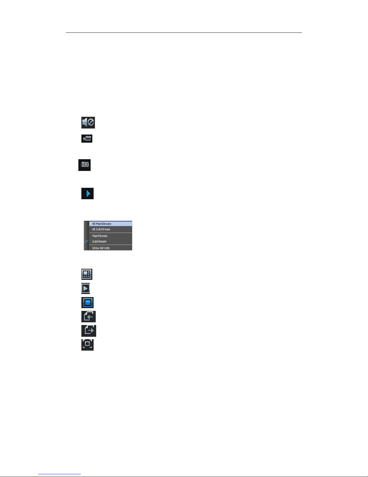
Log in the Web Application Manager, sy stem will be defaulted to enter into < Live> interface
shown as Picture 5-3. You can c lick [Play] button t o Open/close l ive images, on-spot record,
capture, and many live display m odes.
Buttons on a singl e live interface:
:Volume switch
:Record switch: the rem ote record switc h of client . Recor d will be auto matica lly
saved to a specified position on PC after the function is enabl ed.
:Snapshot: Capture the selected live image and save it to a specified position
on PC. The image is saved as *.bmp format .
: Open or close the images on Live w indow.
Or click the right key of mouse on each <Live> window to pop up channel
operation menu as shown in Pic t ur e 5-4
Picture 5-4
Show bit rate: Tick Show Bit rate to show IPC bit rate in current window.
:Switch display mode in chan nel window
:Open all the Live channels.
:Close all the Live channels
:Display previous group of ch annels
:Display next group of channels
:Click to maximize the current w indow to full screen. Right click to pop up menu
option and select Exit Full Scr een.
Page 35
USER MANUAL
30
5.3.1.2 Video Control
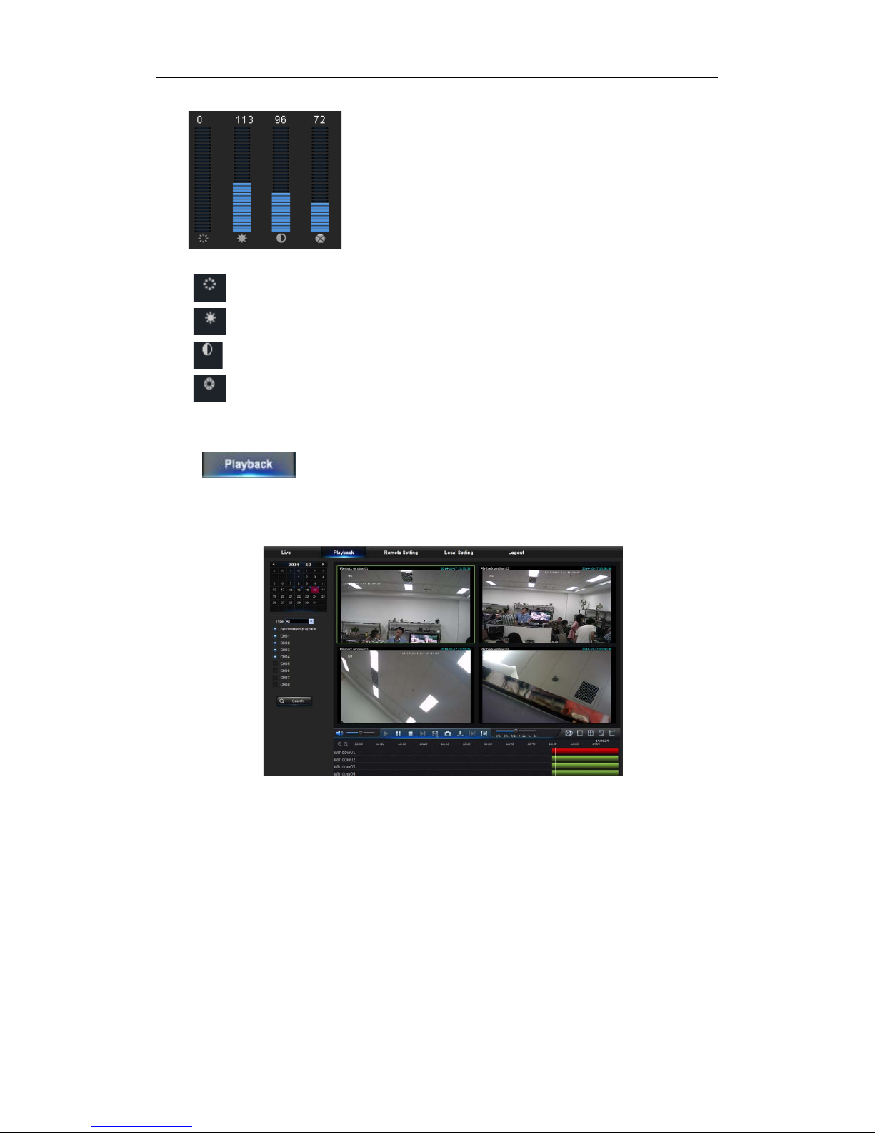
Picture 5-5
:Adjust the chromaticity of video
:Adjust the brightness of video
:Adjust the contrast of video
:Adjust the saturation of video
5.3.2 Playback
Click to enter into Playback interface to remotely v iew the records in NVR
HDD, as shown in Picture 5-6. Supports 4 channels playback.
Picture5-6
5.3.2.1 Record Search
Record playback procedure
Firstly, select the date y ou want to check and se lect 4 chan nels. Any record file s in current
channel at current date wil l be di splayed in the status bar of the interf ace.
Page 36
USER MANUAL
31
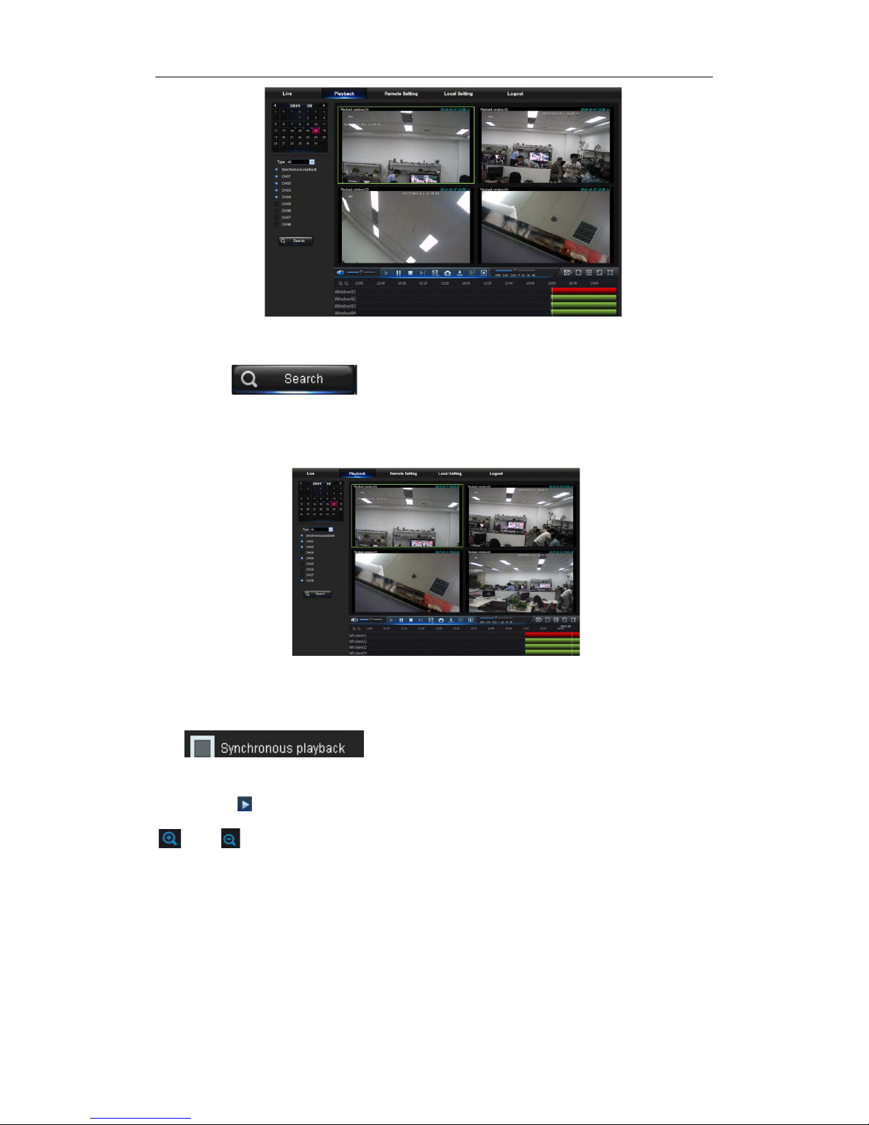
Picture 5-7
Secondly, select record type (Normal record, Alarm record and All) and channels, and
then click “ ”,and time axis panel will display specific t i me quant um,
as shown in Picture 5-7. On the time axis, red p art s tands for alar m r ecord, yel low stand s
for normal record and original par t st ands for no record during this per i od.
Picture 5-8
Before playback, choose to enable playback 4 channels synchronously. If you tick-select
“ ” , that means the selected channel will playback
synchronously; otherwis e, you could separately control the c hannels playback.
Thirdly, click to start record playback. When mouse curse is moving on the time axis,
the time point of current position will be displayed on the time axis screen. Click the icon
or to zoom in/out the time bar display ratio, as shown in Picture 5-8.
Page 37
USER MANUAL
32
5.3.2.2 Playback Control
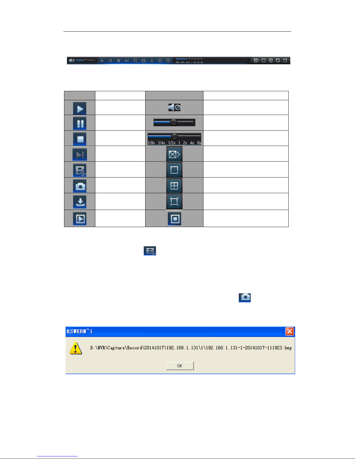
Playback control bar, as shown in pictur e 5-9.
Picture 5-9
Detailed brief description i s shown as below list
Key
Description
Key
Description
Play
Enable the volume switch
Pause
Volume adjustment bar
Stop
Slow playing 1/2,1/4.1/8, Fast
playing 1/2/4/8
By frame
Stop playing all the files
Record Clip
Single channel mode
Snap
Quad mode
Download
Full Screen
Open all the
playback channels
Stop playing all the playback
Record file clip
After opening playback, click icon to clip the selected file; and click again to stop
the clip function. Then p layback cli p is successf ully done. R ecord cl ip file will be sav ed as
*.264 format.
Snapshot functi on
Move the mouse curse to the channel you want to ca pture, and click [ ] icon to capture
the live images remotely. After capturing the images successfully, a path prompt box will
be popped up, as shown in Picture 5-10.
Picture 5-10
The captured file will be saved as .bmp format.
Table 5-1
Page 38
USER MANUAL
33
Record file do wnl oad
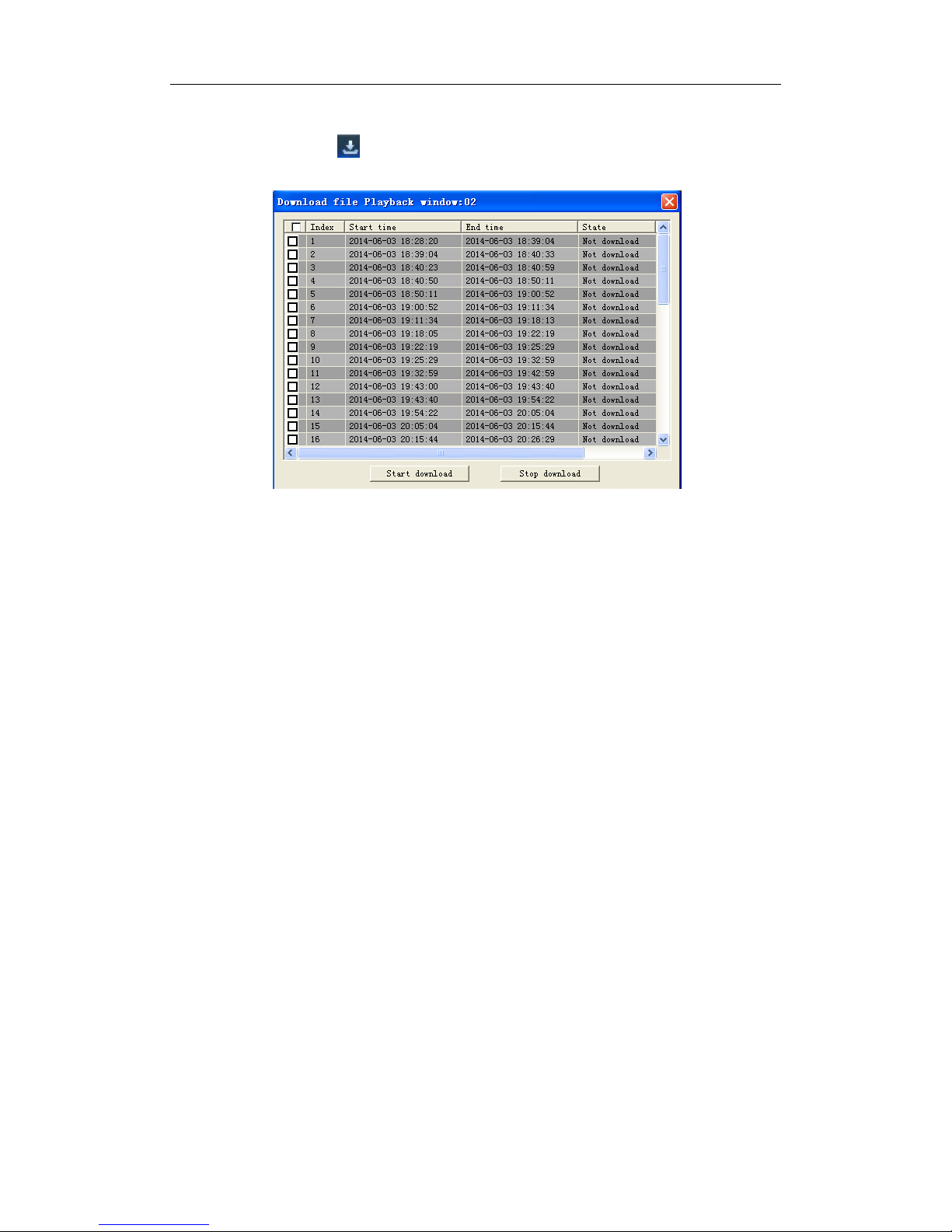
Click download icon “ ” on the control bar to display all the matched record file
according to the search cond itions of channels, as shown in pictur e 5-11.
Picture 5-11
Tick-select the record file you want to download and click [Start download] .System will
download the record file in sequence and save to local PC. The downloading file will be
displayed in percentage form. After downloading finishes, “Complete” will be displayed on
the status bar .
5.3.3 Parameter Setting
Click Parameter Setting to ent er into the interface shown as Picture 5-12, including Disp lay ,
Record, Network, Alarm, Device, System and Advance.
Page 39
USER MANUAL
34
5.3.3.1 Display
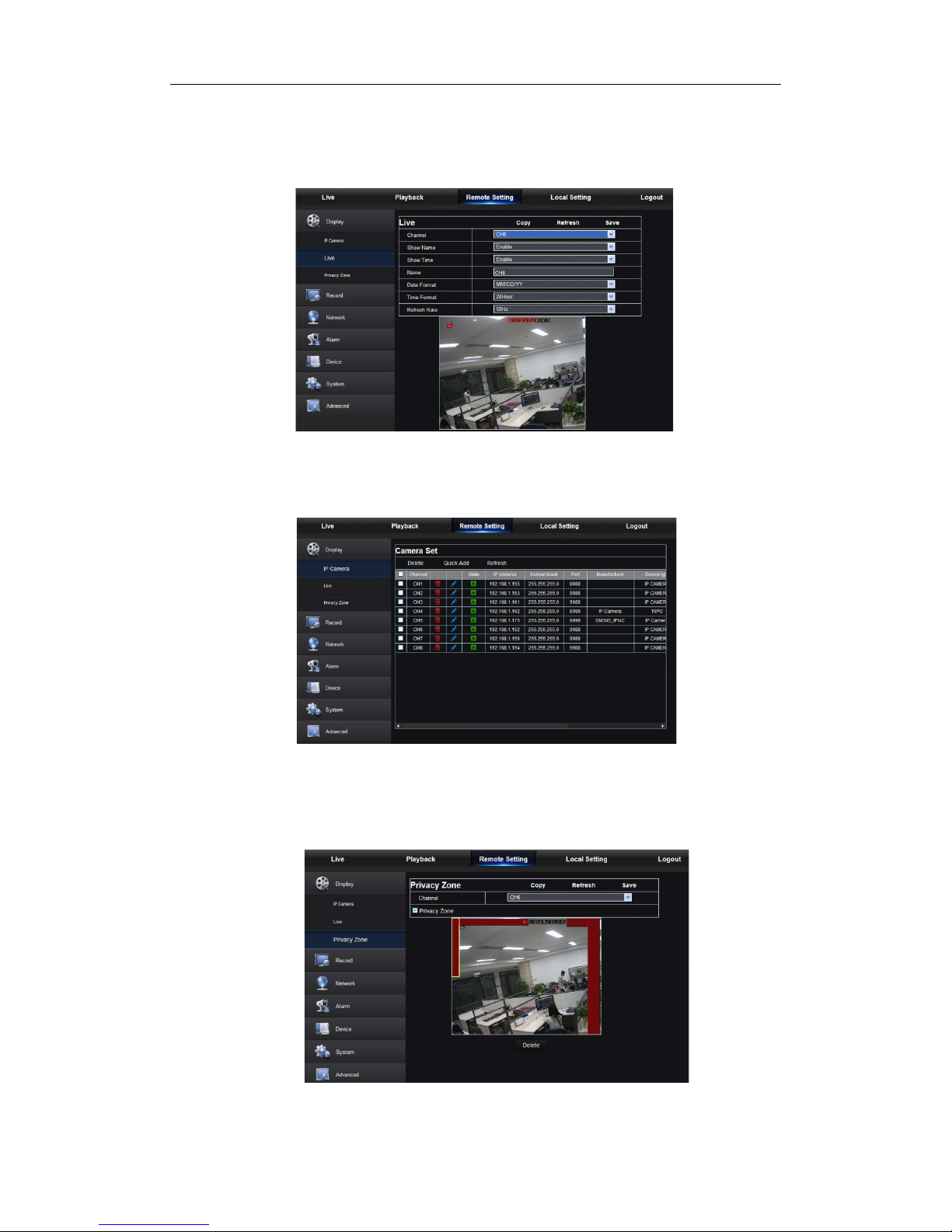
Unfold [Display] option to f ind its sub-options: IP Camera, Live and Privacy zone.
1. Live: Y ou may chang e channel name, position, c hannel preview and relevant par ameters.
If show time is set as <d isable>, curr ent NVR sy stem time wi ll not appear on t he screen
on Live mode.
Picture 5-12
3.IP Camera:Display the information of added IPC. It can quic kly add the on-lin e IPC and
delete the added IPC, as shown in Picture 5-13.
Picture 5-13
4. Privacy Zone: Each channel can set 4 priv acy zones, as shown in Picture 5-14.
The relevant parameters should be consistent with N VR local setting. Select
zones to be deleted and click “Delete” and click “Save” at up-right corner.
Picture 5-14
Page 40
USER MANUAL
35
5.3.3.2 Record
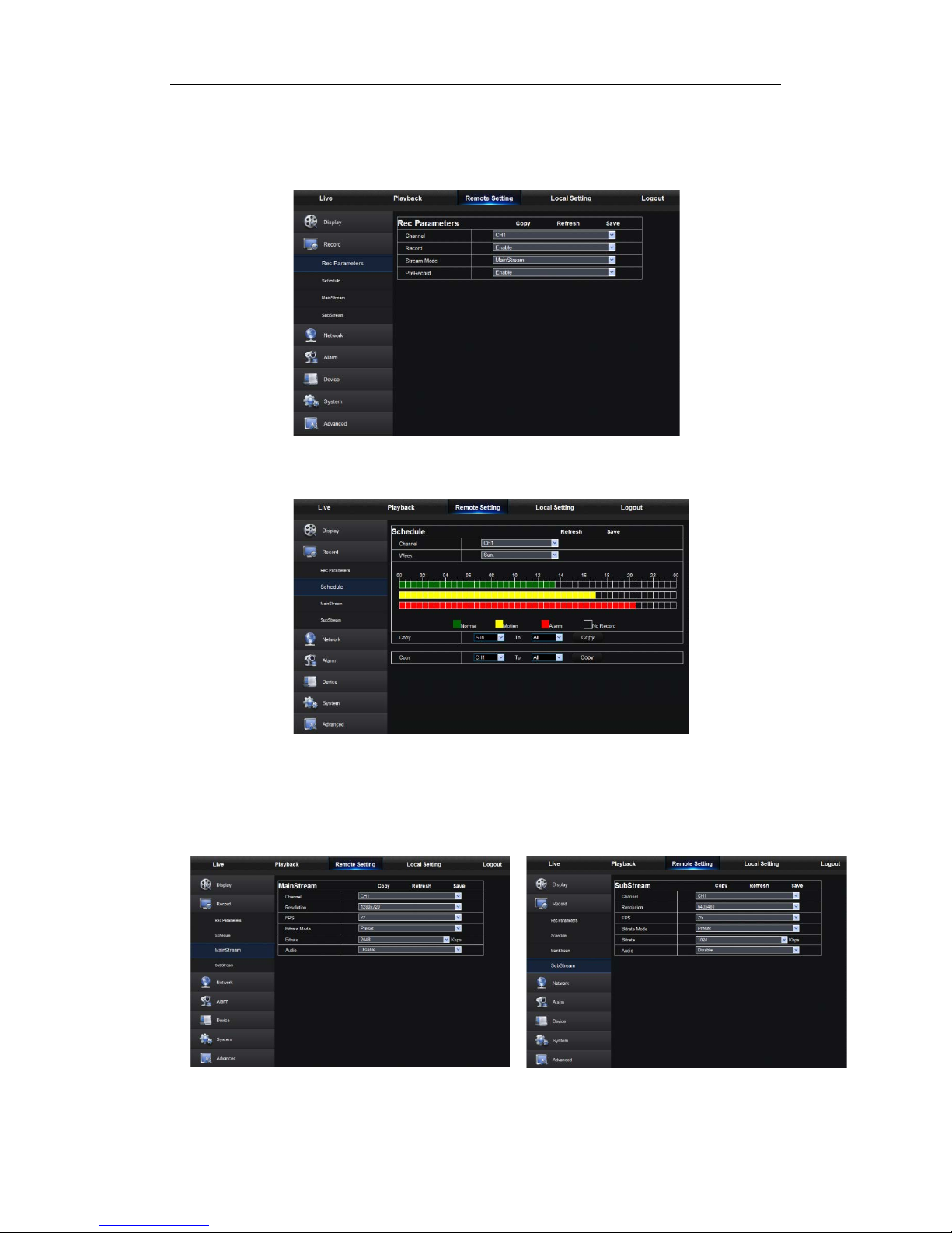
Click <Record> option to unfold its sub-options: Record parameter, Schedule and Stream
configuration.
1. Record Parameters. The parameters should be consistent with NVR local setting, as
shown in Picture 5-15.
Picture 5-15
2. Record Schedule. The parameters should be consistent with NVR local setting, as
shown in Picture 5-16.
Picture 5-16
Green stands for Normal record; Yellow stands for Motion detection; Red stands for I/O
trigger record.
3. Stream setting. User may set Mainstream and Substream, as shown in Picture 5-171 and 5-17-2. The relevant par am et er s should be consistent with NVR local setting.
Picture 5-17-1 Pictur e 5-17-2
Page 41
USER MANUAL
36
5.3.3.3 Network
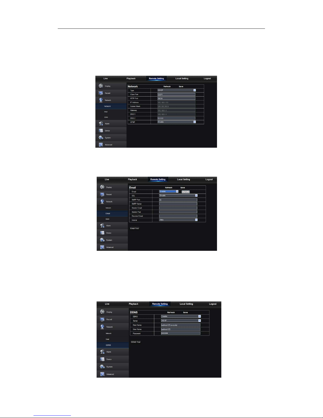
Unfold <Network> to show its sub-options: Network, Email, and DDNS configuration, as
shown in Picture 5-18.
1. LAN setting: NVR supports Static/DHCP/PPPOE modes. System default network type
is <Static>. User can set parameters as required. After the network parameters are
modified successfully, NVR will automatically restart.
2. Email: Set NVR alarm Email configuration parameters, including Email address, SSL,
Email Enable, Interval and Email Sched ule, etc. Detailed paramet ers should b e consistent
with NVR local setting. Refer to Pi ct ur e5-19.
3.DDNS: After user appli es for DD NS serv ice, y ou coul d enabl e <D DNS> funct ion unde r
any one network type mode (Static, DHCP and PPPoE). And you may remotely visit the
NVR through domain name (http://domain name: Web port No.). When visiting NVR by
using DDNS, user should make sure port and current IP can be normally connected in
public network. Details sett ings, including server address, host, user , and password, should
be consistent with NVR local setting. Please refer to Picture 5-20.
Picture5-19
Picture 5-18
Picture5-20
Page 42
USER MANUAL
37
5.3.3.4 Alarm
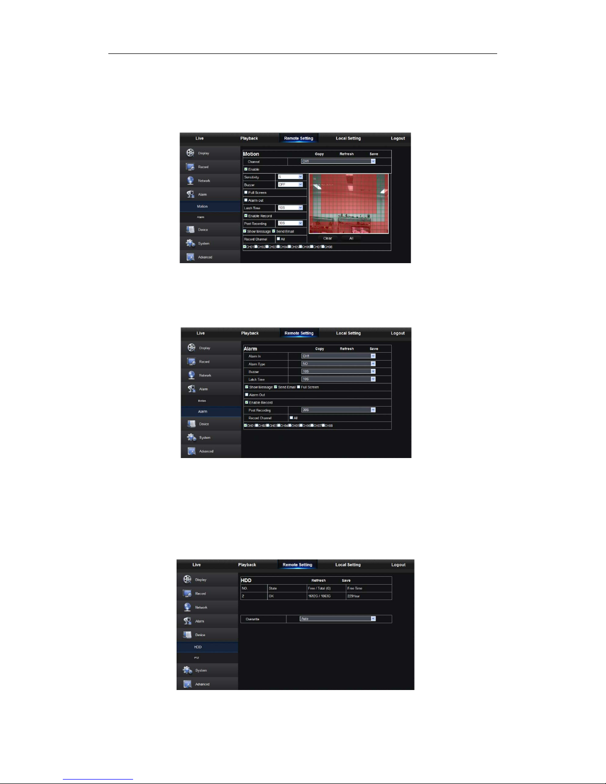
Alarm setting includes Motion Detection and I/O Alarm Para meters.
1. Motion Detection: Configure Sensitivity, Alarm out, Alarm Record and Alarm Capture,
etc. Detailed setting shoul d be consistent with NVR local set ting (Shown as Picture 5-21).
Picture 5-21
2. I/O alarm setting (If available): Set parameters for I/O Alarm, Alar m Out, Alar m Record,
Send Email, etc. Detailed setting should be consistent with NVR local setting (Shown as
Picture 5-22).
Picture 5-22
5.3.3.5 Device
Click <Device> to unfold its sub-options: HDD
HDD
User may check HDD status of NVR and overwritten time. Detail setting should be
consistent with NVR local setting. Please refer to Pict ure 5-23.
Picture 5-23
Page 43
USER MANUAL
38
5.3.3.6 System
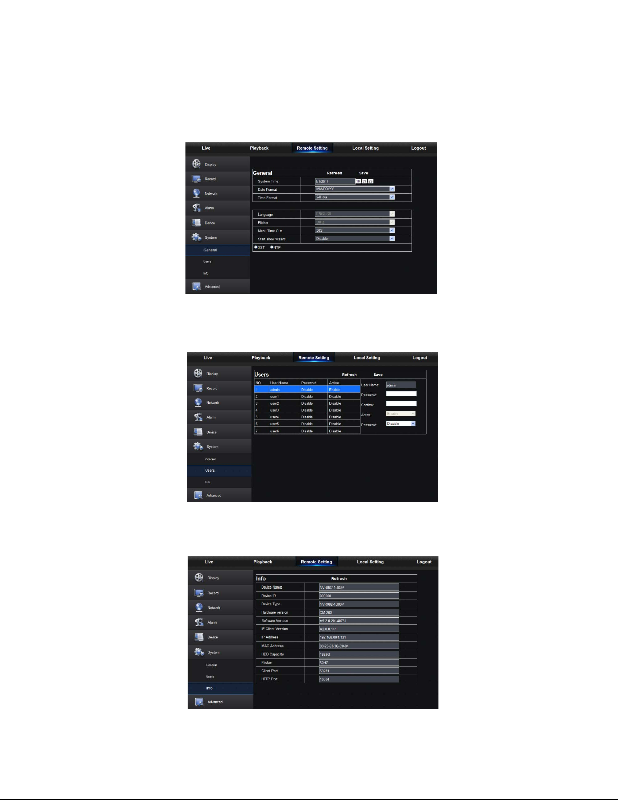
Click <System> option to unf old its sub-options: General, Users and information.
1. General
User may check NVR language and video system and set system time, date/time format,
menu display time, DST and NTP parameters shown as Picture 5-24. Detailed setting
should be consistent with NV R local setting.
Picture 5-24
2. Users
User may configure user name and password shown as Picture 5-25. Detailed setting
should be consistent with NV R local setting.
3. Information
User may search device name, device number, device type, MAC addr ess , software
version, IE version and hardw ar e version of NVR shown as Picture 5-26.
Picture 5-25
Picture 5-26
Page 44
USER MANUAL
39
5.3.3.7 Adv anced
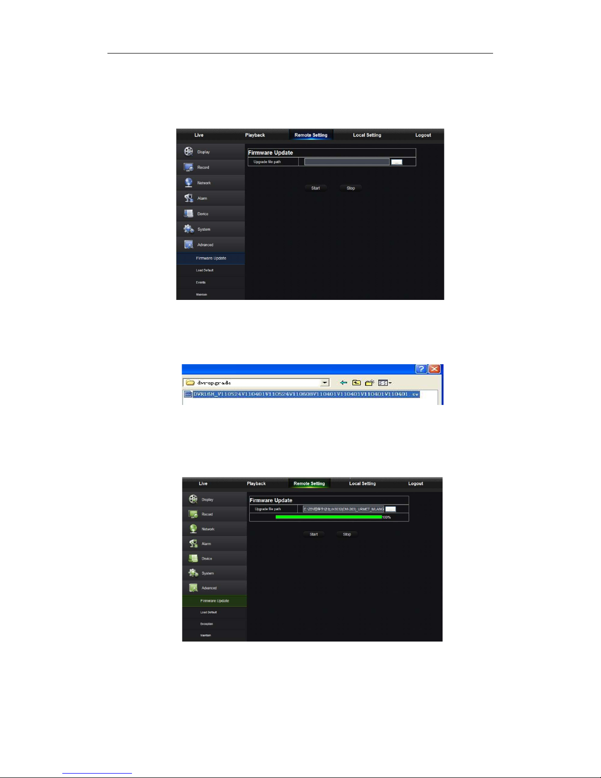
Click Advance to unfold its sub-options: Firmware Update, Load default, Events and
Maintain.
1. Firmware Update
User may remotely update NVR system, as shown in Picture 5-27.
Picture 5-27
Updating procedure:
Firstly, select the update fi le path. The file format is . sw. Pleas e refer to Picture 5-28.
Picture 5-28
Secondly, click “Start” to start updating. The updati ng progres s can be seen on t he screen,
as shown in Picture 5-29.
Picture 5-29
Page 45
USER MANUAL
40
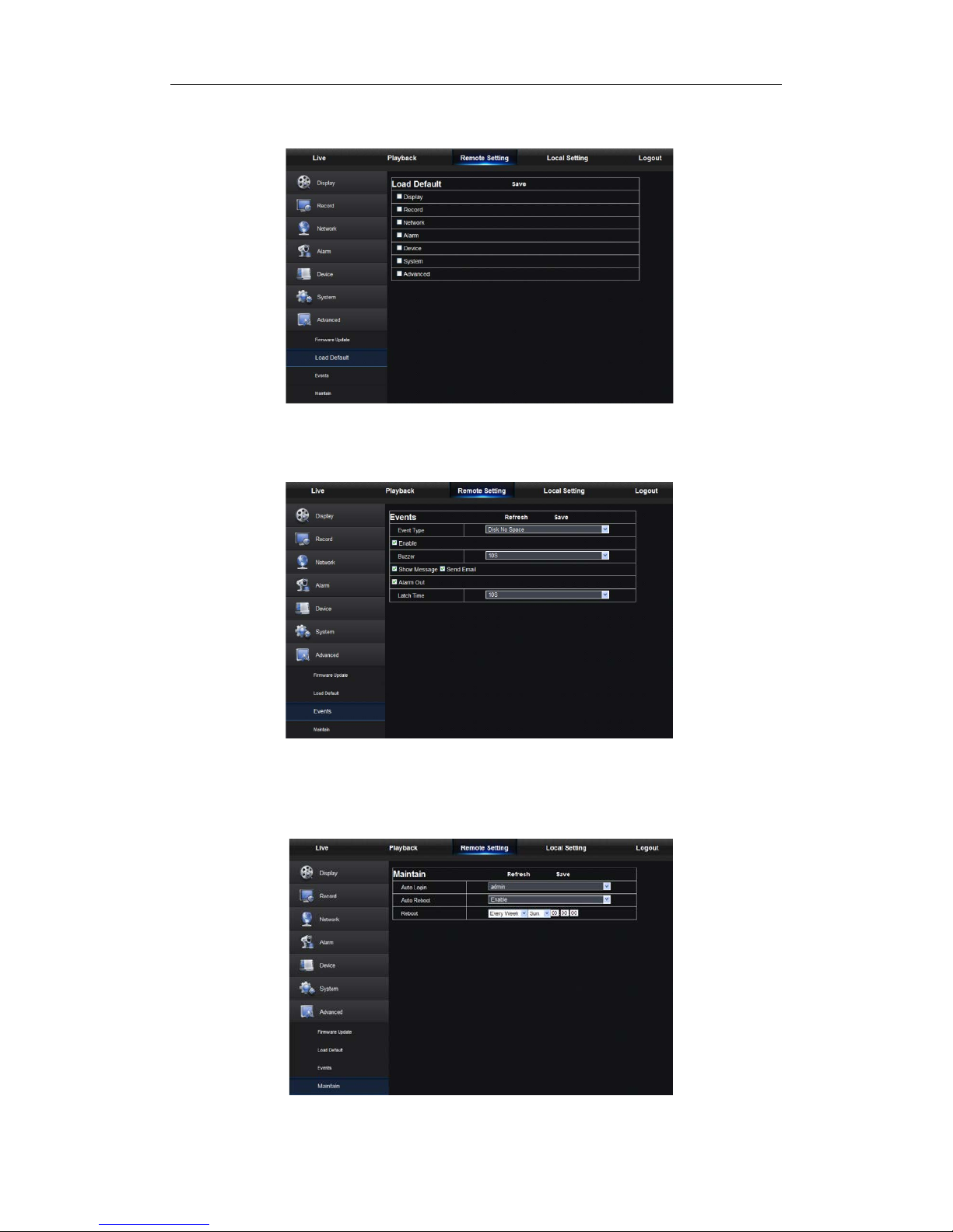
2. Load Default
User may remotely restore default parameters of NVR, with same setting method as that
of NVR, shown as Picture 5-30.
Picture 5-30
3. Events
User may configure Event Type, Buzzer, Send Email, Show Message and other
parameters shown as Picture 5-31. Detailed setting should be consistent with NVR local
setting.
4. Maintain
Allow you remotely set aut o maint ain time for NVR show n as Pictur e 5-32. Det ailed s etting
should be consistent with NV R local setting.
Picture 5-31
Picture 5-32
Page 46
USER MANUAL
41
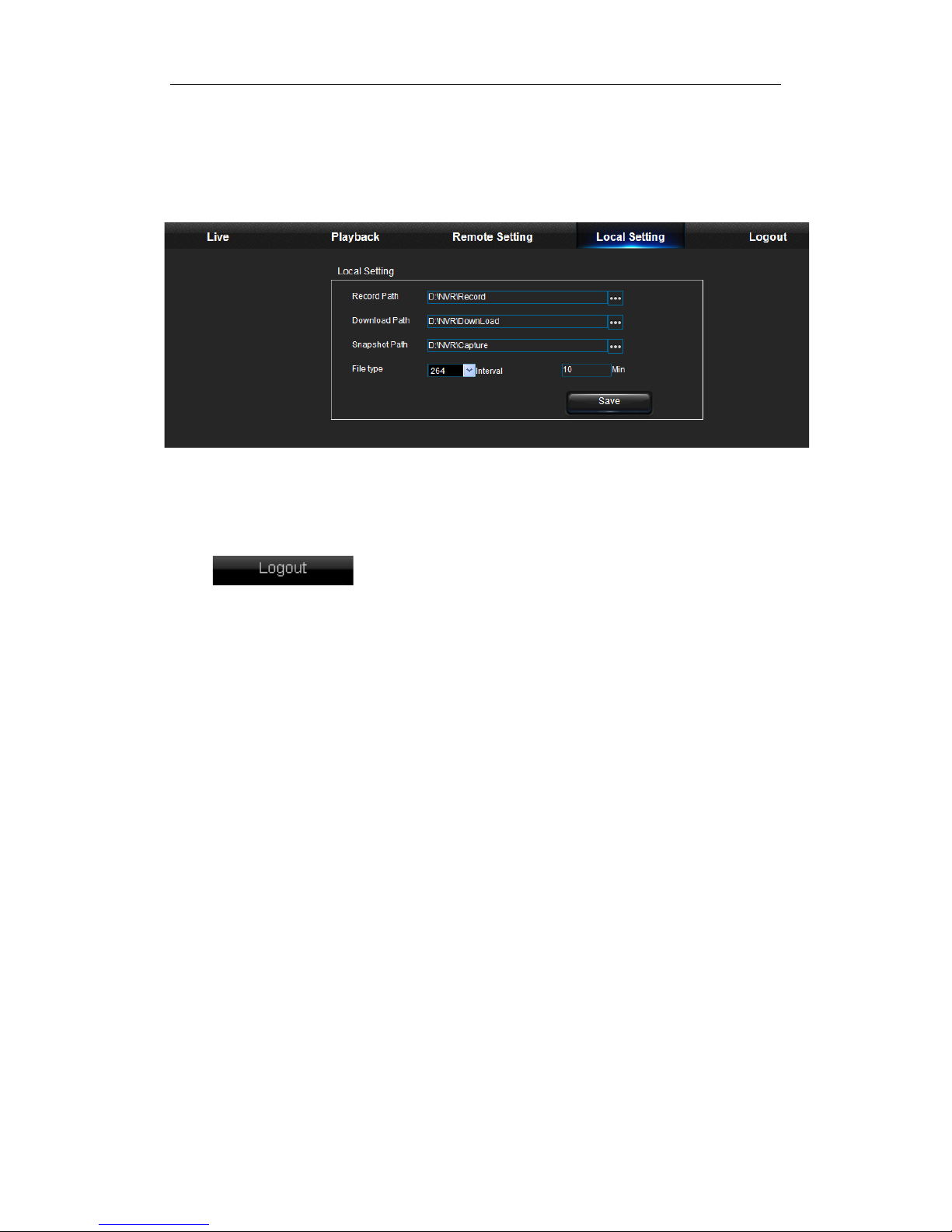
5.3.4 Local Setting
User may set Record Path (save Live record and Playback clip file), Download Path for
remote file, Snapshot Path for captured pictures, Interval for switching record files
(Packaging time), and File type (H264 and AVI) shown as Pictur e 5-33.
Picture 5-33
5.3.5 Logout
Click to log out and return to the Login interface.
Page 47

USER MANUAL
42
Chapter 6 Appendix
6.1 Troubleshooting
1. Q: What can I do if the system does not detect t he HDD?
A: Check if the power supply system is properly connected along with the data cord
and power cable. Check if someth ing wrong with the HDD interface. Or you may check
if your HDD is supported by referr ing to the specifications or descriptions.
2. Q: I have changed the password but forget the new password, how can I access the
system?
A: If you forget system password, please contact our technical support team for
assistance. These device s ar e speci fi cal ly designed not to easily reset the password,
so we strongly suggest user to set password easy to be remembered and relatively
safe. If you have safety r equirement, please do n ot set very simply passwor d, such as
000000.
3. Q: There is abnormal video signal or ev en no video signal by conn ecting the NVR and
camera together and pow er supply for both devices is okay. What is wrong?
A: Check networ k cable at NVR side to see if the ca ble is firmly conn ected. If it is worn
out it may need to be replaced.
4. Q: How to prevent NVR from being influenced by heat?
A: The NVR needs to dissipate heat while it is running. Please place the NVR in a
place with good air circulation and away from he at sources to ensure stability and life
of the NVR.
5. Q: W hy doesn’t the remote controller doesn’t work whilst the monitor screen is okay
and panel keys are functional?
A: Operate again by aimin g the r emote c ont roller at t he IR rec eiv er on front p anel. If it
still doesn’t work, please chec k if the batteries in t he remote contro ller are dying. If not,
check if the remote controller is broken.
6. Q: I want to take out HDD from my PC and install it in NVR. Can will it work?
A: All HDDs supported by the system can be used. But remember, once NVR
reformats the HDD, all pre vious data on your HDD will be lost.
7. Q: Can I playback while recording?
A: Yes. The system supports the funct i on of playing while recording.
8. Q: Can I clear some records on HDD of NVR?
A: In consideration of the file security, you may not clear part of records. If you want
to remove all the records, you can format HDD. Otherwise, using overwrite mode will
begin to record over the oldest fo ot age once the storage is full.
9. Q: Why can’t I log in NVR client?
A: Please check if the network connection settings are correct and RJ-45 / Ethernet
port connection is secure. Check if your account and passw or d are input correctly.
Page 48

USER MANUAL
43
10. Q: Why can’t I find any records during playback?
A: Please check if th e data line conn ection for HDD is O K and syste m time is properly
adjusted. T ry a few times and restar t. If it still doesn ’t work, check if the HDD is broken .
Check if recording was turned on.
1 1. Q: Why doesn’t dynamic detection work?
A: Please check if the motion detection a larm setting at IPC side is correct and if the
sensitivity is set too low.
12. Q: Why doesn’t alarm work?
A: Please check if the alarm setting, alarm connection and alarm input signals are
correct.
13. Q: Why does the buzzer keep sounding?
A: Please check the alarm setting, check if motion detection function is enabled and
object motion is detected all the time and if I/O alarm is set as Always Off. Besides,
refer to corresponding HDD alarm setting.
14. Q: Why can’t I stop recording by pressing “STOP” button or click “Stop Recording” in
context menu?
A: Pressing Stop button can only st op m anual record. If you want to st op Scheduled
recording in a certain time, please change the setting to No Record. To stop Startup
recording, please change record mode to scheduled recording or manual recording.
Then you may stop recording by the prescribed methods. Another way of stopping
recording is to set channel in recor d setting as Off.
6.2 Usage Maintenance
1. To shut down NVR, please firstly shut down t he system and then turn off the power.
Do not turn off the power directly or HDD data will be lost or damage d.
2. Keep NVR away from heat sources or hot environments.
3. Clean the internal dust and around the dev ice regularly. Make sure the good
ventilation of NVR so as to ensure the good heat dissipation.
4. Do not hot wire cables in at ports, or the ports may be damaged and warr ant y will be
void.
5. Check the HDD cable and data cable regularly to see if they are aging.
6. Prevent the audio and video signals of NVR from interference from other nearby
electronic devices. Prevent the HDD from being damaged by static electricity and
induced voltage.
7. If the network cable is frequently unplugged, it is suggested to replace connecting
line regularly, or the input signal may be unstable.
8. This is A class product. it may develop wireless inte rferen ce in dur i ng t he pr oduct
lifecycle. Under this situation, the user will need to take precautions.
Page 49

USER MANUAL
44
Chapter 7 Warranty
Thank you for purchasing MaxxOne pr oducts. In order to prot ect your rights and inter ests,
please read the following Warranty Policy c arefully.
7.1 Limited Warranty
This document sets out the standard MaxxOne warranty policy for MaxxOne products.
MaxxOne provides limited warranty to all MaxxOne products purchased within the
European Economic Area. The warranty covers the main device, antenna and external
power supply for any mater ial or workmans hip defects durin g the W arranty Period (define d
below). Packaging, various cables, software products, technical data and other
accessories are not covered under this warranty. The maximum liability of MaxxOne is
equal to or no higher than the product's purchased price.
MaxxOne will not refund the defective products. If covered by the terms of this warranty
MaxxOne will repair or replace the defective product at MaxxOne’s discretion. If the
returned product is discontinued, and a repair is not economically possible, MaxxOne will
replace it with an equivalent pr oduct .
The purchaser is respons i ble for any carriage costs for sending products to and from their
authorised service centre, details are laid out in the Normal R eplacement Procedure.
Note: Internal hard drives installed post-production into our digital video recorders are not
installed by MaxxOne and are also not covered under this warranty, please refer to the
hard drive manufacturer’s own w arranty terms or cont act the original pl ace of purchase fo r
assistance.
7.2 Warranty Period
The warranty period for this product is 2 years. The ‘Warranty Period’ duration is from the
date of purchase by the original end-user cust omer, if the Equipment has be en repaired or
replaced under warranty, the warranty applies until the end of the or iginal Wa rranty Period,
or three (3) months from the date of such repair/replacement , whichever is longer.
7.3 Warranty Exclusions
Conditions disqualifying a product from Warr anty include but are not limite d to the following:
• Any defect caused by misuse, improper installation or maintenance that is not
required by MaxxOne;
Page 50

USER MANUAL
45
• Any defect caused by softw ar e, virus or improper use of self-made and non-public
software;
• Any product beyond the limited free replac ement and repair period;
• Any equipment where the manufacturer’s serial nu mber has been altered, dele ted,
removed, or made illegible;
• Any discrepancy between the product type and barcode or warrant y card;
• Any unauthorised modification to the supporting setting files or any authorized
disassembly and repair;
• Any defect caused by improper use in the working cond it ion s beyond those stated
in the literature (for exam ple: wor king conditions that are too hot/ cold, wet/dr y; high
altitude; instable electric c ur r ent and voltage and so on)
• Any defect caused by personal disaster or improper maintenance, such as
mechanical damage, serious oxidation and rusting, animal damage, over exertion
and so on;
• Any defect caused by transportation or loa ding during returning voyage;
• Any defect caused by natural disaster such as earthquake, fire, flood, thunder
strike and so on;
• Any other defects that are not caused by workmanship, technique, product quality
and the like;
• Any consumable parts
• Any equipment which has been adjusted or adapted without MaxxOne’s prior
written consent, including (but not limited to): cutting/altering cables (internal or
external), upgrading the E quip ment bey ond spe cif icat ions or feat ures des cribed in
the instruction manual, or modifications to the Equipment to conform it to national
or local technical or safety standards in countries other than those for which the
Equipment was specifica ll y designed and manufactured. *
Conditions that Disqualify Pr oduct from Warr anty in the external power supp ly include:
• The returned power supply has obvious damage, fissure, broken pins, severe
deformation.
• The returned power cord is broken, has naked core and damages like this.
*Installation of a hard disk drive to a bare bones unit is an accepted modification and is
allowed under this policy under t he condition that no other internal parts are affected.
8.4 Warranty Claims and Validation
Warranty cla ims are subject to:
• The purchaser presenting to MaxxOne (eith er via the properly authoriz ed MaxxOne
distribution partner from whom the product was purchased or by contacting
MaxxOne directly, see Normal Replacement Procedure stated below) the original
sales invoice (indicating the date of purchase by the original end-user customer,
Page 51

USER MANUAL
46
serial number and the original dealer's name) together with the defective
Equipment within the Warranty Period; an d
• Inspection by MaxxOne (or its authorized service agent) disclosing to the
satisfaction of MaxxOne that the defect in the Equipment has arisen from defects
in workmanship or materi als during the Warranty Period;
• none of the exclusions apply.
8.5 Limitation of Liability
The express warranty above shall be the full extent of MaxxOne’s liability. Accordingly,
MaxxOne disclaims all other liability for loss or damage howsoever caused (except for
death or personal injury resulting from proved negligence) arising out of the purchase,
possession, sale or use of the equipment and all other terms, conditions, and warranties
express or implied, arising out of trade usage or otherwise are hereby excluded. In no
event shall MaxxOne be liable for any special, incidental or consequential damages
including, but not limited to the infringement of any intellectual property rights, delays, or
inaccurate information or advice. Notwithstanding the foregoing the customer's statutory
rights (if any) are not af fected.
8.6 Miscellaneous Provisions
• No person, including any distribut or, dealer, agent o r representat ive of M axxOne is
authorised to assume for M axx O ne any liability on its behal f or in its name.
• The purchaser is not entitled to rely on any representations made either orally or
in writing by or on behalf of MaxxOne save for those made fraudulently.
8.7 Standard Warranty Conditions
Customer Data on media:
MaxxOne has no liability to the owner of the Data or any third party for any loss, damage
or corruption to any data, information or footage (together "Data") stored on any media
passed to MaxxOne. In the event that the media contains Data, the destruction of which
would lead to the owner suffering loss, Ma x xO ne therefore recom men ds t hat the owner of
such Data, makes suitable copies o f all such Data before the media is supplied to Max xOne,
and/or obtains adequate insur ance to protect themselves fro m s uch loss.
8.8 Repair/Replacement Procedure
Please refer to http://www.maxxone.com/warranty for the latest information on our repair
and replacement procedur e.
Page 52
www.maxxone.com
The material in this document is the intellectual property of MaxxOne
• No part of this manual may be reproduced, copied, translated, transmitted, or published in any
form or by any means without our prior permission.
• Our products are under continual improvement and we reserve the right to make changes without notice. No guarantee is given as to accuracy of its contents.
• We do not undertake any responsibility for the harm caused by using our product.
• The product picture may differ from actual product, and is only for your reference. The accessories
contained may differ by region. For details of accessories, please refer to your local distributor.
COPYRIGHT RESERVED
Visit our website; www.maxxone.com for full warranty details.
Please note that our warranty covers the NVR recorder shell
only and does not include internal hard drives. Any installed
hard drive warranty will be the responsibility of your supplier
or local distributor.
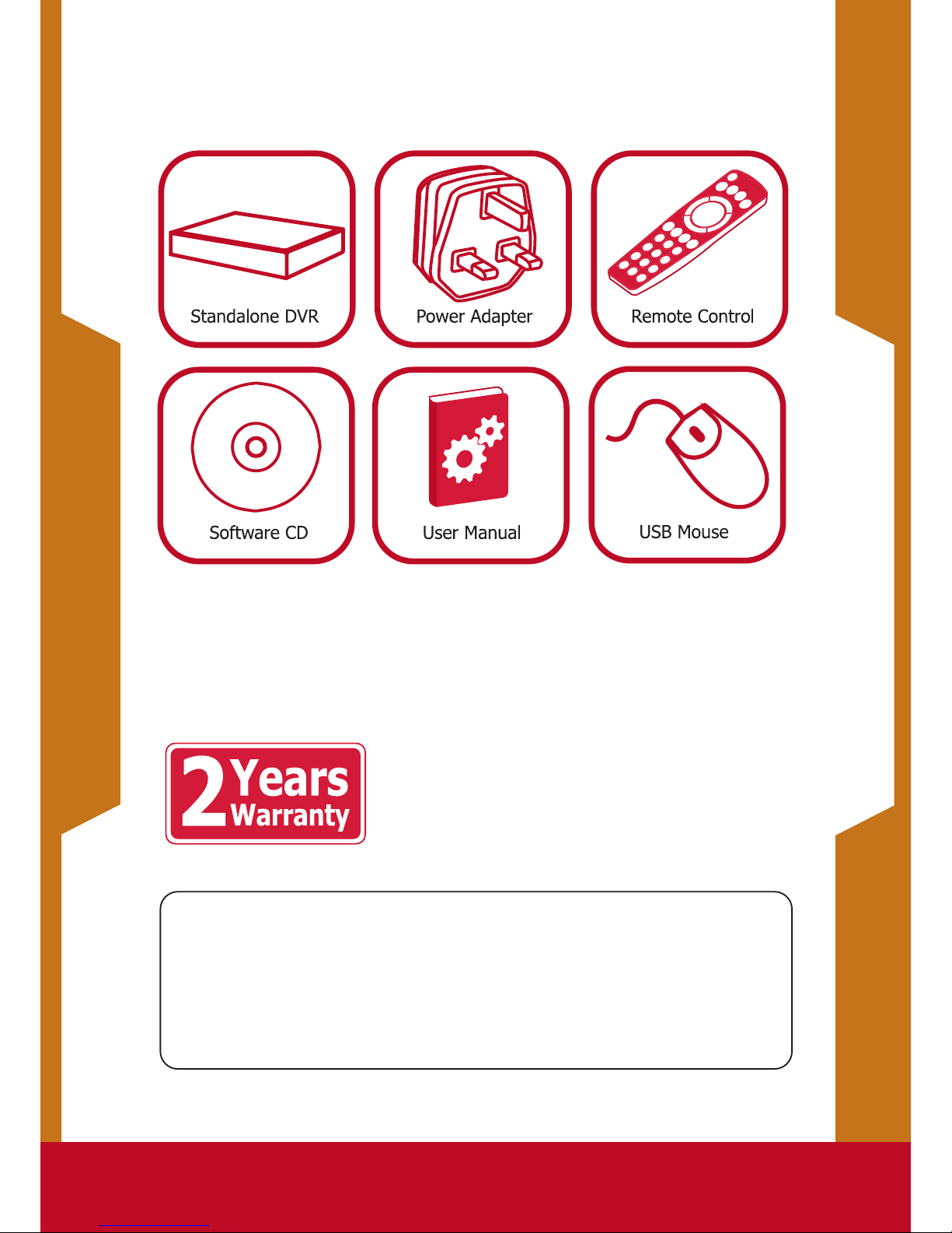
Box Contents
 Loading...