

Page 1
MAXX ICE Marine Crescent
Ice Maker Instruction Manual
Page 2

Congratulations on your new MAXX ICE Marine Crescent Ice Maker. To ensure proper operation,
please read this Instruction Manual carefully before using this product. Keep this manual in a safe
place for future reference.
Page 3

© 2019 The Legacy Companies
Crescent Ice Maker Instruction Manual
TABLE OF CONTENTS
DISPOSAL ...............................................................................................................................5
SAFETY ...................................................................................................................................6
SAFETY PRECAUTIONS .........................................................................................................6
FEATURES AND SPECIFICATIONS ....................................................................................... 8
INSTALLATION INSTRUCTIONS .......................................................................................... 11
BUILT-IN INSTALLATION ....................................................................................................... 12
ELECTRICAL CONNECTION ................................................................................................14
EXTENSION CORD ...............................................................................................................14
WATER SUPPLY .................................................................................................................... 15
LEVELING THE ICE MAKER ................................................................................................. 15
DOOR REVERSAL ................................................................................................................. 15
OPERATING INSTRUCTIONS ..............................................................................................18
ICE MAKING INSTRUCTIONS ..............................................................................................18
NORMAL SOUNDS ................................................................................................................ 19
POWER FAILURE .................................................................................................................. 19
FLANGE KIT INSTALLATION ............................................................................................... 20
INSTALLATION ......................................................................................................................21
CARE AND MAINTENANCE ................................................................................................. 22
CLEANING AND MAINTENANCE .......................................................................................... 22
Exterior Cleaning...............................................................................................................22
Interior Cleaning ................................................................................................................23
Winterizing ........................................................................................................................23
3
Page 4

TABLE OF CONTENTS
© 2019 The Legacy Companies
Crescent Ice Maker Instruction Manual
Recommissioning ..............................................................................................................23
Start-up .............................................................................................................................23
Condenser Cleaning .........................................................................................................24
TROUBLESHOOTING ........................................................................................................... 25
PARTS INFORMATION .........................................................................................................27
EXPLODED VIEW ..................................................................................................................27
PARTS LIST ...........................................................................................................................28
WARRANTY ........................................................................................................................... 29
4
Page 5

© 2019 The Legacy Companies
Crescent Ice Maker Instruction Manual
DISPOSAL
INFORMATION
1
Thank you for choosing the MAXX ICE Marine 14" Crescent Ice Maker. Always follow the instructions
provided in this manual to obtain the very best performance from your ice maker. We trust that your
MAXX ICE Marine Crescent Ice Maker will provide the performance and reliability that we stand for.
Always keep this manual in a safe place for future reference.
This symbol on the product or its packaging indicates that this appliance cannot be treated as
normal domestic trash; it must be handed in at a collection point for recycling electric and electronic
appliances. Your contribution to the correct disposal of this product protects the environment.
Further information about the recycling of this product can be obtained from your local municipal
authority.
5
Page 6
© 2019 The Legacy Companies
Crescent Ice Maker Instruction Manual
SAFETY
2
!
!
Do not attempt to install or operate the unit until you have read and understood the safety precautions
in this manual. Safety Precautions throughout this manual are labeled.
This safety alert symbol appears with most safety statements. It means attention,
become alert, your safety is involved! Please read and abide by the statement that
follows the safety alert symbol.
WARNING
Indicates a hazardous situation that, if not avoided, could result in death or serious injury.
NOTICE
Indicates a situation which can cause damage to the components and/or the environment, or
cause the equipment to operate improperly.
SAFETY PRECAUTIONS
• Do not connect or disconnect the electric plug when your hands are wet.
• Never unplug the ice maker by pulling on the power cord. Always grip the plug rmly and pull
straight out from the outlet.
• Never clean ice maker parts with ammable uids. Do not store or use gasoline or other
ammable vapors and liquids in the vicinity of this or any other appliances. The fumes can create
a re hazard or explosion.
• Before proceeding with cleaning and maintenance operations, make sure the power line of the
unit is disconnected and the water line is shut off.
• Never allow children to operate, play with or crawl inside the ice maker.
• Do not touch the evaporator with your hand when the machine is operating.
• Unplug the ice maker or disconnect power before cleaning or servicing. Failure to do so can result
in electrical shock or death.
• Do not attempt to repair or replace any part of your ice maker unless it is specically
recommended in this manual. All other servicing should be referred to a qualied technician.
6
Page 7
SAFETY
© 2019 The Legacy Companies
Crescent Ice Maker Instruction Manual
• This appliance can be used by children from ages 8 years and above and by persons with
reduced physical, sensory or mental capabilities or lack of experience and knowledge if they have
been given supervision or instruction concerning use of the appliance in a safe way and they
understand the hazards involved. Children shall not play with the appliance.
• Use two or more people to move and install the ice maker. Failure to do so can result in back or
other injury.
• To ensure proper ventilation for your ice maker, the front of the unit must be completely
unobstructed.
• This ice maker is designed for non-commercial use only.
• Although the unit has been tested and cleaned at the factory, due to long-term transit and storage,
the rst batch of cubes must be discarded.
• Remove the packing materials and clean the ice maker before using.
• Turn on the water supply tap before switching on the ice maker. Never turn the water supply tap
off when the ice maker is working.
• Keep the door closed in order to reduce ice melting and to promote proper ice formation. Open
the door only when taking ice from the unit.
• If the ice maker will not be used for a long time, thoroughly clean it before the next use. Carefully
follow any instructions provided for cleaning or the use of sanitizing solution. Do not leave any
solution inside the ice maker after cleaning.
• Do not touch the condenser surfaces. They are sharp and can be easily damaged.
• Do not use solvent-based cleaning agents or abrasives on the interior. These cleaners may
transmit taste to the ice cubes, or damage or discolor the interior.
• Do not use the apparatus other than for its intended purpose.
• Cleaning and user maintenance shall not be done by children without supervision.
THE MANUFACTURER DISCLAIMS ANY RESPONSIBILITY IF THE ABOVE INSTRUCTIONS ARE
NOT FOLLOWED.
7
Page 8
© 2019 The Legacy Companies
Crescent Ice Maker Instruction Manual
FEATURES AND
SPECIFICATIONS
3
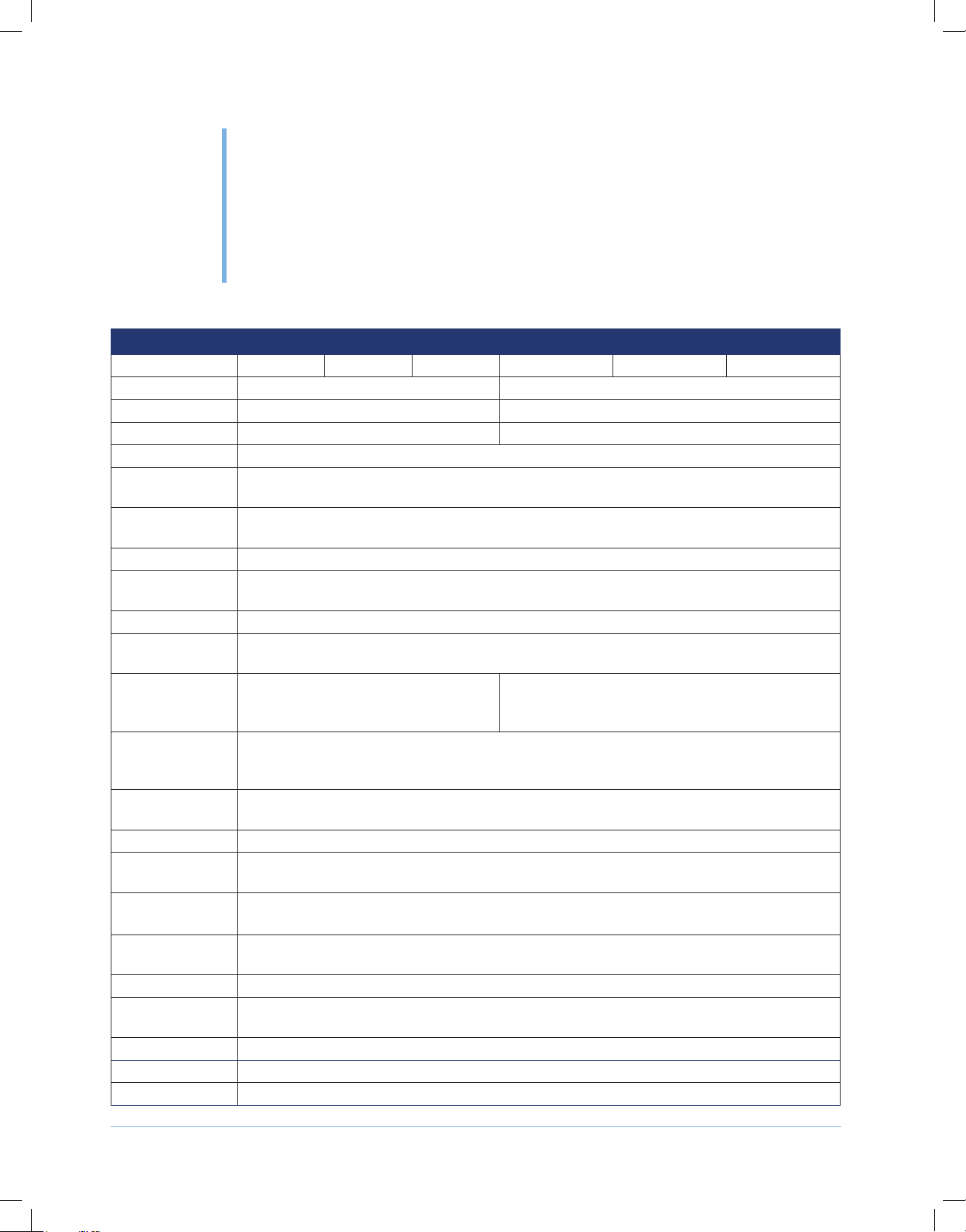
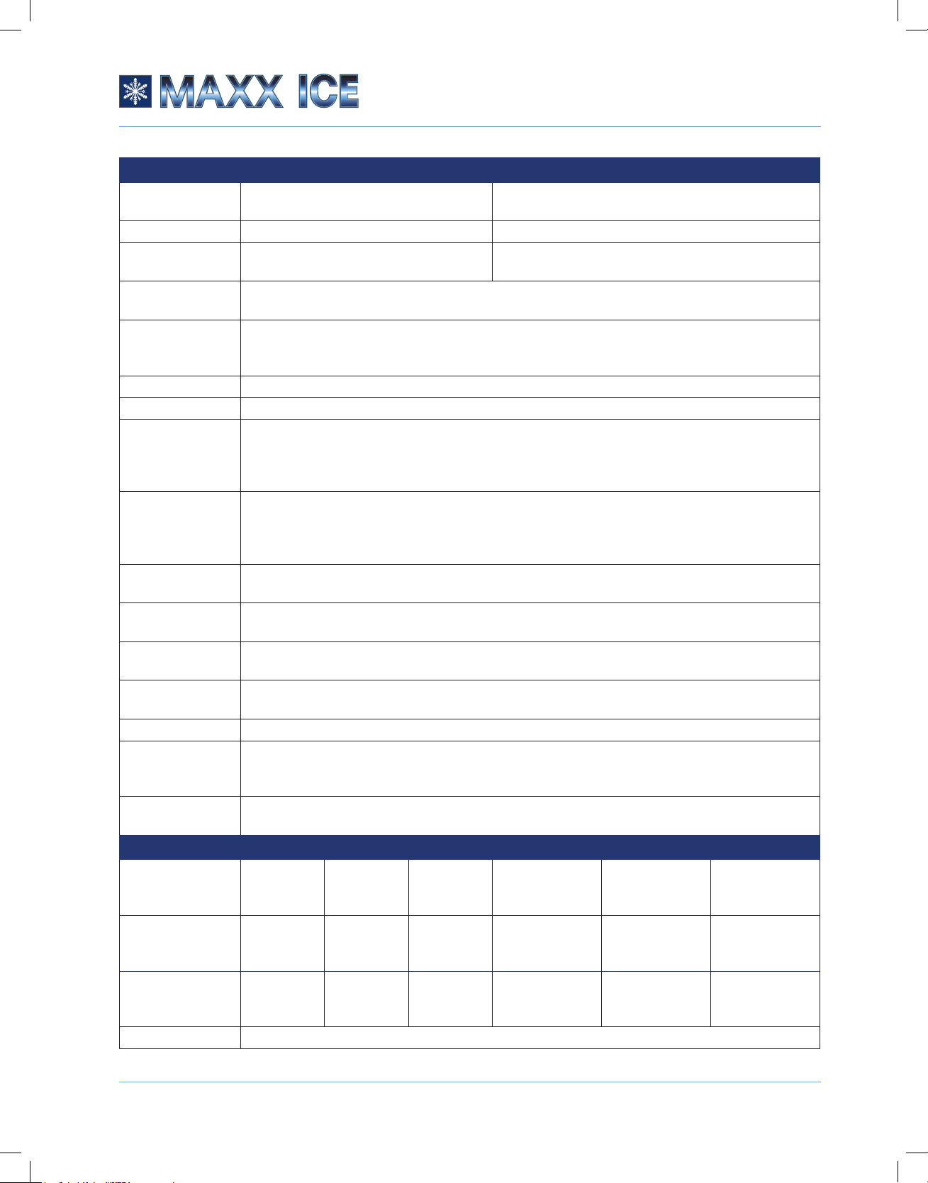
GENERAL FEATURES
Model MMAR25S MMAR25W MMAR25B MMAR25S[E0] MMAR25W[E0] MMAR25B[E0]
Power 115V/60Hz 220V/50Hz
UL/cUL Approval UL NA
CE Certicate NA CE
Cabinet Insulation NON CFC polyurethane foam with agent Cyclopentane
Ice Production
Capacity
Ice Storage
Capacity
Ice Shape Crescent Shaped Cube
Ice Size (Inches
(mm))
Ice Weight (g) 10
Ice Quantity per
Cycle
Ice Making/
Harvesting Rated
Current (amp)
Power
Consumption
(kWh/lb of ice)
Water
Consumption
Defrost Type Manual
Controls Mechanical Thermostat monitors ice-making operation to ensure the maximum daily ice
Power On/off
Switch
Auto Shut-off
When Ice Bin is Full
Cycles On/Off
High/Low Side
Pressure (PSIG)
Refrigerant R134A, 2.65 oz. (75g)
Compressor 1/6 HP
Exposed Screws All color matched to cabinet or liner, depending on location
up to 25 lbs./24 hrs.
up to 12 lbs. removable and dishwasher safe ice bucket
1/2” x 3/4” x 2-1/2” (12 x 20 x 60)
12
1.8/1.5 1.0/0.75
<25 kWh/100 lb
Use less than 3 gallons of water for approximately 25 lbs. of ice
production. Compressor is OFF during ice harvest. Fast ice-making and energy saving.
In the front of unit
Yes
380/130 (2.6 MPa/0.9 MPa)
8
Page 9
FEATURES AND SPECIFICATIONS
© 2019 The Legacy Companies
Crescent Ice Maker Instruction Manual
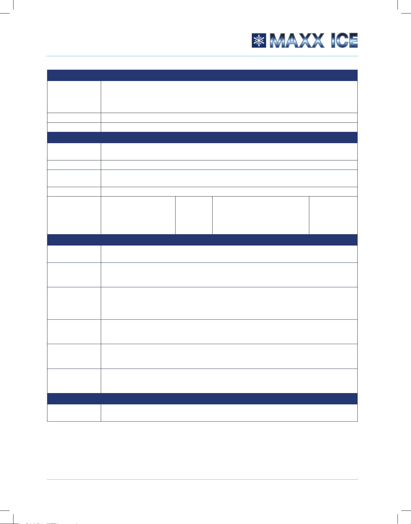
INSTALLATION
Power Port and
Plug
Volt Range 104~127V 187~242V
Maximum Amp
Fuse
Ambient Operating
Range (F)
Water Pressure
Operating Range
(PSI)
Marine design Yes
Built-in Capable Flush mounted, Built-in, Free-standing or Counter Top
Cut-Out
Dimensions for
Flush to Cabinet
(W x H x D)
Cut-Out
Dimensions for
Flush to Door
(W x H x D)
Net Weight (lbs
(Kg))
Air Ventilation All ventilation from front, limited vent in the back of unit. No additional clearance required
Removable Ice
Bucket
Adjustable
Leveling Feet
Drain No Drain required. Easy and inexpensive for installation.
Water Supply Inlet
Thread (for Pipe
Fitting)
Water Supply Inlet
Location
CABINET EXTERIOR
Exterior Cabinet
Color
Grille Color Brushed
Door Color Brushed
Door Style Swing door, Right Hand. Field Reversible
6' xed power port with USA Plug Type
NEMA5-15
15 amps 10 amps
50°F~100°F (10ºC~38ºC) Class T
20~120 (0.14 MPa~0.83 MPa)
14-1/4" x 24-5/8" x 16-1/2" (362 x 626 x 420)
15-1/8'' x 24-5/8" x 18-3/8'' (384 x 626 x 466)
around the sides.
Rubber feet reducing vibration noise
Lower Right from Rear (looking from rear, power cord on lower left of rear)
Brushed
Stainless
Steel
Stainless
Steel
Stainless
Steel
Matte White Matte Black
Matte White Matte Black
Matte White Matte Black
6' portable power port with EU/AU/CN/GB/IN 4
types of plug for multiple application
51 lbs. (23 kg)
Yes
UNS 7/16
Brushed
Stainless Steel
Brushed
Stainless Steel
Brushed
Stainless Steel
Matte White Matte Black
Matte White Matte Black
Matte White Matte Black
9
Page 10
FEATURES AND SPECIFICATIONS
© 2019 The Legacy Companies
Crescent Ice Maker Instruction Manual
CABINET EXTERIOR
Door Closing
Assistant
Handle Brushed Stainless Steel
Hinge Brushed Stainless Steel
CABINET INTERIOR
Interior Parts
Color
Interior Light N/A
Cabinet Liner
Color
Door Liner Color White Plastics
Door Gasket
DIMENSIONS – EXTERIOR
Max. Width
(Inches (mm))
Max. Depth
(Inches) Including
Handle
Depth Including
Door, Excluding
Handle (inches
(mm))
Depth of the
Cabinet Only
(Inches (mm))
Height Including
Rubber Feet
(Inches (mm))
Height Excluding
Feet (Inches
(mm))
ACCESSORIES OR OPTIONS
Flange Trim
(Optional)
Plastic door closing assistant design. Positive catch door latch engages automatically when
door is shut and releases when the handle is pulled. It makes the unit hygienic and safe
during sea travel and storage. Leave the door open to allow the air to dry the inside of the
unit when it is powered off.
White
White Prepainted Aluminum. The evaporator tube is covered by the liner avoiding damage.
Magnetic
Magnetic and
Replaceable with color
gray
Flange Kit for ush to door or ush to cabinet. Color match to the cabinet
and
Replaceable
with color
black
24-1/2''~25'' (622~635)
Magnetic and Replaceable with
14'' (356)
17-7/16" (443)
16-3/8'' (415)
14-1/2'' (368)
24'' (611)
color gray
Magnetic and
Replaceable
with color black
10
Page 11

© 2019 The Legacy Companies
Crescent Ice Maker Instruction Manual
INSTALLATION
INSTRUCTIONS
4
IMPORTANT:
• This ice maker should be installed by a licensed plumber only.
• The ice maker must be installed with all electrical and water connections in accordance with state
and local codes.
• A standard electrical supply properly grounded in accordance with National Electrical Code and
local codes and ordinances is required.
• The fuse (or circuit breaker) size should be 15 amperes for 110V and 10 amperes for 220V.
• It is recommended that a separate circuit, servicing only for your ice maker, be provided. Use
receptacles that cannot be turned off by a switch or pull chain.
• This unit MUST be installed in an area protected from the elements (for example, wind, rain, water
spray or drips). Do NOT use the ice maker in outdoor settings.
• The ambient operational temperature should be between 50°F (10°C) and 100°F (38°C). The
input water temperature should be between 41°F (5°C) and 90°F (32°C). Operation outside these
temperatures may result in lowered production or other adverse effects.
• Too much humidity in the air will cause frost to form quickly on the evaporator, requiring more
frequent de-frosting of the ice maker.
• The ice maker should not be located next to ovens, grills or other high-heat resources.
• The unit should be located on a hard, level surface that can support the unit when it is full. It is
important for the ice maker to be level in order to work properly. Otherwise water may not ow
properly through the evaporator (ice mold). The ice production will be less than normal. You may
need to make several adjustments to level it. If needed, you can adjust the height of the ice maker
by turning the feet. See “Leveling the Ice Maker” on page 15.
• To ensure proper service access and ventilation, allow at least 2” (50 mm) clearance at rear, and
1/4” (6 mm) at top and sides. The installation should allow the ice maker to be pulled forward for
servicing if necessary.
• When installing the ice maker under a counter, follow the recommended spacing dimensions
shown. Place electrical and water supplies and drain xtures in the recommended locations.
• The ice maker requires a continuous water supply with a minimum pressure of 15 psi (0.1 MPa)
and a static pressure not to exceed 80 psi (0.5 MPa).
11
Page 12

INSTALLATION INSTRUCTIONS
© 2019 The Legacy Companies
Crescent Ice Maker Instruction Manual
!
• It is always a good idea to lter the water. A water lter can remove taste and odors as well as
particles. Where water is very hard, softened water may result in white, mushy cubes that stick
together. Deionized water is not recommended.
• Make certain that the water supply hose is not pinched, kinked or damaged during installation.
• Check for leaks after the water line is connected.
• Do not kink, pinch or damage the power supply cord between the ice maker and wall or cabinet.
• Before connecting the ice maker to the power source, let it stand upright for approximately 4
hours. This will reduce the possibility of a malfunction in the cooling system from handling during
transportation.
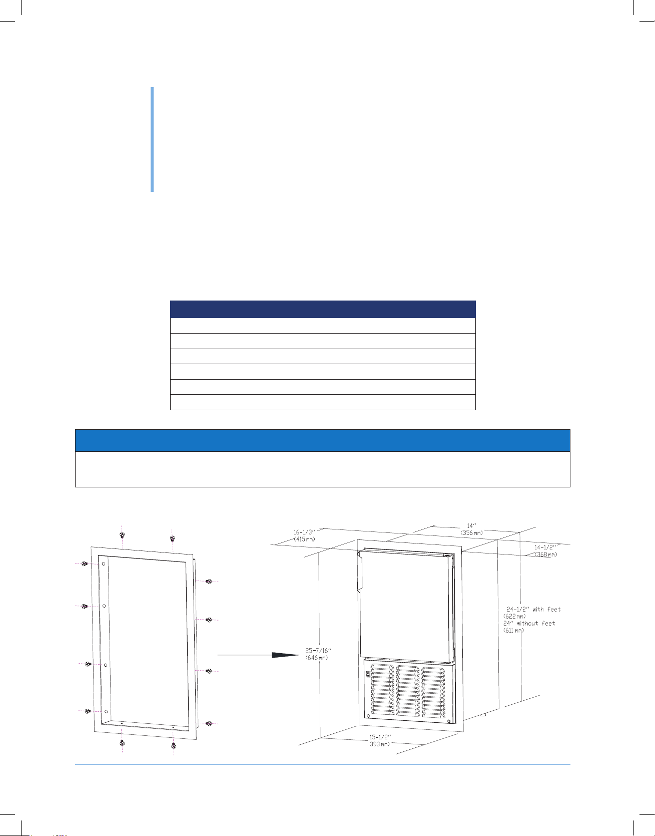
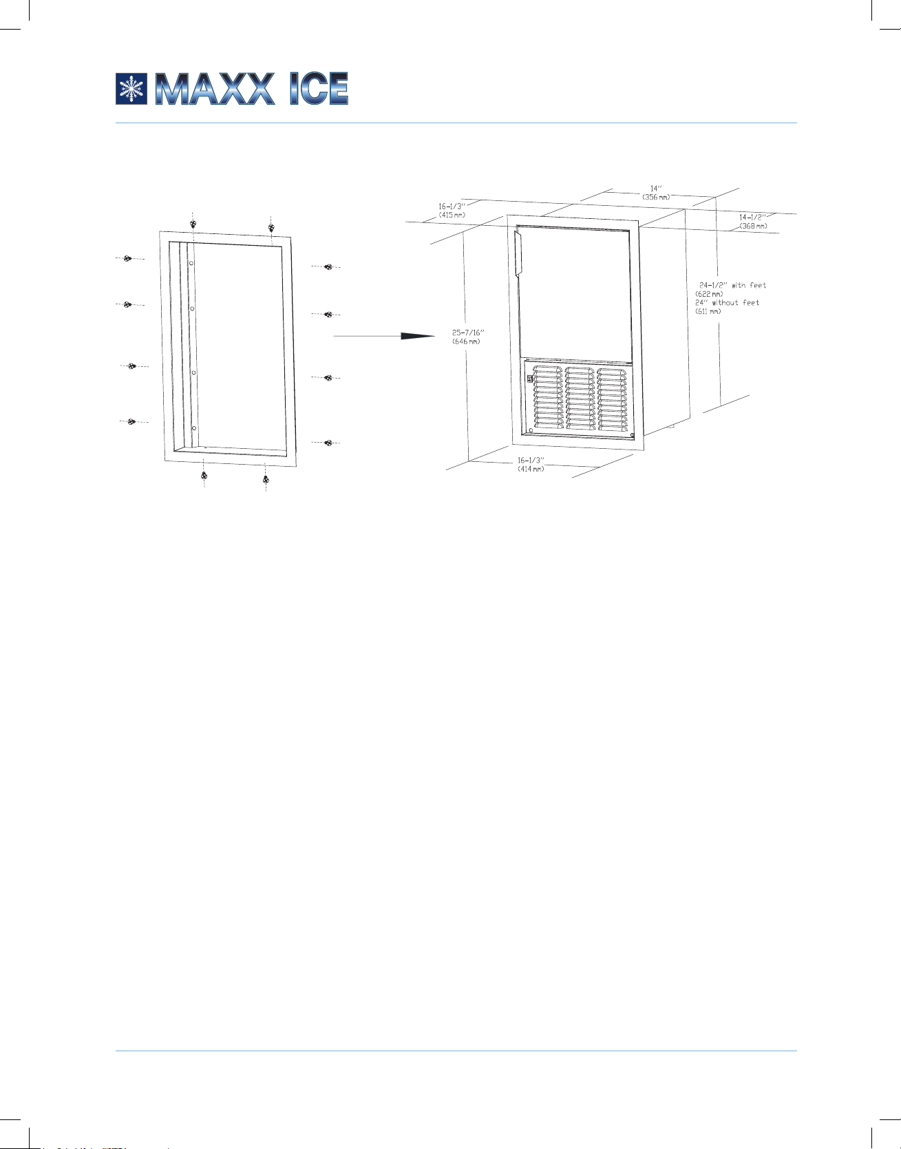
BUILT-IN INSTALLATION
WARNING
DO NOT install in spaces containing gasoline engines, fuel tanks or fuel line ttings. This
device does not meet federal requirement for ignition protection. Failure to comply could
result in injury or death.
A built-in installation will allow you to install the ice maker under a counter or in a kitchen cabinet
provided the required clearance space around the ice maker is respected.
Location requirements:
Required Cabinet Opening : 14-1/4”(362 mm) W x 24-5/8” (626 mm) H (FLUSH TO CABINET)
15-1/8”(384 mm) W x 24-5/8” (626 mm) H (FLUSH TO DOOR)
12
Page 13

INSTALLATION INSTRUCTIONS
© 2019 The Legacy Companies
Crescent Ice Maker Instruction Manual
h
(626 mm
Cutout
Height
(626 mm
Cutout Depth
Flush to Cabinet (FTC)
Filler Panel ˄Not Provided by Orien˅Needed to attach Mounting Flange on Unit
See Electrical
Specifications
for Power Supply
Cutout
Height
24-5/8"
)
or No Flanges
Preferred location
for water line and
electrical outlet is
in adjacent
cabinet.
7"
(178 mm)
4"
(102 mm)
5/8"
(16 mm)
16-1/2"
(420 mm)
Cutout Dept
Flush to Door (FTD)
Filler Panel ˄Not Provided by Orien˅Needed to attach Mounting Flange on Unit
See Electrical
Specifications
for Power Supply
24-5/8"
)
Preferred location
for water line and
electrical outlet is
in adjacent
cabinet.
7"
(178 mm)
4"
(102 mm)
5/8"
(16 mm)
18-3/8"
(466 mm)
3/4"
(18 mm)
Minimum Flange
Mounting Area
14-1/4"
(362 mm)
Cutout Width
3/4"
(18 mm)
Minimum Flange
Mounting Area
3/4"
(18 mm)
Minimum Flange
Mounting Area
15-1/8"
(384 mm)
Cutout Width
3/4"
(18 mm)
Minimum Flange
Mounting Area
A built-in installation requires 2” (5 cm) or more behind the unit for water line and plug clearance for
proper operation. Built-in units are designed for zero clearance at the top and each side of the unit.
Fan-forced condenser cooling is used. This requires air circulation through the lower section of the
unit.
NOTICE
• If rubber feet are removed from the bottom of the unit, the mounting screws must be reinstalled
into the bottom of the cabinet to avoid damage to components mounted to the base pan.
• The air path for exhaust and fresh air intake must be unrestricted! Recirculation between fresh
air intake and exhaust air must be prevented.
• Anyrestrictionofairoworventilationwilldisruptnormaloperationoftheunit,resultingin
damage components, and voids warranty.
• Connect to potable water supply only.
13
Page 14

INSTALLATION INSTRUCTIONS
© 2019 The Legacy Companies
Crescent Ice Maker Instruction Manual
ELECTRICAL CONNECTION
Do not, under any circumstances, cut or remove the third (ground) prong from the power cord.
For personal safety, this appliance must be properly grounded. The power cord of this appliance is
equipped with a 3-prong grounding plug that mates with a standard 3-prong grounding wall outlet to
minimize the possibility of electric shock hazard from the appliance. Have the wall outlet and circuit
checked by a qualied electrician to make sure the outlet is properly grounded. When a standard
2-prong wall outlet is encountered, it is your responsibility and obligation to have it replaced with a
properly grounded 3-prong wall outlet.
The ice maker should always be plugged into its own individual electrical outlet. The outlet must have
a voltage rating that matches the rating label on the appliance. This provides the best performance
and also prevents overloading boat wiring circuits, which could cause a re hazard from overheated
wires. Never unplug your ice maker by pulling on the power cord. Always grip the plug rmly and pull
straight out from the outlet. Repair or replace immediately all power cords that have become frayed or
otherwise damaged. Do not use a cord that shows cracks or abrasion damage along its length or at
either end. When moving the ice maker, be careful not to damage the power cord.
If the supply cord is damaged, it must be replaced by the manufacturer, its service agent, or similarly
qualied persons in order to avoid a hazard.
The 110V model has a xed power cord with NEMA 5-15P power plug. The 220V model has a
detachable power cord and has 4 options for a power plug.
DESCRIPTION
Power Cord 220 - 240V Great Britain/Ireland
Power Cord 220 - 240V Australia/New Zealand/China
Power Cord 220 - 240V Continental Europe
Power Cord 220 - 240V India
EXTENSION CORD
Because of potential safety hazards under certain conditions, it is strongly recommended that you do
not use an extension cord with this ice maker.
THE MANUFACTURER DISCLAIMS ANY RESPONSIBILITY IF THE ABOVE INSTRUCTIONS ARE
NOT FOLLOWED.
14
Page 15
INSTALLATION INSTRUCTIONS
© 2019 The Legacy Companies
Crescent Ice Maker Instruction Manual
WATER SUPPLY
1. Turn off the main water supply. Turn on the nearest faucet long enough to clear a line of water.
2. Find a 1/2" to 3/4" vertical cold water pipe near the installation location. The distance should be
less than 9 feet.
3. A shut-off valve must be installed to the main water supply. If the water pipe has a plain piece of
copper tubing, attach a 1/4" O.D. compression union to the tubing and remove the nut.
4. Thread the nuts of the supplied water supply hose to the tap and water inlet valve. Tighten rmly
by hand, then one-half turn with a wrench.
5. Turn on the main water supply and tap. Check for water supply connection leaks. Tighten all
connections.
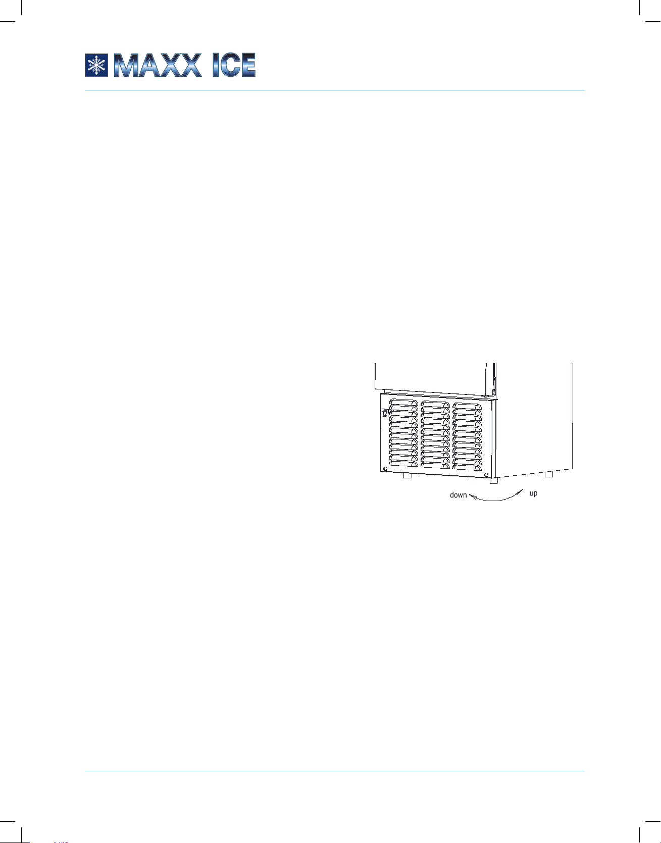
LEVELING THE ICE MAKER
The ice maker must be leveled in order to work properly.
It can be raised or lowered by turning the four feet on the
bottom of the machine. We recommend using a
carpenter’s level to check the machine.
1. Place a carpenter’s level on top of the product to see
if the ice maker is level from front to back and side to
side.
2. Adjust the height of the feet as follows:
• Turn the leveling feet to the right to lower that
side of the ice maker.
• Turn the leveling feet to the left to raise that side of the ice maker.
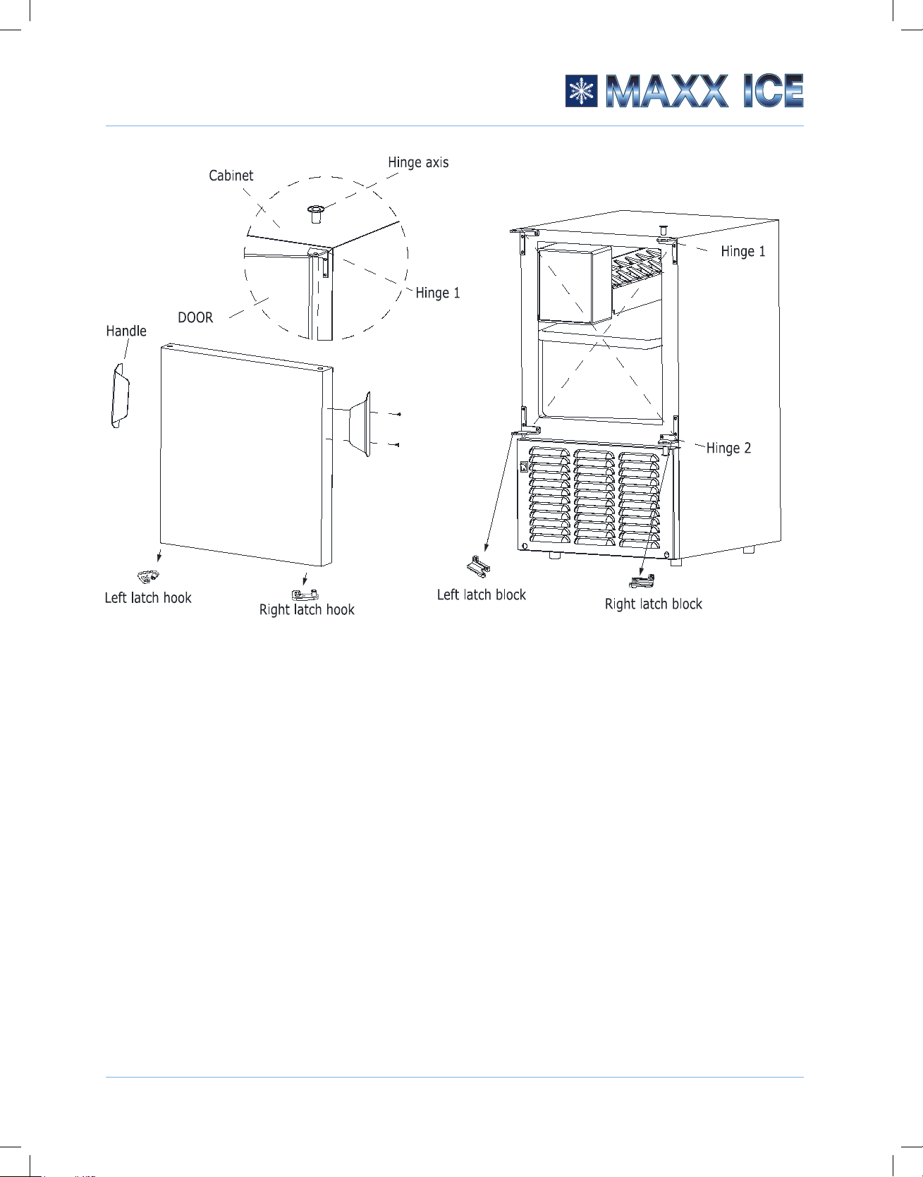
DOOR REVERSAL
This appliance has the capability of the door opening from either the left or right side. The appliance
is delivered to you with the door opening from the left side. Should you desire to reverse the opening
direction, please follow the following reversal instructions.
Tools needed: Flathead screwdriver, Phillips screwdriver.
IMPORTANT: Before you begin, unplug the ice maker or disconnect power.
15
Page 16
INSTALLATION INSTRUCTIONS
© 2019 The Legacy Companies
Crescent Ice Maker Instruction Manual
To remove the door from the hinges:
1. Using a athead screwdriver, separate the hinge axis from Hinge 1. Set aside.
2. Open the door about 20 degrees around the axis of Bottom Hinge 2, then lift the door off Bottom
Hinge 2.
3. Remove the right latch hook located in the right bottom of the door and the plastic cap located in
the left bottom of the door.
4. Install the left latch hook (in the accessory bag) to the left bottom of the door where the plastic cap
was placed and put the plastic cap on the other side.
16
Page 17

INSTALLATION INSTRUCTIONS
© 2019 The Legacy Companies
Crescent Ice Maker Instruction Manual
To replace the door on the hinges:
1. Using a athead screwdriver, remove the plug buttons from the screw holes opposite the door
hinges, top, and bottom. Set aside.
2. Replace the axis on the Hinge 1 and tighten it rmly. Remove Hinge 1 and install it with the left
latch block (in the accessory bag) on the opposite bottom side.
3. Remove Hinge 2 and take down the right latch block. Place Hinge 2 on the opposite top side.
Separate the axis from Hinge 2 and set it aside.
4. Align the door on Bottom Hinge 1 and replace the axis on Hinge 2. Tighten it rmly. Place the
handle on the other side.
5. Push the plug buttons into the original screw holes.
6. Swap the door handle.
17
Page 18
© 2019 The Legacy Companies
Crescent Ice Maker Instruction Manual
OPERATING
INSTRUCTIONS
5
ICE MAKING INSTRUCTIONS
1. Turn the unit on by pressing the Power button.
2. Water will be pumped from the water valve to the ice maker tray for freezing. The rst cubes may
be small because of air in the water line. Later cubes will be of standard crescent-type size.
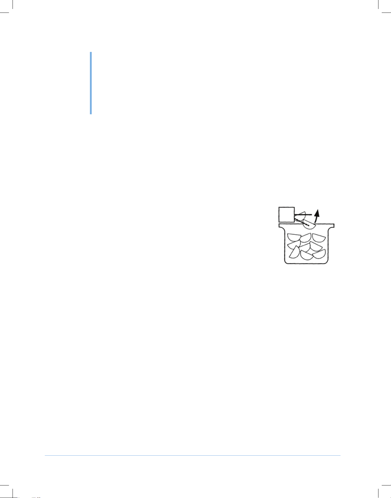
3. Once the freezing process is complete, the ice shovel will turn and push the ice cubes down to the
ice basket.
• NOTE: Although the unit has been tested and cleaned at the factory,
due to long-term transit and storage, discard all ice cubes made
during the rst 3 hours of operation.
• When the ice bucket is full, the ice maker tray will automatically
shut off. When ice cubes are melted or removed, the ice maker will
resume its operation.
• Ice delivery may be interrupted by raising the metal arm into an
upright position.
• If the ice maker is not used regularly, it is recommended that the ice bucket be emptied
periodically to ensure ice freshness.
• Sometimes the ice cubes may appear cloudy. This appearance is due to the rapid freezing
of the ice cube. This cloudiness is trapped air in the water and does not affect the taste and
quality of the ice.
• The air intake and exhaust should be kept free of dust and lint to allow free airow.
• This unit should be defrosted approximately every 4-6 weeks or when frost on the ice maker
wall is excessive or 1/4” thick. To defrost, turn the unit off, remove the ice cubes, and keep the
ice maker door open at least two inches.
• Do not place cans or bottles in the ice compartment because they will freeze.
• Never turn the water supply tap off when the ice maker is working.
• Never touch the evaporator when the unit is running.
• Keep the ice maker door closed to reduce melting and to ensure proper ice formation.
18
Page 19

OPERATING INSTRUCTIONS
© 2019 The Legacy Companies
Crescent Ice Maker Instruction Manual
!
NORMAL SOUNDS
Your new ice maker may make sounds that are not familiar to you. Hard surfaces like the oor and
walls can make the sounds seem louder than they actually are. The following describes the kinds of
sounds that might be new to you and what may be making them.
• Rattling noises may come from the ow of the refrigerant or the water line. Items stored on top of
the ice maker can also make noises.
• The high-efciency compressor may make a pulsating or high-pitched sound.
• Water running from the evaporator to the water reservoir may make a splashing sound.
• As each cycle ends, you may hear a gurgling sound due to the refrigerant owing in your ice
maker.
• You may hear air being forced over the condenser by the condenser fan.
• During the harvest cycle, you may hear the sound of ice cubes falling into the ice basket.
POWER FAILURE
Most power failures are corrected within a few hours and should not affect the temperature of your ice
maker if you minimize the number of times the ice maker cover is opened. If the power is going to be
off for a longer period of time, take the proper steps to disconnect your appliance.
WARNING
Failure to unplug the ice maker could result in electrical shock or personal injury.
19
Page 20
© 2019 The Legacy Companies
Crescent Ice Maker Instruction Manual
FLANGE KIT
INSTALLATION
6
The ange kits are optional accessories and are sold separately.
The ange kits allow seamless installation of the MMAR25 Series, which gives a greater degree of
personalized application. They are optional accessories sold separately. The ange kit is used for a
consistent, smooth surface and additional secure fastening by screwing the ange to the cabinet.
DESCRIPTION
SS Flange Kit for Flush to Door Installation
SS Flange Kit for Flush to Cabinet Installation
Black Flange Kit for Flush to Door Installation
Black Flange Kit for Flush to Cabinet Installation
White Flange Kit for Flush to Door Installation
White Flange Kit for Flush to Cabinet Installation
NOTICE
Theangemustnotbeusedforsupportingtheweightoftheunit.Adjustthefeettoleveltheunit
andensuretheloweredgeoftheangedoesnottouchtheground.
FLUSH TO CABINET:
20
Page 21
FLANGE KIT INSTALLATION
© 2019 The Legacy Companies
Crescent Ice Maker Instruction Manual
FLUSH TO DOOR:
INSTALLATION
1. Remove the ange and screws from the shipping carton.
2. Using a athead screwdriver, carefully remove the pre-installed decorative plugs from the screw
holes located on the top, left, and right panels of the ice maker.
3. Put the ange through the front of the ice maker on the cabinet.
4. Adjust the feet to make sure the ange does NOT touch the ground.
5. Align the ange squarely with the unit. Screw the ange tight with the cabinet of the ice maker.
6. Move the ice maker with the ange to the cabinet. The ice maker must sit on a level surface.
7. Screw the ange to the kitchen cabinet if the ice maker is installed in a moving environment for
anti-shock installation.
21
Page 22

© 2019 The Legacy Companies
Crescent Ice Maker Instruction Manual
CARE AND
MAINTENANCE
!
7
Always disconnect power at the source before working on the unit. Failure to unplug the
ice maker could result in electrical shock or personal injury.
• Do not touch the power plug when your hands are wet.
• Never unplug the unit by pulling on the cord. Grasp the plug and pull out rmly.
WARNING
CLEANING AND MAINTENANCE
Periodic cleaning and proper maintenance will ensure efciency, top performance, and long life. The
maintenance intervals listed are based on normal conditions. You may want to shorten the intervals if
you have pets, or if there are other special considerations.
• Periodically vacuum dust and dirt from the condenser, which is located behind the grill at the
bottom front of the unit.
• Regularly inspect plumbing connections to ensure that no leaks are present.
• Disconnect the water supply hose if the ice maker will not be used for a long period of time.
• Never keep anything in the ice storage bin that is not ice. Objects such as wine and beer bottles
are not sanitary.
EXTERIOR CLEANING
The door and cabinet may be cleaned with a mild detergent and warm water solution such as 1
oz. (28 g) of dish-washing liquid mixed with 2 gallons of warm water. Do not use solvent-based or
abrasive cleaners. Use a soft sponge and rinse with clean water. Wipe with a soft, clean towel to
prevent water spotting.
Clean stainless steel with a mild detergent and warm water solution and a damp cloth. Never use an
abrasive cleaning agent.
22
Page 23

CARE AND MAINTENANCE
© 2019 The Legacy Companies
Crescent Ice Maker Instruction Manual
!
INTERIOR CLEANING
When necessary, defrost and thoroughly clean the inside of the unit with mild soap and water. Do not
use electrical heating devices or sharp or pointed tools when defrosting.
When defrosting or leaving the unit turned off, leave the door open.
This allows air to dry the inside of the cabinet, reducing the chance for mildew and damage to the
mold mechanism’s components.
WINTERIZING
WARNING
Always disconnect power at the source before working on the unit. Do not winterize this
unit with ANY type of anti-freeze; damage to the mold coating will occur, invalidating
product’s Limited Warranty and creating potential health hazard.
1. Shut off the water supply to the unit.
2. Remove the front grill and disconnect the water supply connector. Remove the white plastic tubing
and nut from the bottom of the solenoid valve.
3. Turn the power on. Allow the unit to run for an hour. Remove any cubes that may have been
ejected during this period. Turn off power and open the door to allow the inside to defrost. After it
has defrosted, wipe it dry and leave the door open.
RECOMMISSIONING
Connect the water supply lines, turn on the water, check for leaks, then restore power to the unit.
After initial cooldown of 45-60 minutes, the unit will cycle approximately every 40 minutes.
START-UP
Turn on the water, check for leaks, and then turn on power. Turn on the unit by pressing the Power
button. The fan and compressor will normally turn on immediately, resulting in air circulation through
the grill and a faint hum from the compressor. If the machine was shut off while in the ice-harvesting
cycle, it will have to complete the cycle before the compressor and the fan will turn on (approximately
5 minutes). The interior temperature will drop below freezing. The rst harvest of ice should occur
within 60 minutes of start-up. After the lines are purged of air, normal harvesting and relling occur
every 40 minutes or less, under normal conditions.
23
Page 24

CARE AND MAINTENANCE
© 2019 The Legacy Companies
Crescent Ice Maker Instruction Manual
!
CONDENSER CLEANING
WARNING
DO NOT touch the condenser surface. The surface is sharp and can be easily damaged.
A dirty or clogged condenser prevents proper airow, reduces ice-
making capacity, and causes higher-than-recommended
operating temperatures that may lead to component failure. Have
the condenser cleaned at least once every six months.
1. Unplug the ice maker or disconnect power.
2. Remove the two screws on the front cover and gently pull the
cover off.
3. Remove dirt and lint from the condenser and the unit
compartment with the brush attachment of a vacuum cleaner.
4. Reassemble the front cover.
5. Plug in the ice maker or reconnect power.
24
Page 25

© 2019 The Legacy Companies
Crescent Ice Maker Instruction Manual
TROUBLESHOOTING
8
PROBLEM POSSIBLE CAUSES SOLUTIONS
• The machine won't operate. • The ice maker is unplugged.
• The ice maker power switch is
OFF.
• The ice storage bin is full of ice.
• The compressor works
abnormally with a buzzing noise.
• The water doesn't feed in after
the ice maker starts.
• Machine makes ice, but bin does
not ll up with ice.
• Water is leaking out of the unit. • A few water droplets are on the
• Cubes are partially formed and
are white at the bottom.
• Noise during operation. • The feet are not leveled and
• The voltage is lower than
recommended.
• The water supply tap is turned
off.
• The water supply pipe is not
properly connected.
• The condenser may be dirty.
• The airow to the ice maker may
be obstructed.
• The ambient temperature and
water temperature are high, or it
is near with some heat source.
door.
• The water supply connection is
leaking.
• There is not enough water in the
water bin.
locked.
• Certain sounds are normal.
• Plug the ice maker in.
• Turn the ice maker power switch
to ICE (ON).
• Take away some ice cubes; make
sure the “ice full” probe is free of
ice.
• Stop the ice maker and do not
restart until the voltage is normal.
• Turn on the water supply tap.
• Reconnect the water supply pipe.
• Clean the condenser.
• Check the installation.
• Run the unit for a longer period
of time.
• Under some conditions, humidity
may condense on the door.
Consider moving the unit or just
be more careful when you open
the door.
• Tighten water supply hose tting.
• Check if the water supply
pressure is below 15 psi.
• Check the water supply. It may be
restricted.
• Check for a water leak at the
water trough.
• Level the feet. See “Leveling the
Ice Maker” on page 15.
• See “Normal Sounds” on page 19.
25
Page 26

TROUBLESHOOTING
© 2019 The Legacy Companies
Crescent Ice Maker Instruction Manual
PROBLEM POSSIBLE CAUSES SOLUTIONS
• The ice made is too large and has
pieces sticking together.
• Conditions for ice-making cycle
are right but no ice is made.
• The ice maker stops suddenly
while making ice.
• The body of the ice maker is
electried.
• Scale builds up quickly inside the
machine.
• The water temperature in the
storage tray or ambient is too low.
• The refrigerant leaks and/or the
sealed system is blocked.
• Water pressure is not properly
set.
• The electricity is off.
• The room temperature is out of
the stated range.
• The ground line is not in the
sockets.
• The calcium level in the water is
too high.
• Stop the machine and reset the
ice-making cycle.
• Restart the machine after turning
it off.
• Contact MAXX ICE Service
Department.
• The recommended water
pressure is 58 psi. Pressures
must not fall below 15 psi and
static pressure must not exceed
80 psi.
• Reconnect the power supply line.
• Cut off the electricity and let the
ice maker stop working until the
temperature returns within the
stated range.
• Use the correct plug and outlet.
• Use a water-softening apparatus
installed in front of the water inlet
valve.
For Technical Service, call 1-877-368-2797, 24 hours 7 days a week, U.S. and Canada.
26
Page 27
© 2019 The Legacy Companies
Crescent Ice Maker Instruction Manual
PARTS INFORMATION
9
Flanges (optional parts)
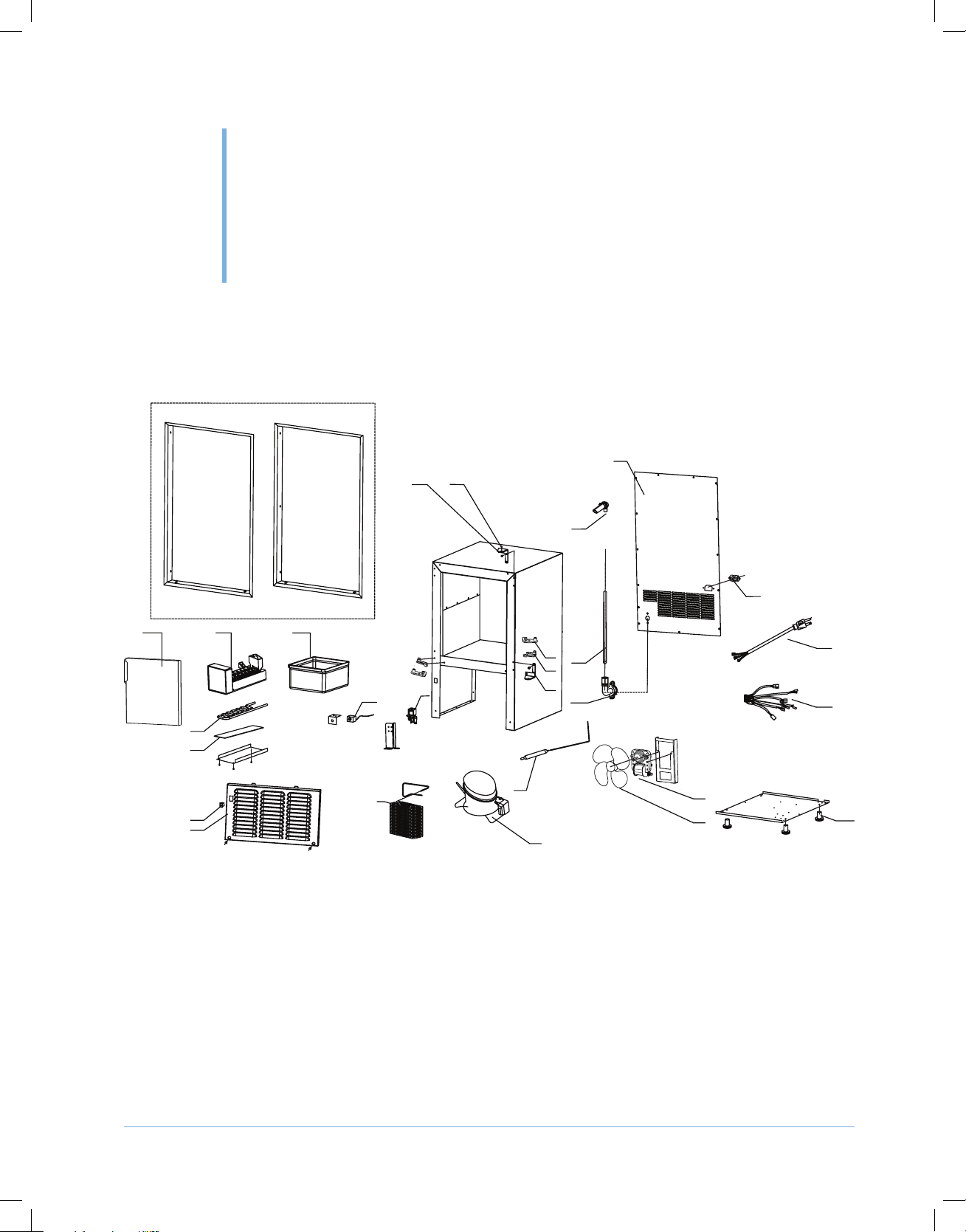
EXPLODED VIEW
14
7
6
11
28 29
1
3
4
26
27
15
2
5
8
12
9
24
23
25
10
13
21
22
19
20
16
17
18
27
Page 28

PARTS INFORMATION
© 2019 The Legacy Companies
Crescent Ice Maker Instruction Manual
PARTS LIST
ITEM
NO.
10 Bottom Hinge 1860418600 1860418600 1860418600 1860418600 1860418600 1860418600
11 Water Injector 1861532100 1861532100 1861532100 1861532100 1861532100 1861532100
12 Water Inlet Pipe 1811206006 1811206006 1811206006 1811206006 1811206006 1811206006
13 Water Inlet 1864526301 1864526301 1864526301 1864526301 1864526301 1864526301
14 Rear Plate 1860131900 1860131900 1860131900 1860132000 1860132000 1860132000
15 Power Plug Coupler N/A N/A N/A 1854400000 1854400000 1854400000
16 Power Cord 1853113802 1853113802 1853113802 N/A N/A N/A
17 Wire Harness 1851764504 1851764504 1851764504 1851701900 1851701900 1851701900
18 Feet 1864811100 1864811100 1864811100 1864811100 1864811100 1864811100
19 Fan 1858204600 1858204600 1858204600 1858204500 1858204500 1858204500
20 Fan Blade 1860701500 1860701500 1860701500 1860701500 1860701500 1860701500
21 Dray Filter 1880007800 1880007800 1880007800 1880007800 1880007800 1880007800
22 Compressor 1858421500 1858421500 1858421500 1858421600 1858421600 1858421600
22.1 Starting Relay 1858421510 1858421510 1858421510 1858421610 1858421610 1858421610
22.2 Overload Protector 185824520 185824520 185824520 185824520 185824520 185824520
23 Water Inlet Valve 1854707300 1854707300 1854707300 1854707400 1854707400 1854707400
24 Thermostate 1849740700 1849740700 1849740700 1849740700 1849740700 1849740700
25 Condensor 1885001003 1885001003 1885001003 1885001003 1885001003 1885001003
26 Power Switch 1854002201 1854002201 1854002201 1854002201 1854002201 1854002201
27 Louver 1860443600 1860443700 1860443800 1860443600 1860443700 1860443800
28 MMARFTDFLG-S SS Flange Kit for Flush to Door
29 MMARFTCFLG-S SS Flange Kit for Flush to Cabinet
DESCRIPTION MMAR25S MMAR25B MMAR25W MMAR25S[E0] MMAR25B[E0] MMAR25W[E0]
1 Door 1860131600 1860131700 1860131800 1860131600 1860131700 1860131800
2 Ice Maker Module 1861509600 1861509600 1861509600 1861507101 1861507101 1861507101
3 Evaporator 1880028901 1880028901 1880028901 1880028901 1880028901 1880028901
4 Thermal Gasket 1815208800 1815208800 1815208800 1815208800 1815208800 1815208800
5 Ice Bin 1864810600 1864810600 1864810600 1864810600 1864810600 1864810600
6 Top Hinge 1860418500 1860418500 1860418500 1860418500 1860418500 1860418500
7 Hinge Pin 1864311200 1864311200 1864311200 1864311200 1864311200 1864311200
8 Right Hatch Hook 1810173500 1810173500 1810173500 1810173500 1810173500 1810173500
9 Right Door Hatch 1810173400 1810173400 1810173400 1810173400 1810173400 1810173400
8 Left Hatch Hook 1810173300 1810173300 1810173300 1810173300 1810173300 1810173300
9 Left Door Hatch 1810173200 1810173200 1810173200 1810173200 1810173200 1810173200
MMARPLUG-G N/A N/A N/A 1853117600 1853117600 1853117600
MMARPLUG-I N/A N/A N/A 1853117700 1853117700 1853117700
MMARPLUG-F N/A N/A N/A 1853117800 1853117800 1853117800
MMARPLUG-D N/A N/A N/A 1853118000 1853118000 1853118000
MMARFTDFLG-B Black Flange Kit for Flush to Door
MMARFTDFLG-W White Flange Kit for Flush to Door
MMARFTCFLG-B Black Flange Kit for Flush to Cabinet
MMARFTCFLG-W White Flange Kit for Flush to Cabinet
28
Page 29

© 2019 The Legacy Companies
Crescent Ice Maker Instruction Manual
WARRANTY
THE LEGACY COMPANIES WARRANTY COVERAGE
MAXX ICE MARINE MMAR25 MARINE LIMITED WARRANTY
THE LEGACY COMPANIES (TLC) warrants to each Retail Buyer that its products be free from
defects in materials and workmanship for the period specied below. THE LEGACY COMPANIES
obligation under this warranty shall be limited to repairing or replacing, at its option, any part or
product found to be defective within the specied warranty period.
2-YEAR LIMITED WARRANTY
For two years from the date of original purchase, this product warranty covers all parts and labor to
repair or replace any part of the product that proves to be defective in materials or workmanship.
5-YEAR SEALED SYSTEM WARRANTY
For ve years from the date of original purchase, Maxx Marine will repair or replace the following
parts, labor not included, that prove to be defective in materials or workmanship: compressor,
condenser, evaporator, drier, and all connecting tubing.*
*May or may not be serviced on site. Unit may be replaced in kind or returned to the factory for repair
at the sole discretion of THE LEGACY COMPANIES based on the apparent condition of the unit and
its needed servicing. Warranty subject to verication by THE LEGACY COMPANIES.
WARRANTY CLAIMS
Warranty claims can be made by calling 1-877-368-2797 during normal business hours between
8:30am and 5:30pm Eastern, Monday through Friday excluding Weekends and Holidays. Emergency
warranty service claims can be made after hours, weekends and holidays by dialing 1-877-3682797 and following the automated prompts. All claims must include: make, model number, serial
number, proof of purchase (dated receipt), date of installation, retail store where purchased and all
pertinent information supporting the claim prior to the issuance of a warranty claim number. At the
time of a warranty claim, should on-site service be necessary, a service company will be dispatched
to the location to facilitate repairs covering labor (during normal business hours, premium or overtime
service is not included) and travel up to 50 miles from location. If during the warranty event the
on-site technician determines the issue to be the result of improper installation, misuse, abuse,
or requires adjustments and/or calibration, the end user will become responsible for any charges
brought forth by the service company. Should on-site service not be required, an RMA (Return
Merchandise Authorization) may be issued. The issuance of an RMA requires the end user provide
29
Page 30

WARRANTY
© 2019 The Legacy Companies
Crescent Ice Maker Instruction Manual
adequate packaging and shipping including the cost of freight to the Service Center for disposition.
Should a replacement unit be necessary, it will be at the sole discretion of Management and a new or
refurbished unit will be provided. The cost to repair or replace the item including the cost to ship the
unit back to the end user will be covered as a part of the warranty.
PRODUCT RETURNS
Product returned without our RMA or to the retailer under the auspices of warranty, freight damage or
other, prior to the review and authorization of Management with the expectation of receiving a credit
and/or payment for the same, is strictly prohibited and will become the sole responsibility of the party
authorizing the transaction.
WARRANTY EXCLUSIONS
NO CONSEQUENTIAL DAMAGES: The manufacturer is not responsible for economic loss or
special, indirect or consequential loss including without limitation; loss or damage arising from food or
product spoilage claims, whether or not on account of product failure.
CONSEQUENTIAL DAMAGES: This warranty does not cover any defect due to, or resulting from,
ordinary wear and tear, handling, abuse, misuse, improper ventilation, erratic utility service or harsh
chemical action, nor shall it extend to any product from which the serial number has been removed
or altered, or modications made by unauthorized service personnel or damage by ood, re or other
acts of God.
WARRANTY IS NOT TRANSFERABLE: This warranty is not transferable or assignable and applies
only to the original veried purchaser.
NO IMPLIED WARRANTY OF MERCHANTABILITY OR FITNESS FOR PARTICULAR SERVICE:
There are no other warranties statutory, expressed, or implied, except that which is specically found
on the website. These warranties are exclusive and in lieu of all other warranties including implied
and merchantability or tness of a particular purpose.
IMPROPER ELECTRICAL CONNECTIONS: The manufacturer is not responsible for the repair or
replacement of failed or damaged components resulting from electrical power failure, the use of
extension cords, low voltage, or voltage drops to the unit.
IMPROPER USAGE: The manufacturer assumes no liability for parts or labor coverage for
component failure or other damages resulting from improper usage or installation or failure to clean
and/or maintain the product as set forth in the Owner’s Manual provided with each unit.
ADJUSTMENTS & CALIBRATIONS: Adjustments including calibrations, leveling, tightening of
fasteners, or utility connections normally associated with the original installation are the responsibility
of the retailer or installer and not the responsibility of the manufacturer.
CONSEQUENTIAL DAMAGES: This warranty does not cover any defect due to, or resulting from,
ordinary wear and tear, handling, abuse, misuse, improper ventilation, or harsh chemical action,
nor shall it extend to any product from which the serial number has been removed or altered, or
modications made by unauthorized service personnel or damage by ood, re or other acts of God.
30
Page 31

WARRANTY
© 2019 The Legacy Companies
Crescent Ice Maker Instruction Manual
OUTSIDE NORTH AMERICA: This warranty does not apply to, and the manufacturer is not
responsible for any warranty claims made on products sold or used outside North America and or any
territories of the United States of America.
DISCLAIMER
The Manufacturer reserves the exclusive right to change or modify this warranty statement or any
part herein at any time and without prior notice.
07/01/2019
P/N: 1866826800
31
Page 32

The Legacy Companies
2255 Enterprise Avenue, Suite 160, Fort Lauderdale, FL 33331
Sales: (954) 202-7419 • Sales@TheLegacyCompanies.com
Tech Service: (877) 368-2797 • Service@MaxxHelp.com
07/19
www.MaxximumFoodService.com
 Loading...