

Maxxair MAXXFAN Plus 4700N, MAXXFAN Plus 4900N Instructions Manual

INSTALLATION INSTRUCTIONS,
INFORMATION AND OPERATING GUIDE
FOR MAXXFAN® Plus MODELS
4700N and 4900N
WARNING! To reduce risk of re, injury to persons or damage to property, use only
in the manner intended by AIRXCEL, INC. Should you have questions, please contact
AIRXCEL/MAXXAIR VENTILATION SOLUTIONS Customer Service at 316.832.3400.
P/N: 11E90000N
02-2018
READ AND SAVE THESE INSTRUCTIONS
NOTE: Refer to Installation Instructions, Information and Operation Guides regarding the
model you have purchased.
The MAXXFAN installs into a standard RV roof opening of 14 by 14 inches.
To determine if your roof opening is correctly sized, simply remove the interior ceiling garnish
trim ring of your existing roof vent and measure the ceiling opening or verify the opening is
large enough by sliding the MAXXFAN interior Garnish trim ring into the opening.
The MAXXFAN is designed for a minimum roof thickness of 2 inches to a maximum of
6 1/2 inches. If your roof thickness is less than 2 inches, build additional thickness at the
ceiling opening using wood or other suitable material.
The MAXXFAN requires a minimum 12 Volt DC, 5 amp service. Conrm that the circuit
you intend to use will accommodate the additional load. Use the proper gauge stranded
wire for electrical connections.
MAXXFAN
®
STEP 1
MAXXFAN requires a 14” x 14” roof
opening, if you are replacing another type
already installed, remove the old existing
roof vent. Remove all old roof sealant for
a minimum of 2” entirely around the roof
opening.
Place the MAXXFAN into the roof opening
and trace a pencil line around it to verify the
clean seal area that will be required. Note
that the MAXXFAN must be centered in
the roof opening with the hinge of the lid
facing the front of the vehicle.
CAUTION: When installing your MAXXFAN, only
use a caulking/sealant compatible with the ange
(plastic product) and the roof surface. DO NOT
use materials containing solvents such as or similar
to Xylene, Toluene, Methyl Ethyl Ketone, Acetate
or Acetone as they can damage the ange. Also,
Polysulde (Thiokol) type sealants must be avoided.
If in doubt, please contact the manufacturer of your
RV for further information.
STEP 2
Prior to installing the MAXXFAN into the
roof opening, apply a continuous strip of
BUTYL tape or equivalent to the underside
of the ange, making sure to cover the
screw holes.
CAUTION: Disconnect main vehicle power before
connecting 12 volt DC power to the MAXXFAN!
STEP 3
Refer to page 4 for network wiring.
STEP 4
Insert the MAXXFAN into the opening with
the lid hinge facing the front of the vehicle and
centering the MAXXFAN in the opening.
Make sure the power wires slide to the interior
and do not become entangled. Using the
sixteen (16) screws provided, screw the
ange to the roof at each raised ring dimple
location along the ange. Screw into the
dimple to pierce the ange, making sure not
to overtighten the screws to avoid cracking the
ange.
STEP 5
After the MAXXFAN has been installed,
remove the excess BUTYL caulk that may
have squeezed out. Using a sealer such
as Dicor self-leveling lap sealant or similar
caulking, apply a daub over every exposed
screw head. In addition, apply a bead
(approximately 3/16”) along the outside edge
of the ange all the way around the vent.
THIS COMPLETES THE ROOF TOP
PORTION OF THE INSTALLATION
NOTE: Re-apply 12 volt vehicle power. This
MAXXFAN incorporates a self-resetting fuse on
the circuit board located in the ceiling assembly. It
can be reset by removing and re-applying power.
If your fan fails to operate or needs reset, contact
Customer Service at 316.832.3400 for assistance
or solicit the aid of an electrical technician.
INSTALLATION INSTRUCTIONS
2
5
4
2

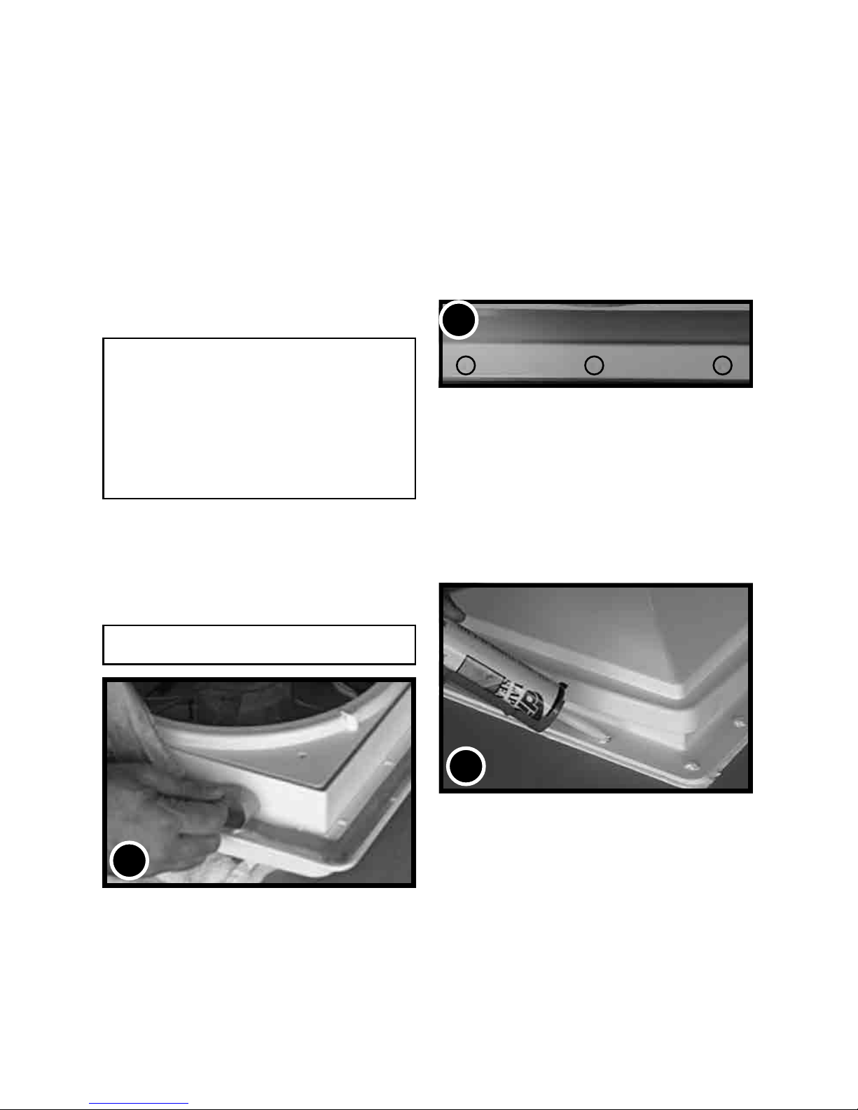
STEP 6
The interior Garnish Trim Ring must be trimmed to t your particular RV roof thickness. To
accomplish this, measure the distance from the vehicle ceiling surface to each corner of the
MAXXFAN Control Plate.
Most RV roofs have some slope, so measuring each corner is necessary. The Garnish ring
should be cut 1/4” to 1/2” longer than the dimensions measured at each corner.
In Picture #6 to the right, the installation measures 3 and 1/2” from the ceiling (this is an example
only) to the Control Plate. After adding 1/2” as in this example, using a ruler, place a mark at
4” on each corner of each side of the Garnish Ring (refer to 6A below). Once marked, draw a
line connecting all 4” markers on the outside of the Garnish ring and trim accordingly (refer to
6B to the right).
STEP 7
Complete the installation by placing any excess
wiring to the inside of the roof opening and sliding
the Garnish Ring into position. Fasten in place by
using the four painted at head screws provided.
NOTE: DO NOT probe or tamper with the thermostat
sensor or IR sensor shown in illustration #6 above.
MEASUREMENTS STATED
IN STEP 6 ARE USED AS AN
EXAMPLE FOR ILLUSTRATION
PURPOSES ONLY
7
CONGRATULATIONS!!!
You have successfully completed the
installation of your new MAXXFAN.
If you have questions, please visit
Airxcel.com or call us at 316-832-3400.
6A
GARNISH RING
6B
GARNISH
RING
6
IR RECEIVER
3 1/2”
CEILING
3
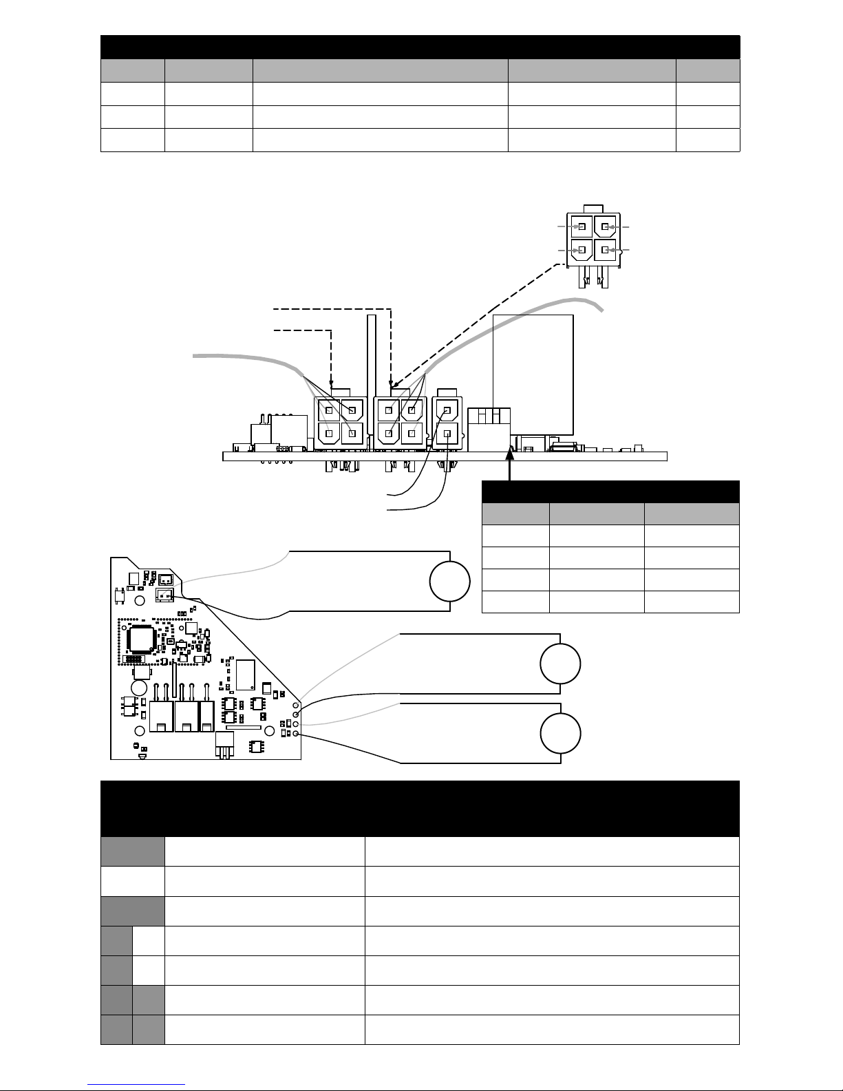
4
J7
J4
J2
ADDRESS NOTES:
The address of the module
can be set using the
Address DIP Switches (if
populated) or the address
can be set by grounding
the pins on J7 (if
populated)
as outlined in the
"ADDRESS CHART"
J2 CAN BUS
J4 CAN BUS
J8
1 - Rain Sensor - Detect
2 - Rain Sensor - GND
Trunk Cable IN
Trunk Cable OUT
Lid Motor Output 2
Lid Motor Output 1
Fan Motor Output 2
Fan Motor Output 1
J5
Dip In 1 (GND)
DIP In 2 (GND)
J7
CAN PINOUT
FOR J2 and J4
2 - CAN L
3 - GND
1 - CAN H
4 - +12V
Lid
Motor
Fan
Motor
Rain
Detector
The CAN network requires
two 120 Ohm terminator
resistors between CAN H
and CAN L.
With both terminators present
the resistance between CAN H
and CAN L should measure
60 Ohms when the network is
powered off.
NET LED STATUS
LED ACTIVITY STATUS
Solid Green Device is connected to network and communicating properly
OFF Device has no power or has completely failed
Solid Red Device has gone oine and is not connected to network
Fast Flashing Green (4times/sec) Device is attempting to make initial connection to network
Slow Flashing Green (1time/sec) Device was online but has not seen a valid network message for 5secs
Alternating Red & Orange Device has gone oine and is attempting to re-connect (within 30secs)
Alternating Green & Orange Device is currently online but has gone oine 2 or more times
MATING CONNECTORS
MFG P/N PIN P/N DESC MATE
Molex 39012040 0039000038, 0039000077, or Similar 4 Pos Mini-Fit Jr J2 & J4
Molex 39012020 0039000038, 0039000077, or Similar 2 Pos Mini-Fit Jr J7
JST XHP-2 SXH-001T-P0.6 or Similar 2 Pos (2.5mm) J8
ADDRESS CHART
ADDRESS DIP IN 1 DIP IN 2
1 OPEN (OFF) OPEN (OFF)
2 GND (ON) OPEN (OFF)
3 OPEN (OFF) GND (ON)
4 GND (ON) GND (ON)
INFORMATION AND OPERATING GUIDE
FOR MAXXFAN® Plus MODELS
4700N and 4900N
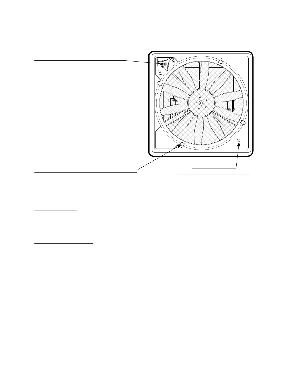
KNOB, VENT LID OPEN/CLOSE
Manual Opening Models
Pull to unlock prior to turning. Rotate Knob
clockwise to Close Vent Lid; Rotate Knob
counter-clockwise to Open Vent Lid. Push
“IN” to lock when Vent Lid is open or closed.
Automatic Opening Models
Allows closing of the vent lid in the event of
RV power loss. This knob does not lock.
Do not push in or pull out. Rotate knob
clockwise to close vent lid; rotate knob
counter-clockwise to open vent lid.
Do not use excessive force when operating
Knob.
INSECT SCREEN RETAINER KNOB
Rotate all 4 knobs 1/2 turn to remove screen.
CAUTION: Never operate fan with screen removed. When removing screen for cleaning, turn
the MAXXFAN OFF and remove the vehicle 12 volt power to the MAXXFAN. When cleaning your
MAXXFAN, use only a mild detergent solution.
RAIN SENSOR - Automatic Models only. If the Rain Sensor circuit detects moisture, it
will TURN OFF the fan and close the lid. Press the FAN ON key to restart the fan after the
Rain Sensor has dried.
CAUTION: If the lid is opened MANUALLY, the RAIN SENSOR will not close the MAXXFAN lid.
CEILING FAN MODE
With the fan motor running, close the Vent Lid to enter Ceiling Fan Mode. The fan motor will
continue to run and circulate air within the RV cabin.
SERIAL NUMBER LABEL
The serial number label is located underneath the round insect screen.
NOTE: The MAXXFAN is designed to be fully opened or fully closed when the vehicle is
moving.
5
THERMOSTAT
TEMPERATURE SENSOR
 Loading...