

Maxxair MAXXFAN Plus 4500K, MAXXFAN Plus 4000K, MAXXFAN Plus 4001K, MAXXFAN Plus 4050K, MAXXFAN Plus 4501K Installation Instructions, Information And Operating Manual
...
INSTALLATION INSTRUCTIONS,
INFORMATION AND OPERATING GUIDE
FOR MAXXFAN® and MAXXFAN® Plus MODELS
4000K • 4001K • 4050K • 4301K • 4401K • 4500K • 4501K • 4801K
WARNING! To reduce risk of re, injury to persons or damage to property, use only
in the manner intended by AIRXCEL, INC. Should you have questions, please contact
AIRXCEL/MAXXAIR VENTILATION SOLUTIONS Customer Service at 316.832.4357.
P/N: 11B90000K
REV B, 01-2016
READ AND SAVE THESE INSTRUCTIONS
NOTE: Refer to Installation Instructions, Information and Operation Guides regarding the
model you have purchased.
The MAXXFAN installs into a standard RV roof opening of 14 by 14 inches.
To determine if your roof opening is correctly sized, simply remove the interior ceiling garnish
trim ring of your existing roof vent and measure the ceiling opening or verify the opening is
large enough by sliding the MAXXFAN interior Garnish trim ring into the opening.
The MAXXFAN is designed for a minimum roof thickness of 2 inches to a maximum of
6 1/2 inches. If your roof thickness is less than 2 inches, build additional thickness at the
ceiling opening using wood or other suitable material.
The MAXXFAN requires a minimum 12 Volt DC, 5 amp service. Conrm that the circuit
you intend to use will accommodate the additional load. Use the proper gauge stranded
wire for electrical connections.
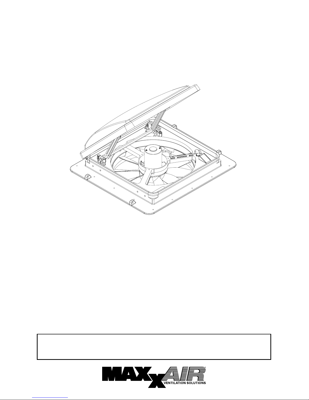
MAXXFAN
®
STEP 1
MAXXFAN requires a 14” x 14” roof opening, if
you are replacing another type already installed,
remove the old existing roof vent. Remove all old
roof sealant for a minimum of 2” entirely around
the roof opening.
Place the MAXXFAN into the roof opening
and trace a pencil line around it to verify the
clean seal area that will be required. Note that
the MAXXFAN must be centered in the roof
opening with the hinge of the lid facing the front
of the vehicle.
CAUTION: When installing your MAXXFAN, only
use a caulking/sealant compatible with the ange
(plastic product) and the roof surface. DO NOT
use materials containing solvents such as or similar
to Xylene, Toluene, Methyl Ethyl Ketone, Acetate
or Acetone as they can damage the ange. Also,
Polysulde (Thiokol) type sealants must be avoided.
If in doubt, please contact the manufacturer of your
RV for further information.
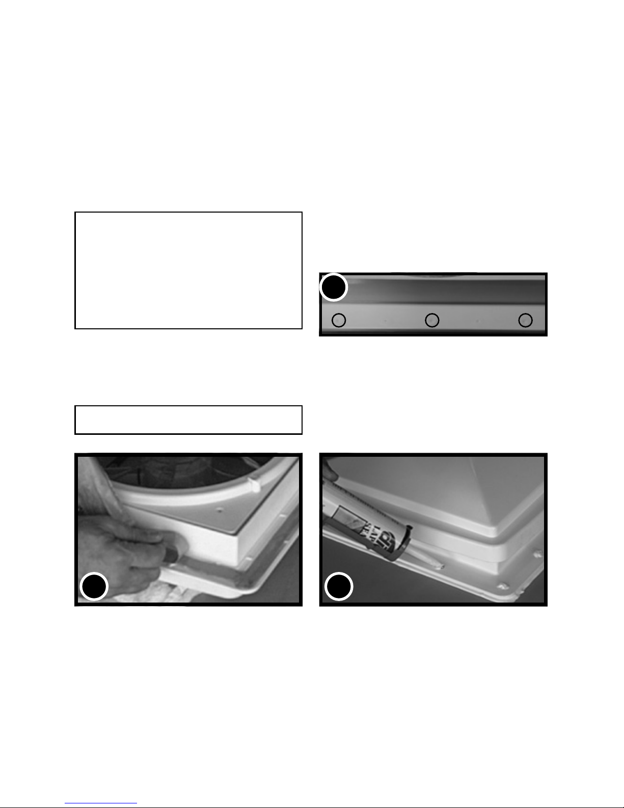
STEP 2
Prior to installing the MAXXFAN into the roof
opening, apply a continuous strip of BUTYL
tape or equivalent to the underside of the ange,
making sure to cover the screw holes.
CAUTION: Disconnect main vehicle power before
connecting 12 volt DC power to the MAXXFAN!
STEP 3
Using the insulated 16 gauge electrical connectors
provided, connect the vehicle’s 12 volt power to
the two MAXXFAN power wires located on the
driver side of the MAXXFAN.
NOTE: The MAXXFAN black wire identied with a tag showing
(+) must be connected to the vehicle 12 volt (+) positive supply.
STEP 4
Insert the MAXXFAN into the opening with the lid
hinge facing the front of the vehicle and centering
the MAXXFAN in the opening. Make sure the
power wires slide to the interior and do not become
entangled. Using the sixteen (16) screws provided,
screw the ange to the roof at each raised ring
dimple location along the ange. Screw into the
dimple to pierce the ange, making sure not to
overtighten the screws to avoid cracking the ange.
STEP 5
After the MAXXFAN has been installed, remove
the excess BUTYL caulk that may have squeezed
out. Using a sealer such as Dicor self-leveling lap
sealant or similar caulking, apply a daub over every
exposed screw head. In addition, apply a bead
(approximately 3/16”) along the outside edge of the
ange all the way around the vent.
THIS COMPLETES THE ROOF TOP PORTION OF THE INSTALLATION
NOTE: Re-apply 12 volt vehicle power. The MAXXFAN, excluding the 4301K and 4401K models, will
emit a beeping sound to indicate power is properly connected. In addition, the Remote Control model
will automatically close the vent cover. If the MAXXFAN does not beep when power is connected, go
back to step #3. Conrm that proper connections were made and 12 volt power is on and available. This
MAXXFAN incorporates a self-resetting fuse on the circuit board located in the ceiling assembly. It can
be reset by removing and re-applying power. If your fan fails to operate or needs reset, contact Customer
Service at 316.832.4357 for assistance or solicit the aid of an electrical technician.
FOR REMOTE CONTROL MODELS: Please refer to the REMOTE CONTROL OPERATING GUIDE
in this manual for use and testing of your remote control. Install two AAA batteries, follow instructions,
aim remote at the ceiling unit and test your fan. The Remote Control comes with a cradle for wall mount
storage of the Handheld Remote Control. Mount the cradle to your wall using the screws provided.
INSTALLATION INSTRUCTIONS - ALL MODELS
2 5
4
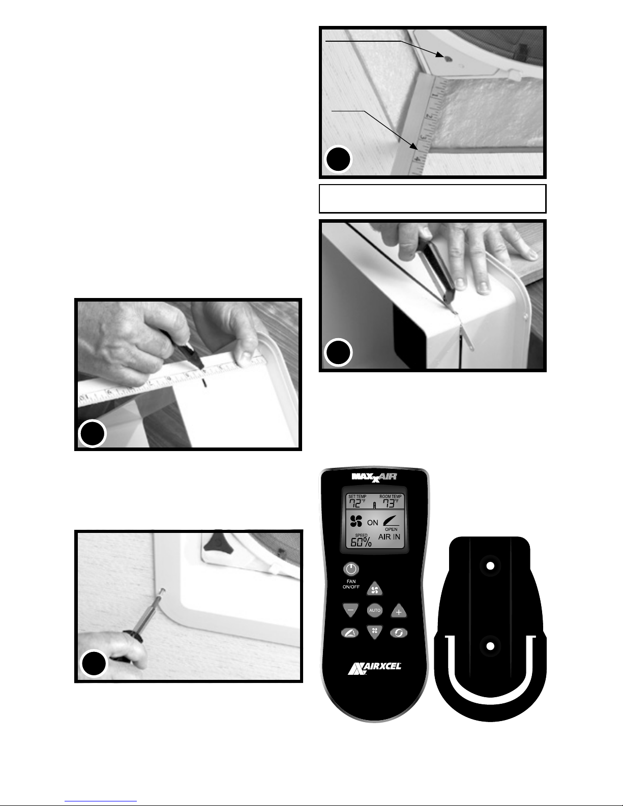
STEP 6
The interior Garnish Trim Ring must be trimmed
to t your particular RV roof thickness. To
accomplish this, measure the distance from
the vehicle ceiling surface to each corner of the
MAXXFAN Control Plate.
Most RV roofs have some slope, so measuring
each corner is necessary. The Garnish ring
should be cut 1/4” to 1/2” longer than the
dimensions measured at each corner.
In Picture #6 to the right, the installation measures
3 and 1/2” from the ceiling (this is an example
only) to the Control Plate. After adding 1/2” as
in this example, using a ruler, place a mark at 4”
on each corner of each side of the Garnish Ring
(refer to 6A below). Once marked, draw a line
connecting all 4” markers on the outside of the
Garnish ring and trim accordingly (refer to 6B to
the right).
STEP 7
Complete the installation by placing any excess
wiring to the inside of the roof opening and sliding
the Garnish Ring into position. Fasten in place by
using the four painted at head screws provided.
NOTE: DO NOT probe or tamper with the thermostat
sensor or IR sensor shown in illustration #6 above.
MEASUREMENTS STATED
IN STEP 6 ARE USED AS AN
EXAMPLE FOR ILLUSTRATION
PURPOSES ONLY
7
CONGRATULATIONS!!!
You have successfully completed the
installation of your new MAXXFAN.
If you have questions, please visit
Airxcel.com or call us at 316-832-4357.
FOR REMOTE CONTROL MODELS:
Attach the included cradle to wall with (2) #6
screws provided. Handheld Remote Control may
be placed into wall cradle for storage.
6A
GARNISH RING
6B
GARNISH
RING
6
IR RECEIVER
3 1/2”
CEILING
 Loading...