

Maxxair MAXXFAN Deluxe 6401K, MAXXFAN Deluxe 5101K, MAXXFAN Deluxe 5301K, MAXXFAN Deluxe 6200K, MAXXFAN Deluxe 7001K Installation Instructions, Information And Operating Manual
...
READ AND SAVE THESE INSTRUCTIONS
NOTE: Refer to supplied Operating Instructions regarding the model you have purchased.
The MAXXFAN installs into a standard RV roof opening of 14” x 14”.
To determine if your roof opening is correctly sized, simply remove the interior ceiling garnish
trim ring of your existing roof vent and measure the ceiling opening or verify the opening is
large enough by sliding the MAXXFAN interior garnish trim ring into the opening.
Due to the EXHAUST / INTAKE LOUVERS that face the rear of the vehicle, the MAXXFAN
requires a roof area clear of obstructions such as air conditioners, storage boxes, etc. for at
least 8” to the rear of the existing standard roof vent ange outer rear edge.
The MAXXFAN is designed for a minimum roof thickness of 1 1/8” to a maximum of 6 1/2”.
If your roof thickness is less than 1 1/8”, build additional thickness at the ceiling opening
using wood or other suitable material.
The MAXXFAN requires a minimum 12 Volt DC, 5 amp service. Conrm that the circuit
you intend to use will accommodate the additional load. Use the proper gauge stranded
wire for electrical connections.
INSTALLATION INSTRUCTIONS,
INFORMATION AND OPERATING GUIDE
FOR ALL MAXXFAN® Deluxe MODELS
5100K, 5101K, 5301K, 6200K, 6201K, 6401K,
7000K, 7001K, 7500K, 7501K, 8000K, 8001K,
8500K, 8501K, 8700K, 8751K, 8900K, 8951K
MAXXFAN
®
WARNING! To reduce risk of re, injury to persons or damage to property, use only
in the manner intended by AIRXCEL, INC. Should you have questions, please contact
AIRXCEL/MAXXAIR VENTILATION SOLUTIONS Customer Service at 316.832.4357.
P/N: 11C90001K
07-2016
5
showing (+) must be connected to the vehicle 12 volt (+)
positive supply.
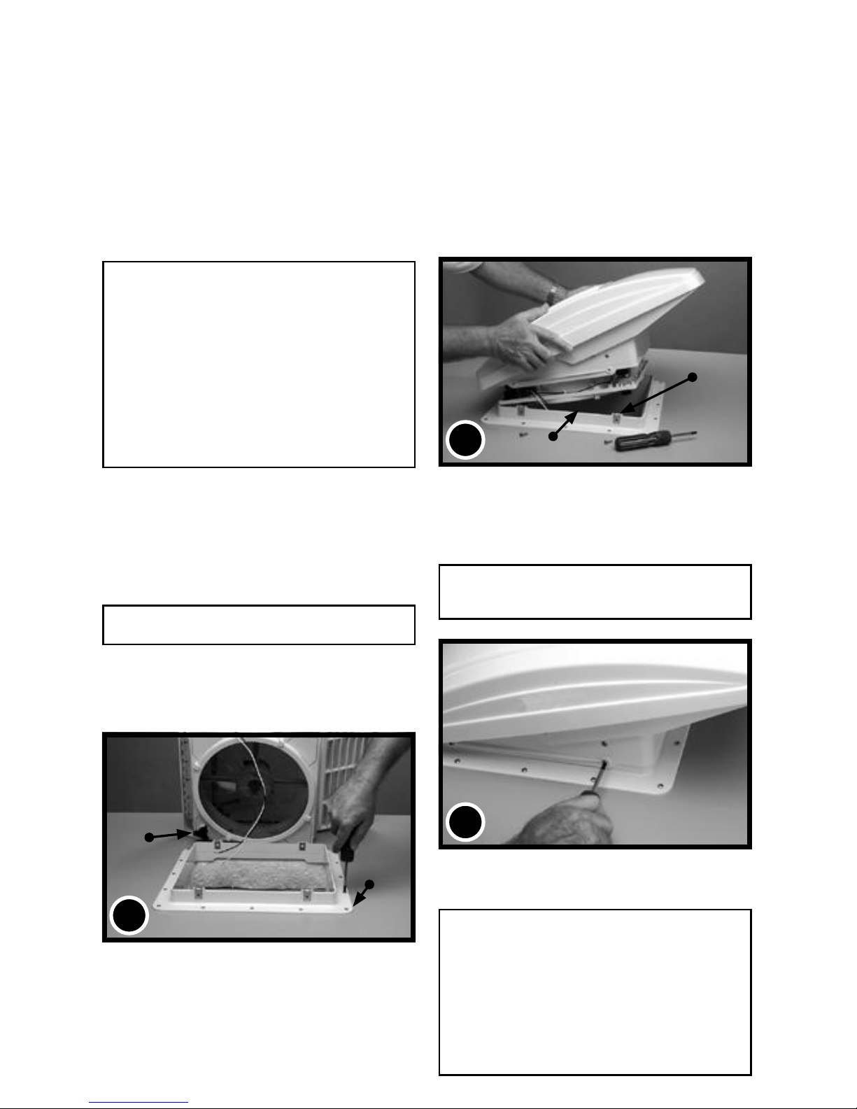
STEP 4
Conrm the 4 metal mounting clips are rmly in place on
the Roof Receiving Flange. With the MAXXFAN open
and the exhaust/intake louvers facing the rear of the
vehicle, lower the MAXXFAN onto the Roof Receiving
Flange.
Make sure the power wires slide to the vehicle interior
and do not become entangled on the Roof Receiving
Flange’s upward edge.
STEP 5
Verify the MAXXFAN is fully seated down on the Roof
Receiving Flange and fasten the MAXXFAN to the Roof
Receiving Flange using the four 3/4” #10 stainless steel
screws provided.
CAUTION: Only use the screws provided/specied
for this installation or internal damage and/or insecure
mounting may result.
STEP 1
MAXXFAN requires a roof opening of 14” x 14”. If you
are replacing another type already installed, remove the
old existing roof vent. Remove all old roof sealant for a
minimum of 2” entirely around the roof opening.
Place the MAXXFAN Roof Receiving Flange (reference
photo #2 below) into the roof opening and trace a pencil
line around it to verify the clean seal area that will be
required. Note that the Roof Receiving Flange must be
centered in the roof opening with the metal clips facing
the sides of the vehicle (not facing the front or rear of the
vehicle).
CAUTION: When installing your Roof Flange, only
use a caulking/sealant compatible with the ange
(plastic product) and the roof surface. DO NOT
use materials containing solvents such as or similar
to Xylene, Toluene, Methyl Ethyl Ketone, Acetate
or Acetone as they can damage the ange. Also,
Polysulde (Thiokol) type sealants must be avoided.
Silicone Sealants such as G.E. Silicone II (nonpaintable) used for outdoor applications have proven
to be suitable for this installation.
If in doubt, please contact the manufacturer of your
RV for further information.
STEP 2
Apply Sealant or Caulking within the area you have traced
on the roof with a pencil. Apply it carefully to avoid gaps
that may allow water to enter.
Fasten the Roof Receiving Flange to the roof with
screws provided.
Apply additional roof sealant over the screw heads and
around the edge of the roof ange.
CAUTION: Disconnect main vehicle power before
connecting 12 volt DC power to the MAXXFAN!
NOTE: The MAXXFAN must be fully opened prior to
proceeding to STEP 3. Turn knob to fully raise the vent
lid.
NOTE: On the NON-REMOTE controlled models, the
knob must be pulled out to unlock before turning.
STEP 3
Using the insulated electrical connectors provided,
connect the vehicle’s 12 volt power to the two
MAXXFAN power wires located on the driver side of
the MAXXFAN.
NOTE: The MAXXFAN black wire identied with a tag
THIS COMPLETES THE ROOF TOP
PORTION OF THE INSTALLATION
NOTE: Re-apply 12 volt vehicle power. The MAXXFAN,
excluding the 5301K and 6401K, will emit a beeping sound
to indicate power is properly connected. In addition, the
Remote Control model will automatically close the vent cover.
If the MAXXFAN does not beep when power is connected,
go back to step #3. Conrm that proper connections were
made and 12 volt power is on and available. This MAXXFAN
incorporates a self-resetting fuse on the circuit board located
in the ceiling assembly. It can be reset by removing and reapplying power. If your fan fails to operate or needs reset,
contact Customer Service at 316.832.4357 for assistance or
solicit the aid of an electrical technician.
RECEIVING FLANGE
UPPER EDGE
METAL MOUNTING
CLIPS
4
INSTALLATION INSTRUCTIONS - ALL MODELS
OPEN / CLOSE
KNOB
ROOF FLANGE
2
2
GARNISH RING
GARNISH RING
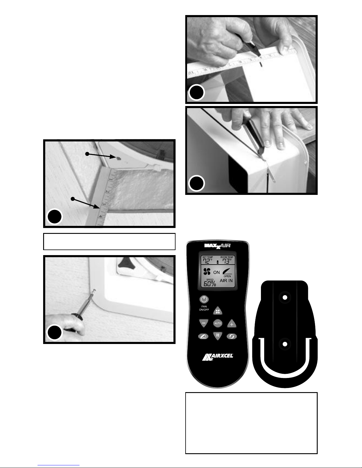
STEP 7
Complete the installation by placing any excess wiring
to the inside of the roof opening and sliding the Garnish
Ring into position. Fasten in place by using the four
painted at head screws provided.
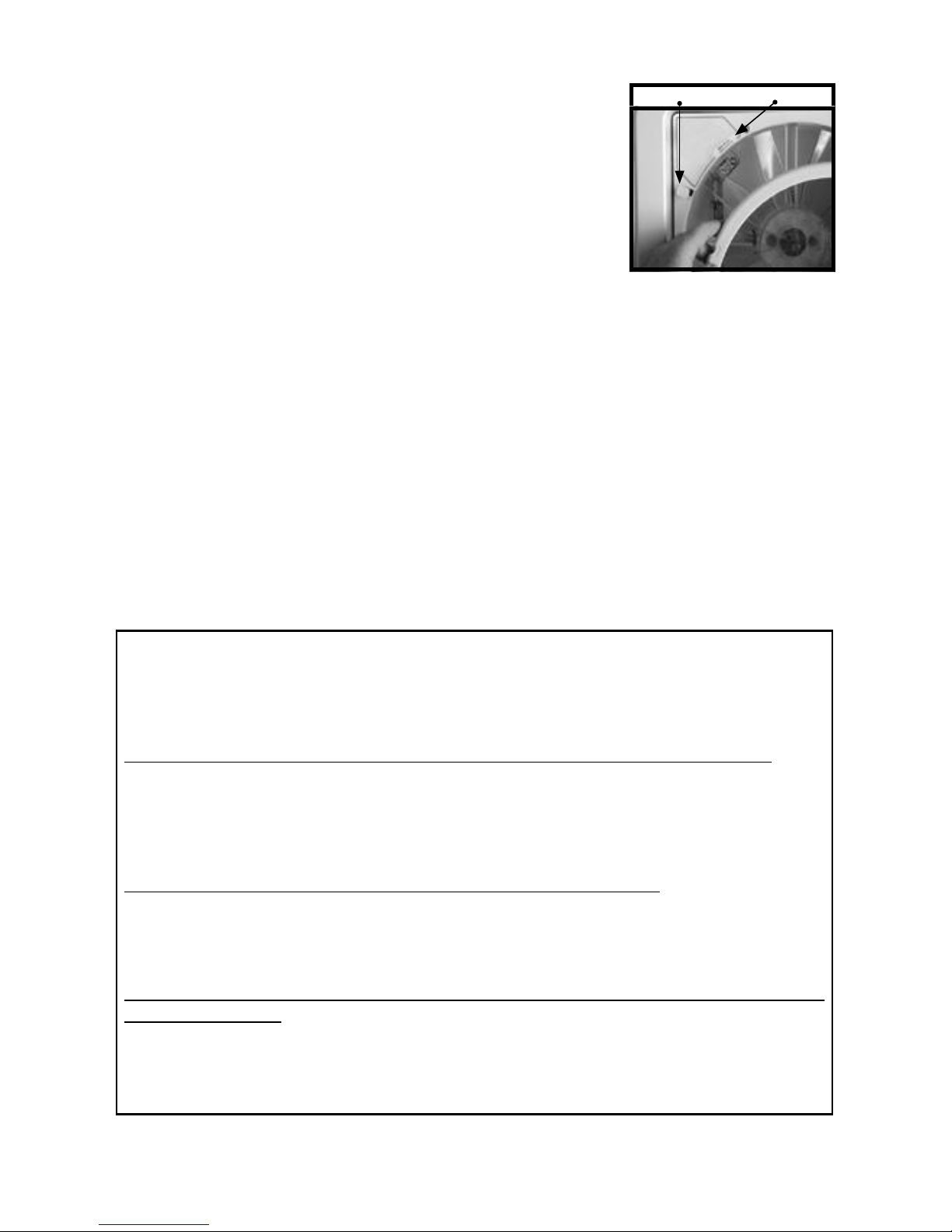
NOTE: DO NOT probe or tamper with the thermostat
sensor or IR sensor shown in illustration #6 above.
7
CONGRATULATIONS!!!
You have successfully completed the
installation of your new
MAXXFAN Deluxe.
If you have questions, please visit
AIRXCEL.com or contact
Customer Service at 316.832.4357.
6A
6B
STEP 6
The interior Garnish Trim Ring must be trimmed to t
your particular RV roof thickness. To accomplish this,
measure the distance from the vehicle ceiling surface to
each corner of the MAXXFAN Control Plate.
Most RV roofs have some slope, so measuring each
corner is necessary. The Garnish ring should be cut
1/4” to 1/2” longer than the dimensions measured at
each corner.
In Picture #6 below, the installation measures 3 1/2”
from the ceiling (this is an example only) to the Control
Plate. After adding 1/2” as in this example, using a ruler,
place a mark at 4” on each corner of each side of the
Garnish Ring (refer to 6A, right). Once marked, draw a
line connecting all 4” marks on the outside of the Garnish
ring and trim accordingly (refer to 6B, right).
FOR REMOTE CONTROL MODELS: Refer to
the Operating Instructions for use and testing of your
remote control. Install two AAA batteries, follow
instructions, aim remote at the ceiling unit and test
your fan. The Remote Control comes with a cradle
for wall mount storage of the Handheld Remote
Control. Mount the cradle to your wall using the (2)
#6 screws provided. Remote may be placed into the
wall cradle for storage.
THERMOSTAT
SENSOR
3 1/2”
CEILING
6
MEASUREMENTS STATED IN STEP
6 ARE USED AS AN EXAMPLE FOR
ILLUSTRATION PURPOSES ONLY
3
AIRXCEL, INC. - RV PRODUCTS DIVISION / MAXXAIR
Ventilation Solutions warrants to be free of manufacturing
defects, regardless of ownership for a period of two (2) years
from the original date of purchase. If the product is installed as
original equipment on a vehicle, the warranty period shall begin
on the date of the original purchase of the vehicle. In all other
instances, the warranty shall begin on the date the product
was purchased. You must keep your original sales receipt.
This Limited Warranty does not include “Acts of God,” failure
due to misuse, improper installation or accidental / incidental
damages. Please call AIRXCEL, INC. at 1-316-832-4357 if you have any questions or
need assistance.
Please have your original sales receipt and MAXXFAN Serial Number readily
available. AIRXCEL will correct the confirmed defect within 45 days by repair or
replacement without charge for materials and labor. This limited warranty does not cover
any freight costs for the return of the product to or from AIRXCEL, INC. or costs associated
with installation, removal or reinstallation of the product.
We invite your comments and suggestions regarding our products. Any information you
supply is for AIRXCEL / MAXXAIR’s internal use and will not be shared or sold to others.
The Serial Number for your MAXXFAN is located on the back page of this booklet and on the fan
control plate under the round insect screen frame. (Your serial number may or may not be located in
the same position as referenced in the above image). Reference your operating guide. Rotate the
four retaining knobs 180° and remove the screen to view. DO NOT OPERATE the MAXXFAN with
the screen removed.
CAUTIONS AND CARE OF YOUR MAXXFAN
®
This product has been manufactured using prime UV stabilized Polymers for maximum
toughness and durability. However, the use of caustic or solvent based chemicals can
cause cracking and product failure.
PLEASE CLEAN ALL PARTS WITH MILD SOAP AND WATER ONLY.
Do not use Petroleum Containing Additives or Solvent Based Products on any of the
MAXXFAN’s components or its corrosion resistant hardware.
LISTED BELOW ARE SOME KNOWN CHEMICAL PRODUCTS TO BE
AWARE OF:
NON COMPATIBLE CHEMICALS - DO NOT USE THESE:
Ketones, Esters, Acetone or other like solvents, Halogenated Hydrocarbons,
Amines, Aromatic Hydrocarbons, (Loctite Formulas), or any products containing
references to: chemicals that are not to be used on plastics.
GENERALLY COMPATIBLE (But should be used in low concentration
where possible)
Acids, Alcohol, Alkalis, Aliphatic Hydrocarbons, Mild Soap Solution (avoid strong
Alkaline Material), Silicone Oil or Greases (avoid those containing Aromatic
Hydrocarbons or other additives). Review the contents of your cleaning materials
carefully.
For additional information regarding your NEW MAXXFAN® Deluxe,
please refer to the INFORMATION AND OPERATION GUIDES
FOR YOUR PARTICULAR MODEL ON THE FOLLOWING PAGES.
MAXXFAN® 2 YEAR LIMITED WARRANTY
SERIAL NUMBERRETAINING KNOB
4
 Loading...