

Maxxair 5100KI, 6200KI, MAXXFAN Deluxe, 7500KI, 5100KI40 Instructions Manual
...
®
“More information https://www.caravansplus.com.au"
MAXXFAN
INSTALLATION INSTRUCTIONS,
INFORMATION AND OPERATING GUIDE
FOR MAXXFAN® Deluxe MODELS
5100KI • 6200KI • 7000KI • 7500KI
5100KI40 • 6200KI40 • 7000KI40 • 7500KI40
READ AND SAVE THESE INSTRUCTIONS
NOTE: Refer to supplied Operating Instructions regarding the model you have purchased.
The MAXXFAN installs into a standard RV roof opening of 355mm x 355mm for KI models
and 400mm x 400mm for KI40 models.
To determine if your roof opening is correctly sized, simply remove the interior ceiling garnish
trim ring of your existing roof vent and measure the ceiling opening or verify the opening is
large enough by sliding the MAXXFAN interior garnish trim ring into the opening.
Due to the EXHAUST / INTAKE LOUVERS that face the rear of the vehicle, the MAXXFAN
requires a roof area clear of obstructions such as air conditioners, storage boxes, etc. for at
least 203 mm to the rear of the existing standard roof vent ange outer rear edge.
The MAXXFAN is designed for a minimum roof thickness of 25mm to a maximum of
90mm. If your roof thickness is less than 25mm, build additional thickness at the ceiling
opening using wood or other suitable material. Longer Ganish Rings are available to allow
installation in caravans with thicker roof sections.
The MAXXFAN is designed for a nominal 12 Volt DC system and requires a circuit capable
of supplying a minimum of 5 amps to the MAXXFAN. Conrm that the circuit you intend
to use will accommodate the additional load. Use the proper gauge stranded wire for
electrical connections.
WARNING! To reduce risk of re, injury to persons or damage to property, use only
in the manner intended by AIRXCEL, INC. Should you have questions, please contact
your AIRXCEL/MAXXAIR Distributor.
P/N: 11-90001KI
REV NEW, 05-08-2015
INSTALLATION INSTRUCTIONS - ALL MODELS
“More information https://www.caravansplus.com.au"
STEP 1
MAXXFAN requires a roof opening opeining of 355mm
x 355mm for KI models and a roof opening of 400mm x
400mm for KI40 models. If you are replacing another
type already installed, remove the old existing roof vent.
Remove all old roof sealant for a minimum of 50mm
entirely around the roof opening.
Place the MAXXFAN Roof Receiving Flange (reference
photo #2 below) into the roof opening and trace a pencil
line around it to verify the clean seal area that will be
required. Note that the Roof Receiving Flange must be
centered in the roof opening with the metal clips facing
the sides of the vehicle (not facing the front or rear of the
vehicle).
CAUTION: When installing your Roof Flange, only
use a caulking/sealant compatible with the ange
(plastic product) and the roof surface. DO NOT
use materials containing solvents such as or similar
to Xylene, Toluene, Methyl Ethyl Ketone, Acetate
or Acetone as they can damage the ange. Also,
Polysulde (Thiokol) type sealants must be avoided.
Silicone Sealants such as G.E. Silicone II (nonpaintable) used for outdoor applications have proven
to be suitable for this installation.
If in doubt, please contact the manufacturer of your
RV for further information.
STEP 2
Apply Sealant or Caulking within the area you have traced
on the roof with a pencil. Apply it carefully to avoid gaps
that may allow water to enter.
Fasten the Roof Receiving Flange to the roof with
screws provided.
Apply additional roof sealant over the screw heads and
around the edge of the roof ange.
CAUTION: Disconnect main vehicle power before
connecting 12 volt DC power to the MAXXFAN!
NOTE: The MAXXFAN must be fully opened prior to
proceeding to STEP 3. Turn knob to fully raise the vent
lid.
NOTE: On the NON-REMOTE controlled models, the
knob must be pulled out to unlock before turning.
CAUTION: Connecting the MAXXFAN to a circuit
other than 12 Volts DC or with incorrect polarity could
damage the MAXXFAN, cause injury to persons or
damage to property and void the warranty.
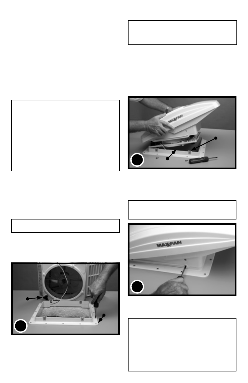
STEP 4
Conrm the 4 metal mounting clips are rmly in place on
the Roof Receiving Flange. With the MAXXFAN open
and the exhaust/intake louvers facing the rear of the
vehicle, lower the MAXXFAN onto the Roof Receiving
Flange.
Make sure the power wires slide to the vehicle interior
and do not become entangled on the Roof Receiving
Flange’s upward edge.
4
RECEIVING FLANGE
UPPER EDGE
STEP 5
Verify the MAXXFAN is fully seated down on the Roof
Receiving Flange and fasten the MAXXFAN to the Roof
Receiving Flange using the four 19mm #10 stainless
steel screws provided.
CAUTION: Only use the screws provided/specied
for this installation or internal damage and/or insecure
mounting may result.
METAL MOUNTING
CLIPS
OPEN / CLOSE
KNOB
2
STEP 3
Using the insulated electrical connectors provided,
connect the vehicle’s 12 volt power to the two MAXXFAN
power wires.
NOTE: The MAXXFAN black wire identied with a tag showing
(+) must be connected to the vehicle 12 volt (+) positive supply.
ROOF FLANGE
5
THIS COMPLETES THE ROOF TOP
PORTION OF THE INSTALLATION
NOTE: Re-apply 12 volt vehicle power. The MAXXFAN will
emit a beeping sound to indicate power is properly connected.
In addition, the Remote Control model will automatically
close the vent cover. If the MAXXFAN does not beep when
power is connected, go back to step #3. Conrm that proper
connections were made and 12 volt power is on and available.
This MAXXFAN incorporates a self-resetting fuse on the circuit
board located in the ceiling assembly. It can be reset by
removing and re-applying power. If your fan fails to operate or
needs reset, contact your AIRXCEL / MAXXAIR Distributor for
assistance or solicit the aid of an electrical technician.
2
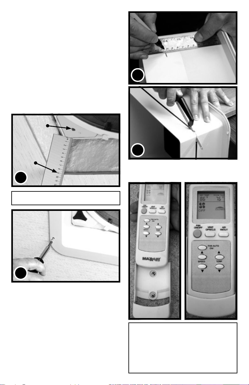
STEP 6
“More information https://www.caravansplus.com.au"
The interior Garnish Trim Ring must be trimmed to t
your particular RV roof thickness. To accomplish this,
measure the distance from the vehicle ceiling surface to
each corner of the MAXXFAN Control Plate.
Most RV roofs have some slope, so measuring each
corner is necessary. The Garnish ring should be cut
6mm to 12.5mm longer than the dimensions measured
at each corner.
In Picture #6 below, the installation measures 90mm
from the ceiling (this is an example only) to the Control
Plate. After adding 12mm as in this example, using a
ruler, place a mark at 102mm on each corner of each
side of the Garnish Ring (refer to 6A, right). Once
marked, draw a line connecting all 102 mm marks on the
outside of the Garnish ring and trim accordingly (refer
to 6B, right).
THERMOSTAT
SENSOR
6A
GARNISH RING
90mm
6
NOTE: DO NOT probe or tamper with the thermostat
sensor or IR sensor shown in illustration #6 above.
CEILING
7
STEP 7
Complete the installation by placing any excess wiring
to the inside of the roof opening and sliding the Garnish
Ring into position. Fasten in place by using the four
painted at head screws provided.
CONGRATULATIONS!!!
You have successfully completed the
installation of your new MAXXFAN.
If you have questions, please visit
AIRXCEL.com or contract your
AIRXCEL / MAXXAIR Distributor.
6B
GARNISH RING
MEASUREMENTS STATED IN STEP
6 ARE USED AS AN EXAMPLE FOR
ILLUSTRATION PURPOSES ONLY
FOR REMOTE CONTROL MODELS: Refer
to the Operating Instructions for use and testing of
your remote control. Install the two AAA batteries
included, follow instructions, aim remote at the ceiling
unit and test your fan. The Remote Control comes
with a cradle for wall mount storage of the Handheld
Remote Control. Mount the cradle to your wall using
the (2) #6 screws provided. Remote may be placed
into the wall cradle for storage.
3
 Loading...