

Page 1

DIGITAL CLAMP METER
DIGITÁLIS LAKATFOGÓ
CLEŞTE DE MĂSURAT DIGITAL
DIGITALNY KLIEŠŤOVÝ MULTIMETER
Product code / Termékkód / Cod produs / Kód produkta:
25601
User ManUal
Használati Utasítás
ManUal de Utilizare
Užívateľská prírUčka
Page 2
EN
User Manual
safety inforMation
This device is a portable digital clamp meter
with a 3 ½ digit LCD display and insulation test
function (with a 500 V insulation test unit - not
included). Please follow the prescriptions for
safety and usage to ensure proper functioning
and state of the device.
Keep all safety standards when using the
device:
• Protect yourself from the dangers of electricity
• Protect the device from improper usage.
• The compliance to the safety standards is only
guaranteed, when the measuring wires are
intact. If they are damaged, replace them to
ones of the same type immediately.
Warning
• Never exceed the given overload values in any
threshold while measuring
• When connecting the device to the measured
circuit, do not touch the unused connectors.
• If you do not know the threshold of the
measured value, set the function switch to the
highest available one.
• Disconnect the device from the circuit before
switching functions.
• Be careful when measuring TVs and switching
circuits, the high amplitude voltage impulses
on the testing points can damage the device.
• Do not measure resistance in a circuit that is
under power.
• Be careful when measuring higher values than
60 V DC or 30 V AC. Keep your ngers on the
designated area and do not touch the metal
parts.
• Stop using the device if you encounter any
errors or faulty behaviour by the device, have it
repaired by a professional.
• Never use the device if the battery holder lid
is not in its proper place, or is insuciently
fastened.
• Do not clean the device with rough materials
or solvents. Use a wet cloth and soft detergents
only.
fUnctions
• AC current measuring - Insulation test
(optional)
• DC and AC voltage measurement
• Resistance measurement
• Continuity test
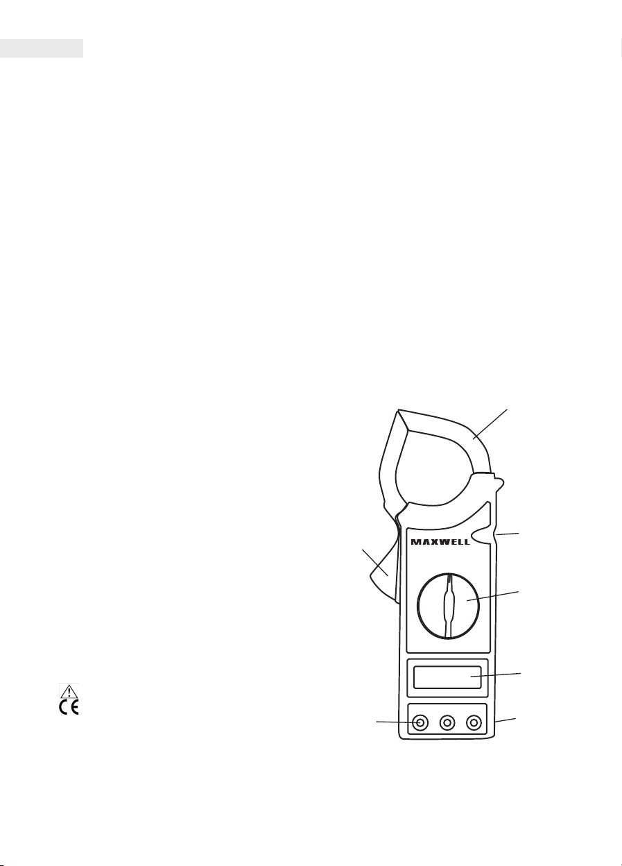
controls
1
3
2
4
Warning symbols:
• Danger/Important information
• Compliance symbol (EU standards)
• "COM" Ground (GND)
Maintenance
• Always disconnect the device from the
measured circuit before opening the cover of
the device.
5
6 7
1. Clamps
2. Trigger button
3. 'HOLD' button
Page 3
User Manual
EN
By pressing this button the device
holds the measured value on the
screen until you press the button again.
(Works with every function)
4. Function and threshold switch
This swtich enables you to select the proper
function and threshold. You can turn the device
o by setting it to the OFF position.
5. LCD display
6. Inward connectors
The device has 3 inward connectors. These have
overload protection to the limits specied in the
manual. When measuring, connect the black
wire to the 'COM' connector and the red one to
the 'VΩ' connector.
7. Wrist band
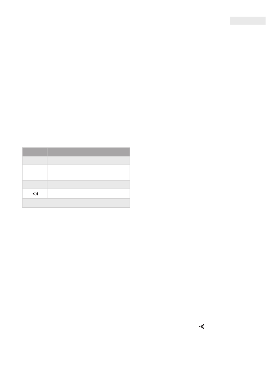
Function Inward threshold
200 mV 250 V DC or AC RMS
DC V and
AC V
1000 V DC, 750 V AC (sine)
Ω 250 V DC or AC RMS
250 V DC or AC RMS
Red wire connection: VΩ
The 'EXT' connector is for connecting an insulation tester
(with external measuring tips) when measuring insulation
resistance.
Usage
Current measuring
• Set the function switch to the appropriate AC A
threshold. Place the clamps onto the cable with
the AC current.
• If there is only a '1' on the screen, it signals
an overload, you need to switch to a higher
threshold.
Insulation testing
• Connect the wires of the insulation tester ('VΩ',
'COM', 'EXT')to the 'VΩ', 'COM', 'EXT' connectors
of the clamp meter.
• Set the function switch to the 2000 MΩ
position.
• Set the threshold to the 2000 MΩ position
• Connect the measuring arms to the 'L' and 'E'
connectors. The tester has to be turned o
when connecting.
• Turn the 'POWER' switch of the insulation meter
on.
• Press the PUSH 500V button, and the red 500V
lamp will light up. The value of the measured
insulation resistance is displayed on the screen.
If the measured value is below 19 MΩ, set the
clamp meter to 20 MΩ.
• If you do not use the insulation meter, turn it
o and remove the wires from the 'E' and 'L'
connectors. This saves battery life and reduces
the risk of electric shock.
(With connecting a 500 V insulation tester - not included)
Voltage measuring
• Connect the red wire to the 'VΩ' connector and
the black one to the 'COM' connector.
• Set the function switch to the proper AC V or
DC V setting.
• Connect to the measured circuit. The measured
value is displayed on the screen. (In case of DC
voltage measuring the polarity of the red wire
is displayed as well).
• If there is only a '1' on the screen, it signals
an overload, you need to select a higher
threshold.
Resistance measuring
• Connect the red wire to the 'VΩ' connector and
the black one 'COM' connector. (The polarity of
the red wire '+').
• Set the function switch to the proper resistance
function.
• Touch the measuring wires to the resistor and
read the value on the screen.
• If the resistance is higher than the maximum
value of the selected threshold, '1' appears on
the screen.
• If the resistor is part of a circuit, turn o the
power and discharge every high capacity
capacitors before connecting the device.
Continuity test
• Connect the red wire to the 'VΩ' connector and
the black one to the 'COM' connector.
• Set the function switch to „ ” position.
• Connect the wires to the measured circuit. If
the circuit is not broken (R< 50Ω), the device
will beep.
Page 4
EN
User Manual
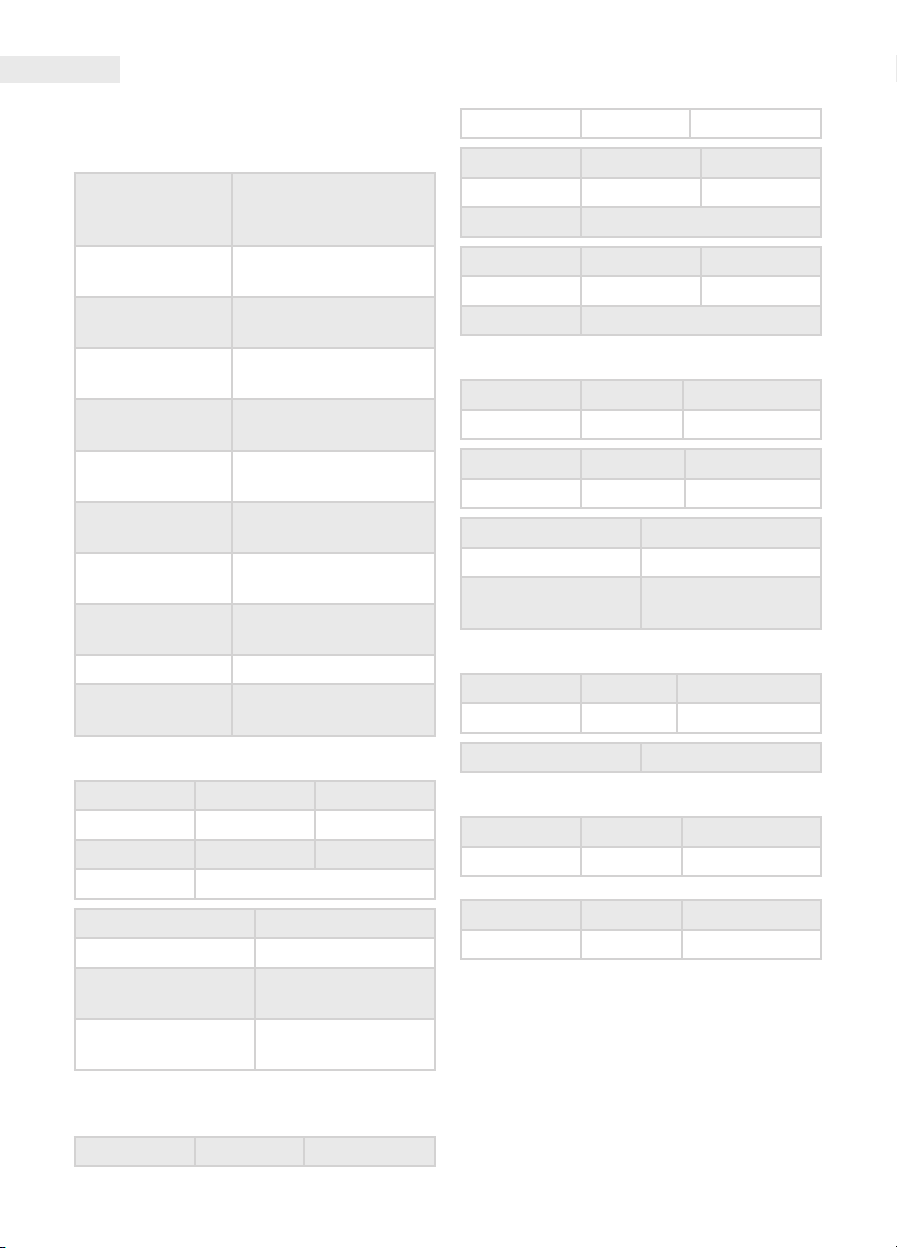
Description
• Accuracy measured at 23 °C+/-5 °C, with <80%
relative humidity.
Max. voltage btw
the connectors
and GND
Battery
Display
Measuring
method
Overload display
Polarity display
Operating
temperature
Storage
temperature
Low battery signal
Dimensions 230mm x 90mm x 37mm
Weight
1000V DC or 750 V AC
RMS (sine)
9 V 6F22 or NEDA 1604
type
max. value: 1999
Update: 2-3/second
Dual-slope A/D
converter
Only a „1” is displayed on
the screen.
'-' signals negative
polarity
0 °C-40 °C (32 °F-104 °F)
-10 °C-50 °C
(10 °F-122 °F)
'BAT' appears on the
screen
appr. 320 g (with
battery)
20 MΩ 10 kΩ +/- 2.0% +/- 2d
Threshold Resolution Note
2000 MΩ 1 MΩ < 500 MΩ
Pontosság +/- 4.0% +/- 2d
Threshold Resolution Note
2000 MΩ 1 MΩ < 500 MΩ
Pontosság +/- 5.0% +/- 2d
AC voltage
Threshold Resolution Accuracy
200 V 100 mV +/- 1,0% +/-4d
Threshold Resolution Accuracy
750 V > 9 MΩ 1 V +/- 1,0% +/-4d
Inward impedance 9 MΩ
Frequency range 50 Hz–500 Hz
Displayed value
DC voltage
Threshold Resolution Accuracy
1000 V 1V +/- 0,8% +/-2d
average, veried with
a sine (RMS)
AC current
Threshold Resolution Note
200 A 100 mA
1000 A 1A < 800 A
Accuracy +/-2.0% +/- 5d
Frequency range 50 Hz– 60 Hz
Overload protection 1200 A, 60 seconds
Displayed value
Distance between
clamps
Insulation testing
With an external 500V insulation tester (not
included)
Threshold Resolution Accuracy
average, veried with
a sine (RMS)
5 cm
Inward impedance 9 MΩ
Resistance
Threshold Resolution Accuracy
200 Ω 0,1 Ω +/- 1,0% +/- 3d
Threshold Resolution Accuracy
20k Ω 10 Ω +/- 1,0% +/- 1d
accessories
• Battery (9V, 6F22 or NEDA 1604 type)
• Measuring wires (1 pair)
• User manual
Page 5

Battery replaceMent
If the "BAT" sign appears on the screen, the
battery in the device needs to be replaced.
• Turn the device o and remove the measuring
wires.
• Remove the screw holding the battery
container lid, and remove the lid.
• Remove the depleted battery and replace it to
a new one of the same type
• Replace the lid and screw it back in.
Warning: Always make sure that the wires are disconnected
from any measured circuits before opening the container
lid. Close and screw back the lid before using the device
again.
User Manual
EN
Page 6
HU
Használati utasítás
Biztonsági tájékoztatás
Ez a műszer hordozható, 3 ½ digites LCD
kijelzős digitális lakatfogó, szigetelésvizsgáló
funkcióval (500 V-os szigetelésvizsgálóegységgel
(nemtartozék!))-opció. Kövesse a biztonsági
és használati utasításokat, így biztosíthatja a
műszer biztonságos működését és jó állapotát.
Használat közben tartsa be az összes
biztonsági szabványt:
• Védekezés az elektromos áram veszélyei ellen.
• Óvja a műszert a szakszerűtlen használattól.
• A biztonsági szabványoknak való megfelelés
csak a műszerzsinórok hibátlan állapotában
garantált. Sérülésük esetén azonnal cserélje ki
azokat ugyanolyan típusúra.
figyelMeztetés
• Egyetlen méréshatárban se lépje túl a használati
utasításban megadott túlterhelési értéket.
• Amikor a műszerrel a mérendő áramkörhöz
csatlakozik, ne érintse a használaton kívüli
aljzatokat.
• Ha a mérendő mennyiség értéktartományát
nem ismeri a mérés előtt, állítsa a
funkcióválasztó kapcsolót a legmagasabb
méréshatárra.
• Funkcióváltás előtt szakítsa meg a kapcsolatot
a mérendő áramkörrel.
• TV és kapcsolóüzemű áramkörök mérésekor
legyen óvatos, a tesztpontokon fellépő nagy
amplitúdójú feszültségimpulzusok a műszert
tönkretehetik.
• Ne mérjen ellenállást feszültség alatt lévő
áramkörben.
• Legyen körültekintő 60 V DC vagy 30 V AC
(RMS)-nál magasabb feszültség mérésénél.
Tartsa ujjait a tapogató korlátja mögött. Ne
érintse a tapogató fém érintkezőjét.
karBantartás
• A műszer burkolatának kinyitása előtt mindig
szüntesse meg a kapcsolatot a feszültség alatt
lévő áramkörökkel.
• Ha bármilyen hibát vagy rendellenességet
észlel, a műszert ne használja tovább, feltétlenül
javíttassa meg szakemberrel.
• Soha ne használja a műszert, ha az elemtartó
fedele nincs a helyén vagy nincs tökéletesen
rögzítve.
• Ne tisztítsa a műszert érdes eszközzökkel vagy
oldószeres anyagokkal. Használjon nedves
ruhát és enyhe tisztítószert.
fUnkciók
• AC áram mérés -Szigetelés vizsgálat (opció)
• DC és AC feszültségmérés
• Ellenállásmérés
• Folytonosság teszt
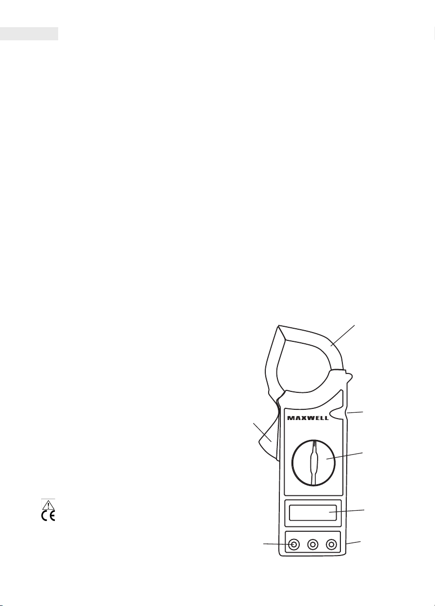
kezelőszervek
1
3
2
4
Figyelmeztető szimbólumok:
• Veszély/fontos információ
• Megfelelősségi szimbólum
(EU szabványnak)
• "COM" Föld (GND)
5
6 7
Page 7
Használati utasítás
HU
1. Lakatfogó kapcsok
2. Kioldógomb
3. 'HOLD'nyomógomb
A gomb megnyomásának hatására a kijelzőn
az éppen akkor mért érték marad, addig,
amíg újra meg nem nyomja a gombot.
(Minden funkciónál működik.)
4. Funkció és méréshatár kapcsoló
Ezzel a kapcsolóval választhatja ki a kívánt
funkciót és méréshatárt. A kapcsolót OFF
állásába állítva a műszert kikapcsolhatja.
5. LCDkijelző
6. Bemeneti csatlakozók
A műszeren 3 bemeneti csatlakozó található.
Ezek rendelkeznek túlterhelés elleni védelemmel
a táblázatban megadott határokig. Mérésnél
csatlakoztassa a fekete mérőzsinórt a 'COM'
aljzatba, a pirosat pedig a 'VΩ' jelzésű
csatlakozóba.
7. Tartószíj
Funkció Bemeneti határértékek
200 mV 250 V DC vagy AC RMS
DC V és
AC V
1000 V DC, 750 V AC (szinuszos)
Ω 250 V DC vagy AC RMS
250 V DC vagy AC RMS
Piros műszerzsinór csatlakozása: VΩ
Az 'EXT' aljzat szigetelésvizsgáló csatlakoztatására szolgál
(külső banándugókkal), szigetelési ellenállás mérésénél.
• Állítsa a szigetelésvizsgáló méréshatár
kapcsolóját a 2000 MΩ pozícióba
• Csatlakoztassa a tapogatókat a
szigetelésvizsgáló 'L' és 'E' bemeneteire. Ezalatt
a teszternek kikapcsolt állapotban kell lennie.
• Állítsa a szigetelésvizsgáló 'POWER' kapcsolóját
'ON' állásba.
• Nyomja meg a PUSH 500V nyomógombot,
ekkor az 500V jelzésű piros lámpa világít. A
lakatfogó kijelzőjén a szigetelési ellenállás
értéke látható. Ha a mért érték 19 MΩ-nál
kisebb, álllítsa a lakatfogót a 20 MΩ-o
• Ha a szigetelésvizsgálót nem használja,
kapcsolja ki és a mérőzsinórokat az 'E' és 'L'
jelű aljzatokból húzza ki. Ezzel megnövelheti
az elemek élettartamát és csökkentheti az
áramütés veszélyét.
(500 V-os szigetelésvizsgáló egység csatlakoztatásával - nem
tartozék)
Feszültség mérése
• Csatlakoztassa a piros csatlakozót a 'VΩ' , a
feketét pedig a 'COM' aljzatba.
• Állítsa a funkciókapcsolót a megfelelő
AC V vagy DC V állásba.
• Érintse a tapogatókat a mérendő
feszültségforráshoz, és a feszültség értékét
a kijelzőről leolvashatja. (DC feszültség
mérésénél a piros tapogató polaritását jelzi a
műszer)
• Ha a kijelzőn csak az '1' felirat látható, az
túlterhelést jelez, állítsa a funkciókapcsolót
magasabb méréshatárra.
Használat
Áram mérése
• Állítsa a funkciókapcsolót a megfelelő AC A
méréshatárra. A lakatfogó kapcsokat csíptesse
a váltóárammal átjárt vezetőre.
• Ha csak az '1' jelzés látható a kijelzőn, az a
túlterhelést jelzi, ilyenkor kapcsoljon magasabb
méréshatárra.
Szigetelés vizsgálat
• Csatlakoztassa a szigetelésvizsgáló 'VΩ', 'COM',
'EXT' banándugóit a lakatfogó 'VΩ', 'COM', 'EXT'
aljzataiba.
• Állítsa a lakatfogó funkciókapcsolóját a 2000
MΩ állásba.
Ellenállásmérés
• Csatlakoztassa a piros csatlakozót a 'VΩ',
a feketét pedig a 'COM' aljzatba. (A piros
műszerzsinór polaritása: '+'.)
• Állítsa a funkciókapcsolót a megfelelő ellenállás
pozícióba.
• Érintse a tapogatókat az ellenálláshoz, és a
kijelzőről leolvashatja a mért értéket.
• Ha az ellenállás értéke nagyobb a választott
méréshatár maximális értékénél vagy a
kimenetre nem csatlakoztat ellenállást, a
kijelzőn az '1' felirat látható.
• Ha az ellenállás áramkör részét képezi,
kapcsolja ki a tápfeszültséget és süssön ki
minden kondenzátort, mielőtt csatlakoztatnáa
műszerhez.
Page 8
HU
Használati utasítás
Folytonosság teszt
• Csatlakoztassa a piros csatlakozót a 'VΩ', a
feketét pedig a 'COM' aljzatba.
• Állítsa a funkciókapcsolót a „ ” állásba.
• Csatlakoztassa a tapogatókat a tesztelendő
áramkör két pontjához. Ha az áramkör nem
szakadt (R< 50Ω), a beépített síp hangjelzést
ad.
Leírás
• A pontosság, 23 °C+/-5 °C-on, 80%-nál kisebb
relatív páratartalom esetén.
Maximális
feszültség az
aljzatok és a GND
1000V DC vagy 750 V AC
RMS (szinuszos)
között
Elem
Kijelző
Mérési eljárás
Túlterhelés kijelzés
Polaritás kijelzés
Üzemi
hőmérséklet
Tárolási
hőmérséklet
Alacsony
telepfeszültség
kijelzése
9 V 6F22 vagy NEDA
1604 típusú
max. érték: 1999
Frissítés: 2-3/másodperc
Dual-slope A/D
konverter
Csak az „1” jelenik meg a
kijelzőn
A '-' jelzi a negatív
polaritást
0 °C-40 °C (32 °F-104 °F)
-10 °C-50 °C
(10 °F-122 °F)
Az'BAT' felirat
megjelenik a kijelzőn
Méretek 230mm x 90mm x 37mm
Tömeg kb. 320 g (elemmel)
AC áram
Méréshatár Felbontás Megjegyzés
200 A 100 mA
1000 A 1A < 800 A
Pontosság +/-2.0% +/- 5d
Frekvencia tartomány 50 Hz– 60 Hz
Túlterhelés elleni
védelem
Jelzett érték
1200 A, 60
másodpercig
átlag, szinuszjellel
(RMS) hitelesítve
Kapcsok nyílása 5 cm
Szigetelésvizsgálat
Külső 500 V-os szigetelés vizsgálóval
( nem tartozék)
Méréshatár Felbontás Pontosság
20 MΩ 10 kΩ +/- 2.0% +/- 2d
Méréshatár Felbontás Megjegyzés
2000 MΩ 1 MΩ < 500 MΩ
Pontosság +/- 4.0% +/- 2d
Méréshatár Felbontás Megjegyzés
2000 MΩ 1 MΩ < 500 MΩ
Pontosság +/- 5.0% +/- 2d
AC feszültség
Méréshatár Felbontás Pontosság
200 V 100 mV +/- 1,0% +/-4d
Méréshatár Felbontás Pontosság
750 V > 9 MΩ 1 V +/- 1,0% +/-4d
Bemeneti impedancia 9 MΩ
Frekvencia tartomány 50 Hz–500 Hz
Jelzett érték
átlag, szinuszjellel
(RMS) hitelesítve
Page 9
DC feszültség
Méréshatár Felbontás Pontosság
1000 V 1V +/- 0,8% +/-2d
Bemeneti impedancia 9 MΩ
Ellenállás
Méréshatár Felbontás Pontosság
200 Ω 0,1 Ω +/- 1,0% +/- 3d
Méréshatár Felbontás Pontosság
20k Ω 10 Ω +/- 1,0% +/- 1d
tartozékok
• Elem (9V, 6F22 vagy NEDA 1604 típusú)
• Műszerzsinór (1pár)
• Használati utasítás
eleMcsere
Az 'BAT' felirat megjelenése a kijelzőn, jelzi
az elemcsere esedékességét. Lazítsa ki a
csavarokat a műszer hátlapján és nyissa ki a
burkolatot. Cserélje ki a lemerült elemet egy
ugyanolyan típusú új elemre. Ügyeljen az elem
helyes polaritással történő csatlakoztatására.
Figyelmeztetés: Mielőtt a műszer burkolatát
eltávolítaná, mindig győződjön meg, hogy a
műszerzsinórokat lecsatlakoztatta a mérendő
áramkörről. Zárja vissza a tokot és húzza meg
a csavarokat mielőtt a műszert újrahasználná
áramütés veszélye miatt.
Használati utasítás
HU
Page 10

RO
Manual de utilizare
inforMare de secUritate
Acest instrument este un cleşte de măsurat digital,
portabil, cu aşaj LCD de 3 cifre şi 1/2 cu funcţie
de testare izolaţie (cu unitate de testare izolaţii
de 500V - (nu este între accesorii)) E opţiune.
Urmaţi instrucţiunile de siguranţă şi de utilizare,
astfel puteţi asigura funcţionarea în condiţii de
siguranţă şi starea bună a instrumentului.
În timpul utilizării respectaţi toate
standardele de siguranţă:
• Autoapărarea împotriva pericolelor de energie
electrică.
• Protejaţi instrumentul de la utilizarea
neprofesională.
• Conformitatea la standardele de siguranţă
este garantată doar cu starea impecabilă al
cablurilor de testare. În cazul vătămării acestora
imediat să înlocuiţi acestea cu altele noi de
acelaşi tip.
avertisMent
• În nici un domeniu de măsurare să nu depăşiţi
valoarea de suprasarcină date în instrucţiunile
de utilizare.
• Când conectaţi instrumentul la circuitul care
urmează să e măsurat nu atingeţi prizele
neutilizate.
• În cazul în care nu ştiţi domeniul valorii care
urmează să e măsurat înainte de măsurare,
poziţionaţi comutatorul de funcţii la cel mai
mare domeniu de măsurare.
• Înainte de a schimbarea domeniului de
măsurat deconectaţi instrumentul de circuitul
care urmează să e măsurat.
• La măsurarea TV şi circuitelor în comutaţie
ţi foarte precaut; impulsurile de mare
amplitudine care apar în punctele de testare
pot distruge instrumentul.
• Nu măsuraţi rezistor în circuit sub tensiune.
• Fiţi precaut la măsurare de tensiuni mai mari de
60 VCC sau 30 VAC (RMS). Păstraţi-vă degetele
în spatele opritorului de deget de pe tentacul.
Nu atingeţi părţile metalice al tentaculelor.
Simboluri de avertizare:
• Pericol/informaţie importantă
• Simbol de conformitate (la directive EU)
• "COM" Sol (GND)
Întreţinere
• Înainte de deschiderea învelişului instrumentul
deconectaţi întotdeauna din orice circuit sub
tensiune.
• În cazul în care orice eroare sau anomalie
detectaţi, nu folosiţi instrumentul mai departe.
Duceţi imediat la depanator specialist.
• Nu folosiţi niciodată instrumentul în cazul în
care capacul bateriei nu este la locul lui sau nu
este xat pe deplin.
• Nu curăţaţi instrumentul decât cu detergent
slab.
fUncţii
• Măsurare de curent AC - testare izolaţie
(opţiune)
• Măsurare de tensiune DC şi AC
• Măsurare rezistenţă
• Test continuitate
Page 11
Manual de utilizare
RO
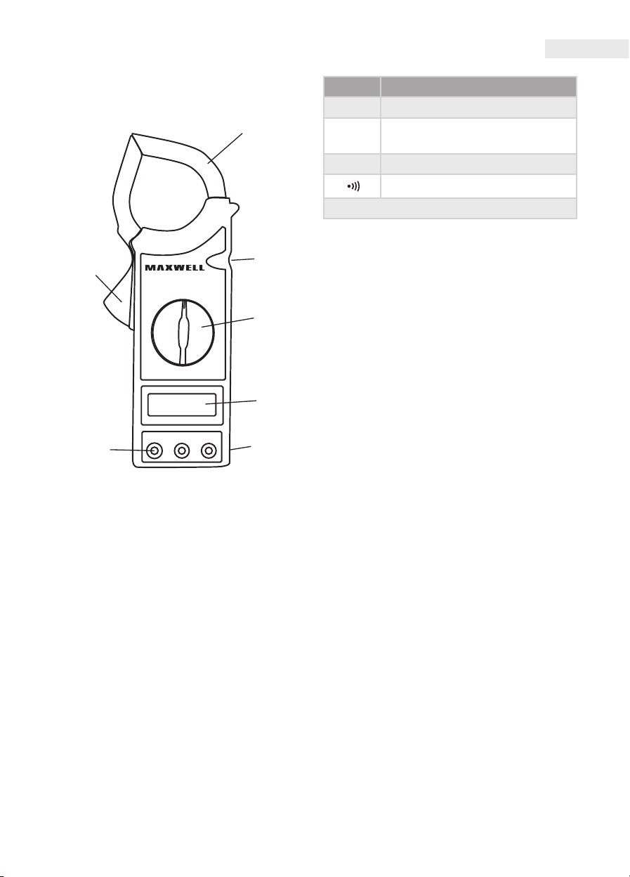
organe de Manevră
1
3
2
4
5
6 7
1. Fălcile cleştelui de măsură
2. Buton declanşator
3. Butonul 'HOLD'
La apăsarea acestui buton valoarea măsurată
rămâne aşat pe aşaj până când nu apăsaţi
butonul din nou. (Funcţionează în orice funcţie.)
4. Comutator de funcţii şi domenii de măsurat
Cu acest comutator puteţi selecta funcţia dorită
şi domeniul de măsurat. Puteţi opri instrumentul
trecând comutatorul la poziţia OFF.
5. Aşaj LCD
6. Banane de intrare
Pe instrument se găsesc 3 banane de intrare.
Acestea dispun de protecţie împotriva
suprasarcinii până la limitele date în tabel. La
măsurat conectaţi cablul de testare negru la
banana "COM", respectiv cel roşu la banana "VU".
7. Curea de mână
Funcţia Valori limită de intrare
200 mV 250 V DC sau AC RMS
DC V sau
AC V
Cablul de testare Roşie se conectează la: VΩ
Banana "EXT" serveşte pentru conectarea testerului de
izolaţie (cu banane externe), la măsurarea de rezistenţă al
izolaţiei.
1000 V DC, 750 V AC (sinusoidal)
Ω 250 V DC sau AC RMS
250 V DC sau AC RMS
Utilizare
Măsurarea curentului
• Setaţi comutatorul de funcţii la domeniul
corespunzător de AC A. Fălcile de cleşte al
instrumentului aşezaţi în jurul conductorului
străbătut de curentul alternativ.
• În cazul în care doar semnul '1 'este aşat, care
indică suprasarcina treceţi la un domeniu mai
mare.
Testare de izolaţie
• Conectaţi bananele 'VΩ', 'COM', 'EXT' ale
testerului de izolaţie la bananele 'VΩ', 'COM',
'EXT' ale cleştelui de măsurat.
• Comutaţi selectorul de funcţii la poziţia 2000
MΩ.
• Comutaţi selectorul de domeniu al testerului
de izolaţie la poziţia 2000 MΩ.
• Conectaţi tentaculele testerului de irolaţie la
intrările 'L' şi 'E'. În acest timp testerul trebuie să
e oprit.
• Aşezaţi comutatorul 'POWER' al testerului de
izolaţie în poziţia 'ON'.
• Apăsaţi butonul PUSH 500V, în acest caz
beculeţul roşu marcat cu 500V se aprinde.
Pe aşajul cleştelui de măsurat se va vedea
valoarea rezistenţei izolatorului testat.
• Dacă valoarea măsurată este mai mică de 19
MΩ, comutaţi domeniul de măsurat pe cleştele
de măsurat la20 MΩ.
• Dacă nu folosiţi testerul de izolaţie, opriţi-l şi
scoateţi tentaculele din bananele marcate cu 'E'
şi 'L'. Cu aceasta creşte durata de viaţă a bateriei
şi reduceţi riscul de electrocutare.
(cu conectarea unităţii de testare izolaţie cu 500 V – nu este în
dotare)
Page 12
RO
Manual de utilizare
Măsurarea tensiunii
• Conectaţi cablul de testare roşie la banana 'VΩ'
, iar cel negru la 'COM'.
• Setaţi comutatorul de funcţii la poziţia AC V
sauDC V potrivită.
• Atingeţi vârful cablurilor de testare la sursa de
tensiune ce va măsurat şi valoarea tensiunii
veţi putea citi de pe aşaj. (în cazul când
măsuraţi tensiune continuă instrumentul va
aşa polaritarea cablului de testare roşie)
• Dacă pe aşaj doar '1' se vede, aşajul indică
revărsare, setaţi comutatorul de funcţii la un
domeniu mai mare de măsurare.
Măsurare de rezistenţă
• Conectaţi cablul de testare roşie la banana 'VΩ'
, iar cel negru la 'COM'. (Polaritatea cablului de
testare roşie este: '+'.)
• Setaţi comutatorul de funcţii în domeniul de
rezistenţă corespunzătoare.
• Atingeţi vârful cablurilor de testare la rezistor şi
pe aşaj citiţi valoarea măsurată.
• Dacă valoarea rezistorului este mai mare decât
valoarea maximă al domeniului de măsurat
ales sau pe terminale nu aţi conectat rezistor,
pe aşaj se vede '1'.
• Dacă rezistorul este parte al unui circuit
deconectaţi circuitul şi descărcaţi
condensatoarele de mare capacitate înainte
de a conecta rezistorul la instrument.
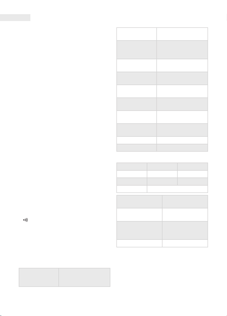
Baterie
9 V 6F22 sau tip NEDA
1604
Valoare max. : 1999
Aşaj
Prelevare de probe: 2-3/
secundă
Procedura de
măsurare
Aşarea
suprasarcinii
Aşarea polarităţii
Temperatura de
lucru
Temperatura de
depozitare
Aşare Baterie
descărcată
Convertor A/D Dualslope
Apare numai „1” pe aşaj
'-' indică polaritatea
negativă
0 °C-40 °C (32 °F-104 °F)
-10 °C-50 °C
(10 °F-122 °F)
Textul 'BAT' apare pe
aşaj
Mărimi 230mm x 90mm x 37mm
Greutatea cca. 320 g (cu baterie)
Curent AC
Domeniu Rezoluţie Observaţii
200 A 100 mA
1000 A 1A < 800 A
Acurateţe +/-2.0% +/- 5d
Test de continuitate
• Conectaţi cablul de testare roşie la banana 'VΩ'
, iar cel negru la 'COM'.
• Setaţi comutatorul de funcţii la poziţia
„ ” .
• Atingeţi vârful cablurilor de testare la cele
două puncte al circuitului ce va testat. Dacă
circuitul nu este întrerupt (R< 50Ω), difuzoraşul
încorporat va scoate un semnal sonor.
Descriere
• Acurateţea la 23 °C+/-5 °C, la umiditatea relativă
mai puţin de 80%.
Tensiune maximă
între banane şi sol
(GND)
1000V DC sau 750 V AC
RMS (sinusoidal)
Domeniul de
frecvenţă
Protecţia împotriva
suprasarcinii
50 Hz– 60 Hz
1200 A, până la 60
secunde
medie, certicată cu
Valoarea semnalizată
semnal sinusoidal
(RMS)
Deschiderea fălcilor 5 cm
Page 13
Manual de utilizare
RO
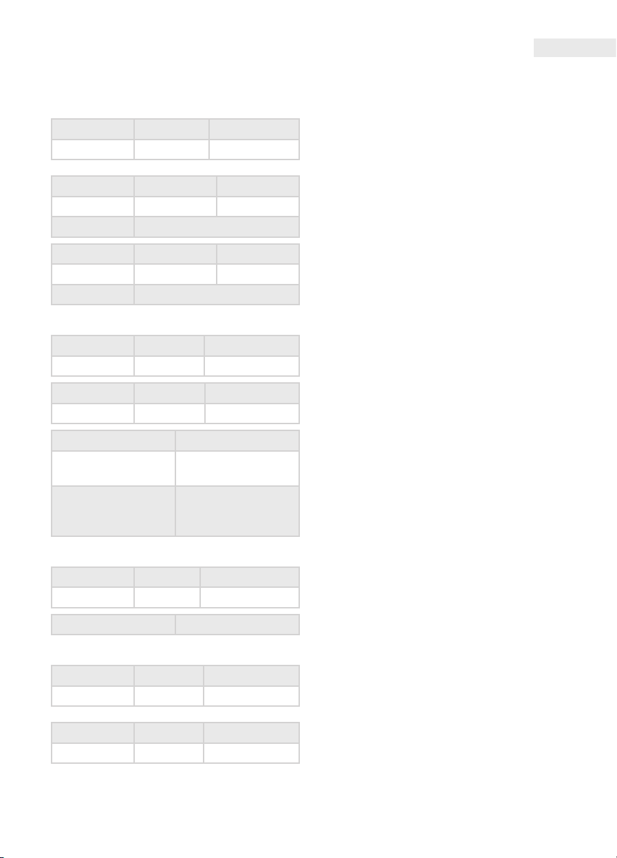
Test de izolare
Cu tester de izolaţie exterioară 500 V
(nu este în dotare)
Domeniul Rezoluţia Acurateţea
20 MΩ 10 kΩ +/- 2.0% +/- 2d
Domeniu Rezoluţie Observaţii
2000 MΩ 1 MΩ < 500 MΩ
Acurateţea +/- 4.0% +/- 2d
Domeniu Rezoluţie Observaţii
2000 MΩ 1 MΩ < 500 MΩ
Acurateţea +/- 5.0% +/- 2d
Tensiune AC
Domeniul Rezoluţia Acurateţea
200 V 100 mV +/- 1,0% +/-4d
Domeniul Rezoluţia Acurateţea
750 V > 9 MΩ 1 V +/- 1,0% +/-4d
Impedanţa de intrare 9 MΩ
Domeniul de
frecvenţă
Valoarea semnalată
50 Hz–500 Hz
medie, certicată
cu semnal (RMS)
sinusoidal
accesorii
• Baterie (9V, 6F22 sau tip NEDA 1604)
• Cablu de testare (1per.)
• Instrucţiuni de folosire
scHiMBarea Bateriei
Dacă textul'BAT' apare pe aşaj, este cazul să
schimbaţi bateria. Slăbiţi şuruburile de pe partea
din spate a instrumentului şi deschideţi capacul.
Înlocuiţi bateria descărcată cu unul nou de acelaşi
tip. Asiguraţi-vă că polaritatea este corectă la
conectarea bateriei. Atenţie: Înainte de a scoate
capacul instrumentului, întotdeauna asiguraţivă că aţi deconectat cablurile de testare de pe
circuitul care urmează să e măsurat. Închideţi
înapoi capacul şi strângeţi şuruburile înainte de
instrumentul să e refolosită din cauza riscului
de electrocutare.
Tensiune DC
Domeniul Rezoluţia Acurateţea
1000 V 1V +/- 0,8% +/-2d
Impedanţa de intrare 9 MΩ
Rezistenţă
Domeniul Rezoluţia Acurateţea
200 Ω 0,1 Ω +/- 1,0% +/- 3d
Domeniul Rezoluţia Acurateţea
20k Ω 10 Ω +/- 1,0% +/- 1d
Page 14
Uživateľská príručka
SK
Bezpečnostná inforMácia
Tento prístroj je jedno prenosné, 3 1⁄2 digitové,
digitálne zámkové kliešte s LCD monitorom,
s funkciou testovania izolácie (s 500 V-ovou
jednotkou testovania izolácie (to nie je
príslušenstvo!))-opcia. Nasledujte bezpečnostné
informácie a návod na použitie, tak môžete zaistiť
bezpečné fungovanie a dobrý stav prístroja.
Pri používaní dodržte tieto bezpečnostné
normy:
• Ochrana proti nebezpečia elektrického prúdu.
• Chráňte prístroj pred neodborného
používania.
• Korešpondencia bezpečnostným noriem
je garantovaný len v bezpochybnom stave
meracích šnúr. V prípade poškodenia ich ihned
vymeňte na taký istý typ.
Upozornenie
• Neprekročujte hodnotu preťažovania uvedenú
v návode na použití v žiadnej hranici merania .
• Ked sa s prístrojom pripojíte na prúd merania,
nedotýkajte sa nepoužívané spodky.
• Ak nepoznáte …meraného množstva, nastavte
spínač výber funkcie na najvyššiu hranicu
merania.
• Pred zmenou funkcie zrušte kontakt s prúdom
merania.
• Pri meraní TV a spínací obvodu prúdu budte
opatrný, lebo impulzy napätia s veľkou
amplitúdou, ktoré sa vyskytnú na testovaných
bodov môžu prístroj zničiť.
• Nemerajte odpor v prude pod napätím.
• Budte opatrný pri meraní napätia vyššieho ako
60 V DC alebo 30 V AC (RMS). Držte prsty za
bariérou hmatadla. Nedotýkajte sa kovového
kontaktu hmatadla
dalej prístroj nepoužívajte, a bezpodmienečne
ho dajte opraviť s odborníkom.
• Nikdy nepoužívajte prístroj, ak pokrývka
batérie nie je na mieste alebo nie je perfektne
xovaný.
• Nečistite zaridenie s miernou čistiacou
prostriedkou.
fUnkcie
• Meranie prúdu AC – testovanie izolácie (opcia)
• Meranie napätia DC a AC
• Meranie odporu
• Test kontinuity
kontrolky
1
3
2
4
5
Symboly upozornenia:
• Nebezpečenstvo/dôležitá informácia
• Symbol korešpondencie (norme EU)
• "COM" Zem (GND)
ÚdržBa
• Pred otvorením zábalu prístroja vždy zrušte
kontakt s prúdmi pod napätím.
• Ak zistíte akúkoľvek chybu alebo nepravidelnosť,
6 7
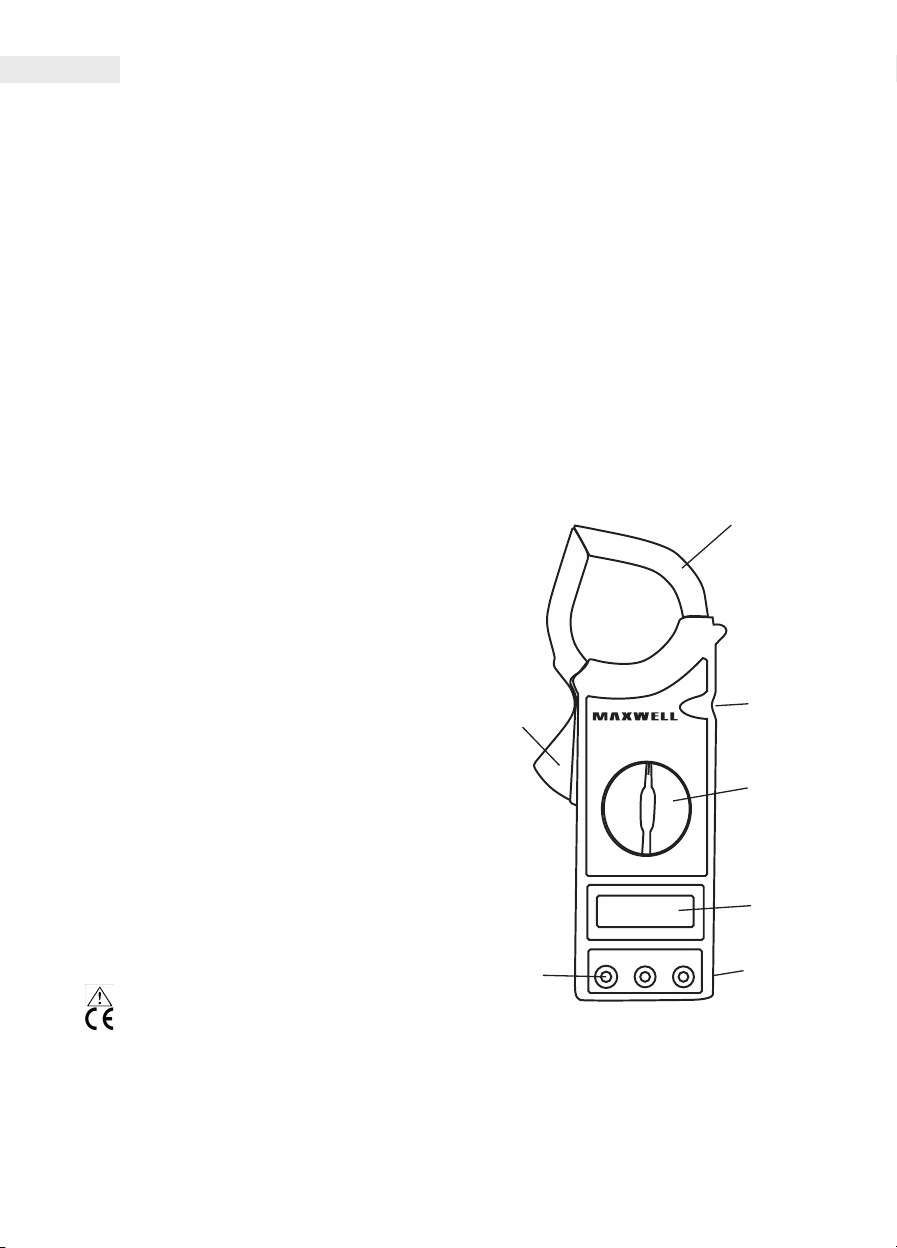
1. Transformátor sponky
2. Tlačidlo odomknutia
3. Tlačodlo 'HOLD'
Stlačením tlačidla na monitore zostane práve
meraná hodnota, kým znova netlačíte tlačidlo
(funguje pri každej funkcie.)
Page 15
Uživateľská príručka
SK
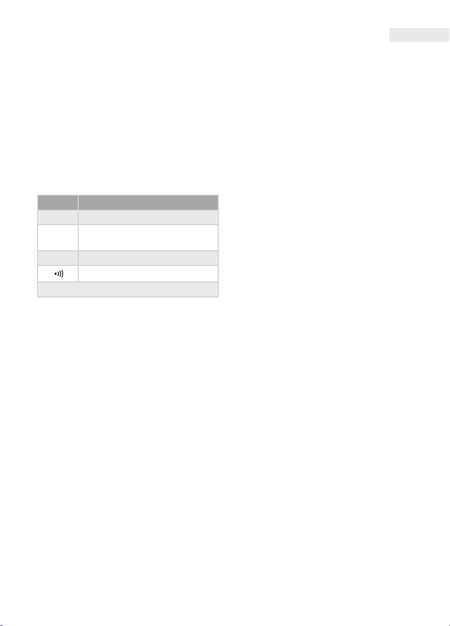
4. Tlačidlo funkcia a limit merania
S týmto tlačidlom môžete vybrať požadovanú
funkciu a limit merania. Zastavením spínača do
OFF, prístroj môžete vypnúť.
5. Monitor LCD
6. Vstupné konektory
Na prístroje sa nachádzajú 3 vstupné konektory.
Tieto obsahujú ochranu proti preťaženiu do
limit dané v tabuľke. Pri meraní pripojte čiernu
meraciu šnúru do zásuvky 'COM', a červenú do
zásuvky 'VÙ'.
7. Držiací opasok
Funkcia Vstupné limitné hodnoty
200 mV 250 V DC alebo AC RMS
DC V a
AC V
1000 V DC, 750 V AC (sinusový)
Ω 250 V DC alebo AC RMS
250 V DC alebo AC RMS
Pripojenia červene zásuvky: VΩ
Spodka 'EXT' slúži na pripojenie testovania izolácie
(vonkajšie banánikové zástrčky), pri meraní odporu
izolácie.
poUžívanie
Meranie prúdu
• Nastavte spínač funkcie na vhodnú hranicu
merania AC A. Spony transformátora pripínajte
na vodič prechádzaný striedavým prúdom.
• Ak na monitore vidíte len signál '1' , to znamená
preťažovanie, vtedy napnite na vyšší limit
merania.
Testovanie izolácie
• Pripojte banánikové zástrčky 'VΩ', 'COM', 'EXT'
testovanie izolácií do zásuvky 'VΩ', 'COM', 'EXT'
zámkovej kliešti.
• Nastavte spínača funkcie zámkovej kliešte do
pozície 2000 MÙ.
• Nastavte spínača meracieho limita testovacej
izolácií do pozície 2000 MΩ.
• Pripojte hmatadlo na vstupy 'L' a 'E' testovača.
Pritom tester musíbyť vypnutý.
• Nastavte tlacidlo testovača 'POWER' do 'ON'.
• Stlačte tlačidlo PUSH 500V, vtedy svieti lampa
so signálom 500V . Na monitore zámkovej
kliešte vidíte hodnotu odporu izolácií. Ak
meraná hodnota je menšia ako 19 MΩ, nastavte
zámkové kliešte do20 MΩ.
• Ak tester nepoužívate, vypnite ho a vytiahnite
meracie šnúry zo spodkov 'E' a 'L' . s tým môžete
zvýšiť životnosť batérie a znížiť nebezpečie
úrazu prúdom.
(s pripojením 500 V-ovej jednotky-nie je príslušenstvo)
Meranie napätia
• Pripojte červený konektor do 'VΩ' , a čierny do
'COM'.
• Nastavte spínač funkcie do vhodného AC V
alebo DC V.
• Pridajte hmatadlá k napätiu merania, a hodnota
napätie sa objaví na monitore (pri meranie
napätie DC prístroj signalizuje polaritu červenej
hmatadla)
• Ak sa na monitore objaví len nápis '1', to
znamená prťaženie, nastavte spínač funkcie na
vyššiu hranicu merania.
Meranie odporu
• Pripojte červený konektor do zásuvky 'VΩ', a
čierny do zásuvky 'COM'. (polarita červenej
meracej šnúry je: '+'.)
• Nastavte spínač funkcie do vhodnej pozície
odporu.
• Pridajte hmatadlá k odporu , a na monitore sa
objaví meraná hodnota.
• Ak hodnota odporu je väčšia ako maximálna
hodnota vybranej limitu merania alebo na
výstup nepripojíte odpor, na monitore sa objaví
'1'.
• Ak odpor je súčasťou prúdu, vypnite
napätie silu a vybite každý kondenzátor
pred pripojením k prístroju.
Test kontinuity
• Pripojte červený konektor do zásuvky 'VΩ', a
čierny do zásuvky 'COM'.
• Nastavte spínač funkcie do pozície ???.
• Pripojte hmatadlá na dve body prúdu merania.
Ak prúd nie je roztrhaný (R< 50Ω), zastavaná
píšťaľa vydáva zvukový signál.
Opis
• Presnosť, pri 23 °C+/-5 °C, a v prípade relatívnej
vlhkosti vzduchu menej ako 80 percent.
Page 16
Uživateľská príručka
SK
Maximálne
napätie medzi
spodmi a GND
Baterka
Monitor
Merací postup
Preťažovanie
Polarita
Prevádzková
teplota
Skladovacia
teplota
Nízke napätie silu
Rozmery 230mm x 90mm x 37mm
Váha o. 320 g (s baterkou)
AC prúd
Limit merania Rozlíšenie Poznámka
200 A 100 mA
1000 A 1A < 800 A
Pontosság +/-2.0% +/- 5d
Frekvencia 50 Hz– 60 Hz
Ochrana proti
preťažovaniu
Signalizovaná
hodnota
Otvor sponiek 5 cm
1000V DC alebo 750 V
AC RMS (sinusový)
9 V typu 6F22 alebo
NEDA 1604
max. érték: 1999
Frissítés: 2-3/másodperc
Dual-slope A/D
konverter
Na monitore sa objaví
len „1”
A '-' signalizuje
negatívnu polaritu
0 °C-40 °C (32 °F-104 °F)
-10 °C-50 °C
(10 °F-122 °F)
Na monitore sa objaví
nápis 'BAT'
1200 A, do 60 sekúnd
priemer, certikované
s oznakom sinusa
(RMS)
Testovanie izolácie
S vonkajším 500 V-ovým testerom
( nie je príslušenstvo)
Limit merania Rozlíšenie Presnosť
20 MΩ 10 kΩ +/- 2.0% +/- 2d
Limit merania Rozlíšenie Poznámka
2000 MΩ 1 MΩ < 500 MΩ
Presnosť +/- 4.0% +/- 2d
Limit merania Rozlíšenie Poznámka
2000 MΩ 1 MΩ < 500 MΩ
Presnosť +/- 5.0% +/- 2d
AC prúd
Limit merania Rozlíšenie Presnosť
200 V 100 mV +/- 1,0% +/-4d
Limit merania Rozlíšenie Presnosť
750 V > 9 MΩ 1 V +/- 1,0% +/-4d
Vstupná impedancia 9 MΩ
Frekvencia 50 Hz–500 Hz
Signalizovaná
hodnota
DC napätie
Limit merania Rozlíšenie Presnosť
1000 V 1V +/- 0,8% +/-2d
Vstupná impedancia 9 MΩ
Odpor
Limit merania Rozlíšenie Presnosť
200 Ω 0,1 Ω +/- 1,0% +/- 3d
priemer,
certikovaný s
oznakom sínusa(RMS)
Limit merania Rozlíšenie Presnosť
20k Ω 10 Ω +/- 1,0% +/- 1d
Page 17

príslUšenstvo
• baterka (9V, typu 6F22 alebo NEDA 1604)
• meracia šnúra (1pár)
• návod na použitie
výMena Baterky
Ak sa na monitore objaví nápis 'BAT', to znamená
že baterku treba vymeniť. Uvolnite skrutky na
zadnej strane prístroju a otvorte zábal. Vymeňte
vybitú baterku na novú baterku s takým istým
typom. Dajte pozor na pripojenie so správnou
polaritou. Upozornenie: predtým že by ste
odstránili zábal prístroja, vždy sa presvedčte
o tom, či ste odpojili meracie šnúry z prúdu
merania. Púzdro zavrite naspäť a stiahnite
skrutky predtým že by ste prístroj znovu použili
kvôli nebezpečenstva úrazu prúdom.
Uživateľská príručka
SK
 Loading...