

Maxwell Automation FT200, FT204, FT205, FT209, FT207 User Manual
LCD display advanced digital temperature controller
User Manual
FT20X- 800-C1
Please r ead this ma nual care fully and k eep this ma nual for fu rther ref erence
Fea tures
LCD t hree co lor VA dis play, bar gra phic,outp ut perc entage MV 1/MV2 o r feedb ack MVF b displ ay
0.2 % measu ring ac curac y, max imum reso lutio n 0.1 for TC and RTD i np ut
Out put: relay, SSR dr ive, analo g, triac,re- trans missi on
Ala rm:AL 1/AL2 r elay ou tput, exci tation, non-ex citatio n, delay outpu t, alarm loc k funct ion
Ala rm mode : PV, deviation, absolu te, band, alarm sta ndby, PV de viation a larm ra mp
sta rt-up a larm, ramp e nd alar m, Loop break al arm,h eater bre ak alar m
Con trol mo de: PID with a uto-t uning , on/ off, heating or co oling , hea ting+co oling , 3 wir es
pro porti onal va lve con trol, valv e contr ol with f eedba ck sign al, output res train
Pro gram ve rsion : PID m ode, ramp up m ode, temp cons tant mo de, soft-s tart
Add -on fea ture: auto/m anual c ontro l, run/stop fu nctio n, even SV inp ut
Spe cial fe atures: all pa ramet ers dis tribu ted in th ree lev els, paramet ers can b e manua lly
des ignate to d iffer ent lev el
Com munic ation: RS-48 5, modbus-RT U, pa ttern 8 -(N,O ,E)-( 1,2)
Amb ient te mp 0-50 C, humid ity 0-8 0%RH
0
1: Model number and ordering information
Ple ase che ck this o rderi ng info rmation a nd spec ify the c ode whe n order w ith us
Mod el
Ite m numbe r( Pane l si ze: wid th x heig ht)
FT200 (48mm*48mm)
FT204 (48mm*96mm)
FT205 (96mm*48mm)
FT207 (72mm*72mm)
FT209 (96mm*96mm)
Ver ti cal
Hor izont al
:RS-485 Communication
7
N No commu nicat io n fea tu re
K RS-485 m odbus RTU com mu nicat ion
:AUX po wer source
8
N No aux pow er
A 24Vdc is olate d
:Position feedback(analong feedback input from INP2)
9
N No posit ion feedb ack
C 0-5Vdc /potent iomter
:Remote SV setting
10
N No remot e SV feat ur e
C 0-5Vdc v ia INP2
F 4-20mA v ia INP3
J 1-5Vdc v ia INP3
:Manual output% remote setting
11
N No remot e SV feat ur e
C 0-5Vdc v ia INP2
G 0-20mA v ia INP3
B 24Vdc gr ounded
D 12Vdc gr ounded
C 12Vdc is olate d
A 4-20mA
D 1-5Vdc
A 4-20mA v ia INP2
D 1-5Vdc v ia INP2
G 0-20mA v ia INP3
K 0-10Vd c via INP3
W D1/D2 te rminals e vent inpu t
A 4-20mA v ia INP2 B 0-20mA v ia INP2
E 0-10Vd c via INP2
H 0-5Vdc v ia INP3
B 0-20mA
E 0-10Vd c
B 0-20mA v ia INP2
E 0-10Vd c via INP2
H 0-5Vdc v ia INP2
F 4-20mA v ia INP3
K 0-10Vd c via INP3
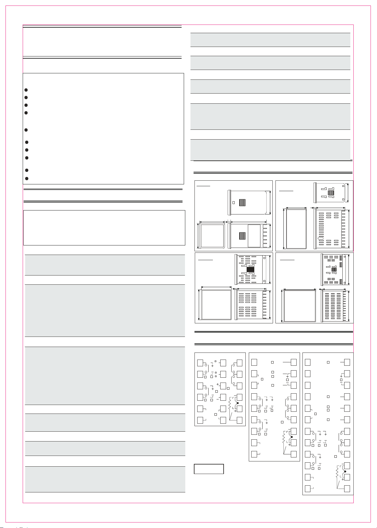
2. Size and mounting
FT2 00
Uni t:mm
48 68.4
48
7
FT2 04
FT2 05
Uni t:mm
44.644.6
48
96
44.6
68.47
91.2
:Controller type
1
U
Standa rd PID type
R Ramp a nd soak mod e(with ti mer)
X Motor v alve dire ct/reve rse contr ol versio n(two rel ays)
:OUTPUT 1
2
R
V
Relay ou tput
SSR Driv e/Vo ltage p ulse outp ut
D 4-2 0m A outpu t
E
0-10Vd c
F 0-20mA
5 0-5Vd c
7 1-5Vd c
T Traic si ng le phas e ze ro-cr os sing tr ig ger
A Re lay out pu t, for m ot or valve dire ct act cont rol
:OUTPUT 2(output 2 is only available for heat in g+ co ol in g co nt ro ll er )
3
N No ou tp ut2( For sing le output c ontroll er, choose code N )
R
V
Relay ou tput
SSR Driv e/Vo ltage p ulse outp ut
D 4-2 0m A outpu t
E
0-10Vd c
F 0-20mA
5 0-5Vd c
7 1-5Vd c
T Traic si ng le phas e ze ro-cr os sing tr ig ger
A Re lay out pu t, for m ot or valve reve rse act con trol
4
:Number of Alarms
1
2
3
:Power Source
5
1 alarm
2 alarms
3 alarms
96 85~26 5Vac 5 0/60H Z
24 24Vac/2 4V dc
:PV/SV re-transmission
6
N No re-tr ansmiss ion funct ion
A 4-20mA r e-trans mission v ia OP2
B 0-20mA r e-trans mission v ia OP2
E 0-10Vd c re-tran smissio n via OP2
FT20X-800-C1
F 4-20mA r e-trans mission v ia AU3
G 0-20mA r e-trans mission v ia AU3
K 0-10Vd c re-tran smissio n via AU3
FT2 07
Uni t:mm
72
72
3. Wiring diagram
FT 20 0
OP2
1
2
OP1
3
4
L
5
AC
85~265V
6
N
Mai n outpu t Relay
250 Vac 5A( re sistive l oad)
Ala rm rela y
250 Vac 3A( re sistive l oad)
4-2 0mA out put(m aximu m load
res istan ce 500 oh m)
12V DC puls e outpu t( 20mA )
Remark
AL1
AUX+
13
7
AUX+5V
A+
RS-485
B-
INP2
8
14
15
9
AL2
A
1016
mA
TC
V
17
11
B
B
18
12
Abo ve is a gen eral wi ring di agram, pleas e
alway s refer t o the con necti on diagra m on
the s ide of th e contr oller
INP 2/INP 3 used fo r remot e SV, or po sitio n
fee dback o r remot e outpu t% unde r manua l
mod e,Ple ase ref er to wir ing dia gram on the
uni t for sin gle pha se or thr ee phas e triac o utput
opt ion
68.47
FT207
1
2
RS-485
3
4
5
6
7
8
85~265V
9
OP1
L
N
A+
B-
OP2
FT2 09
Uni t:mm
91.2
96 68.47
67.2 67.2
96
FT 20 4/ FT 20 9/ FT 20 5
INP2+
10
1
GNDAUX-
AUX+
AU3
AL1
TRS
AL2
A
mA
V
AC
B
B
TRS
11
12
13
14
15
16
17
18
2
3
4
A+
5
RS-485
6
B-
OP2
TRS
7
TC
8
OP1
9
10
L
11
AC
85~265V
12
N
INP3+
INP2+
GNDAUX-
AUX+
AU3
AL2
AL1
mA
91.2
13
14
TRS
15
16
17
18
19
20
21
A
22
TC
V
23
B
B
24
1
4. Panel description
48mm 96mm
72mm 72mm
SV1
SV2
SV3
SV4
ATU
AU1
AU2
OP1
48m m 48m m
SV1
SV2
SV3
SV4
PV
ATU
OP1
OP2
MAN
AU2
AU3
AU1
COM
PRG
OP1
OP2
AU1
AU2
ATU
COM
SET
PV wi ndow:di splay P V and par amete r notatio n
SV wi ndow:di splay S V and par amete r value
Bar g raphic: indi cate output %,fee dback v alue
or re -tran smiss ion val ue
OP1 : Ind icate OP1 s tatus
OP2 : Ind icate OP2 s tatus
ATU: In dicate auto -tuni ng status
AU1 : AL1 alar m status
AU2 : AL2 alar m status
AU3 : Res erve d light
MAN : Man ual con trol/ soft- start i ndica tion
COM : Com munic ation ind ication
PRG : Temp co ns ta nt mode i ndica tion
Ram p and soa k indic ation
10 20 30 40 50 60 70 80 90 100
MAN
SV
PRG
F3
F1F2
FT200
F3
A/M
SET
OP2
AU3
COM
PRG
MAN
10 20 30 40 50 60 70 80 90 100
A/M
F3
F1
F2
FT207
FT204
SET
96mm 96mm
SV1
SV2
SV3
SV4
ATU
OP1
OP2
MAN
AU1
AU2
AU3
COM
PRG
10 20 30 40 50 60 70 80 90 100
F3
F1F2
A/M
SET
SET: Ma in f un ction k ey
A/M :Auto /manu al switch k ey and en ter key
:Sh ift key (F3 fun ction k ey, such as ATU fas t initi ated
or go b ack to pr eviou s param eter)
:Nu meric d ecrea se(F2 f uncti on key)
:Nu meric i ncrea se(F1 f uncti on key, Run /Stop )
SV1 : Eve nt inpu t SV1 ind ication
SV2 : Eve nt inpu t SV2 ind ication
SV3 : Eve nt inpu t SV3 ind ication
SV4 : Eve nt inpu t SV4 ind ication
SV1 a nd SV2 li ght tog ether i ndica te remote -SV
FT20 9
F1F2
FT205
SV1
SV2
SV3
MAN
SV4
PRG
OP1
OP2
10 20 30 40 50 60 70 80 90 100
96mm 48mm
ATU
AU1
AU2
AU3
COM
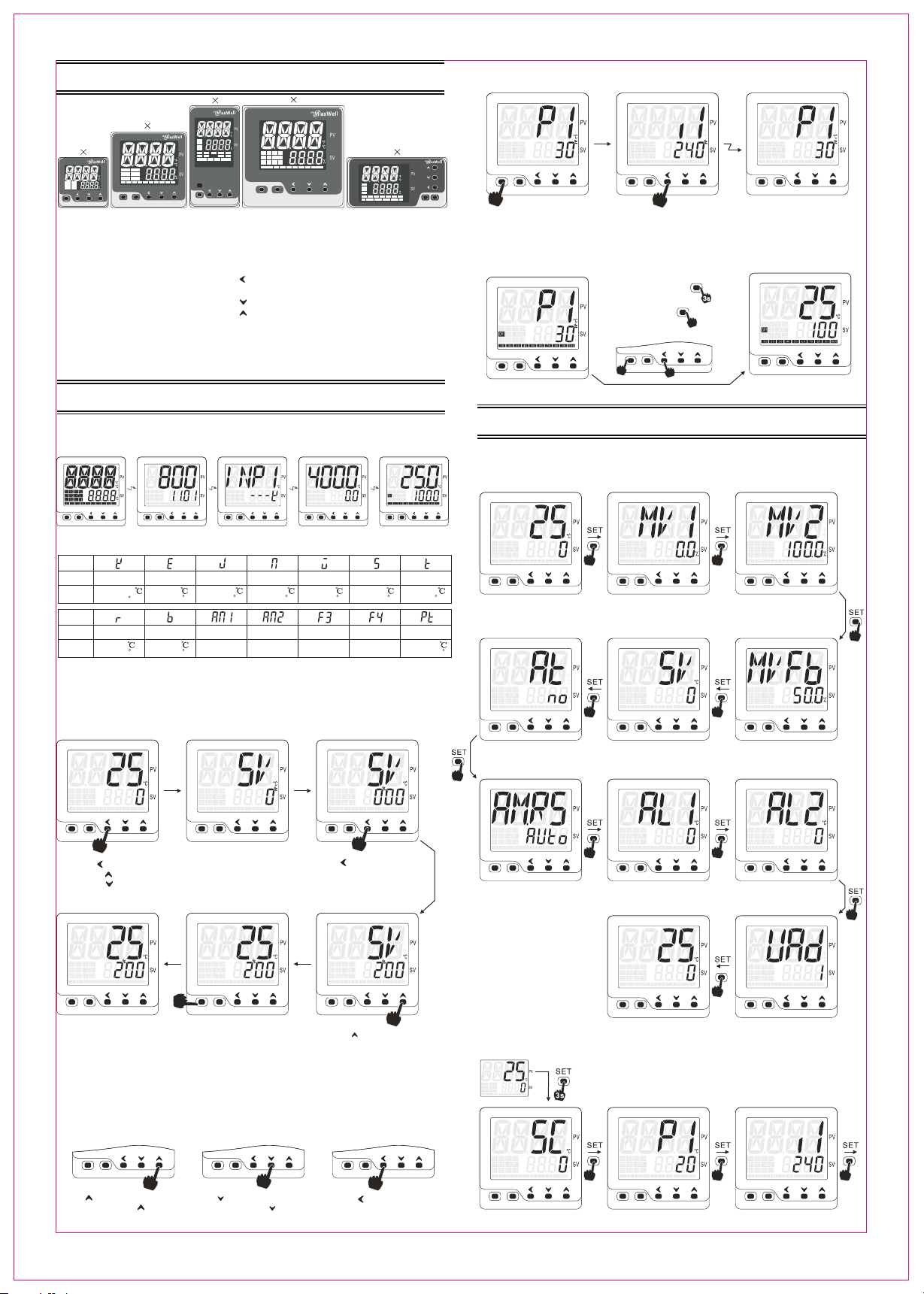
5. Setting and programming
5.1 Power on initi ali zat ion
Pow er o n st ag e sh ow s the softw are ver sion an d editi on, input ty pe and se tting v alue ra nge
MAN MAN MAN MAN MAN
PRG PRG PRG PRG PRG
F3 F3 F3 F3 F3
F1 F1 F1 F1 F1
F2 F2 F2 F2 F2
A/M A/M A/M A/M A/M
SET SET SET SET SET
Powe r on
all LE D and ind icato rs
ligh t up
autom atci di splay
Soft ware ve rsion
Soft ware ed ition
Nota tion
Sens or type
Rang e
K
-15 t o 130 0
0 to 2600
F
E
-15 to 800
0 to 1560 F
Nota tion
Sens or type
Rang e
r
0 to 1769
0 to 3216 F
b
0 to 1800
0 to 3276 F
5.1 SV c onfiguration and paramet er configuration
5.2.1 Ho w to chan ge t he SV set ti ng valu e, use the s ho rt cut ke y.
For e xa mple: change t he SV fro m 0 to 200 C
(1) P V/SV di splay m ode
MAN
PRG
autom atci di splay
Inpu t senso r type
such a s K therm ocoup le
J
-15 to 1000
0 to 1950 F 0 to 2600 F 0 to 3276 F 0 to 3000 F 0 to 782 F
DC0-50mVNDC10-50mV
-1999 to 9999 -1999 to 9999
autom atci di splay
SV set ting va lue ran ge
such a s 0.0~4 00.0
-15 to 1300 0 to 2200 0 to 1600 -15 to 400
Wu3_Re25 S t
Rese rved
Rese rved
0
autom atci di splay
Rese rved
Rese rved
Norm al disp lay sta tus
Uppe r PV and lo wer SV
(2) S V confi gurat ion par amete r (3) S V confi gurat ion mod e
MAN MAN
PRG PRG
F1
F2
F3
A/M
SET
Pt100
-199 to 800
-326 to 1472 F
5.2.3 Sh ift betwe en parame ters and go b ack to prev ious para meter
(1) P 1 param eter in terfa ce (2) i1 para meter i nterf ace (3) P1 para meter i nterf ace
Goe s
MAN
PRG
F3
F2
A/M
SET
Pre ss SET ke y once
at an y param eter to g o to
nex t param eter
Shi ft to
MAN
PRG
F1
SET
Pre ss F3 key a nd hold t o go
bac k to prev ious pa ramet er
F3
A/M
bac k
MAN
PRG
F2
F1
A/M
SET
Go ba ck to pre vious p arame ter
in th is case , P1 to i 1 and bac k to P1
5.2.4 Sa ve conf ig ura ti on and go b ac k to norm al P V/SV di sp lay mod e
(1) P 1 param eter in terfa ce
MAN
PRG
F3
A/M
SET
Thr ee appr oache s
1. Pre ss SET fo r 3 secon ds
2. Pre ss A/M key o nce
3. Pre ss SET an d F3 toge ther fo r once
F2
F1
SET
Sav e and exi t to PV/S V displ ay mode
SET
A/M
F3
F2
A/M
F1
MAN
PRG
A/M
SET
6. Parameter menu
6.1 Fact ory default p ara meter menu
6.1.1 Qu ick start m enu level 1 (Press SE T once to ent er this men u)
Mor nitor ing par amete r MV1
MAN
PRG
F3
F2
A/M
SET
PV/ SV mode
Pre ss SET on ce
MAN
PRG
A/M
SET
Aut o-tun ing swi tch(F 02 grou p)
No au to-tu ning of f
Yes aut o-tun ing on
F1
F3
F2
F1
Out put1% v alue di splay p arame ter
MON I under m enu PASS -0303 i s
use d for def ining t he stat us of MV1 ,
whe ther pr esent t his or hi de this
MAN
PRG
F3
A/M
SET
MAN
PRG
F3
A/M
SET
Set ting va lue par amter
(Un der F00 m enu gro p)
F2
F2
Mor nitor ing par amete r MV2
MAN
PRG
F1
Out put2% v alue di splay p arame ter
MON I under m enu PASS -0303 i s
use d for def ining t he stat us of MV2 ,
whe ther pr esent t his or hi de this
F1
Posi tion fe edbac k varia ble dis play
MON I under m enu PASS -0303 i s used fo r
def ining t he stat us of MVF b, wheth er
pre sent th is or hid e this
F3
A/M
SET
MAN
PRG
F3
A/M
SET
F3
F2
F1
F3
F2
F1
F2
F1
F2
F1
F3
F2
A/M
SET
Pre ss once
or pr ess onc e
or pr ess onc e
(6) P V/SV di splay m ode
Con figur ation f inish
bac k to PV/S V displ ay
mod e
Rem ark 1: SV sett ing par amete r can be as signe d to diff erent p arame ter men us, refert o S.F00
par amete r for det ails
Rem ark 2: SV remo te sett ing det ails, refer to “10. SV remot e setti ng for mo re info rmation ”
F1
Upp er disp lay sho ws SV
low er show s the cur rent
SV va lue, wit h the uni t’s digi ts
fla shing t he flas hing di gits
can b e modif ited
(5) S ave the c onfig urati on
Pre ss SET sa ve the co nfigu ratio n
or pr ess A/M ke y save th e chang es
or co ntrol ler wil l goes ba ck to PV/ SV
if yo u put the c ontro ller id le for 3 se conds
F3 F3
F2 F2
A/M A/M
SET SET
MANMAN
PRGPRG
A/MA/M
SETSET
F1 F1
Pre ss key, mov e the
cur sor to th e hundr ed’s
dig its and f lashi ng
F3F3
F2F2
F1F1
(4) S V value m odifi ed
MAN
PRG
F3
A/M
SET
Pre ss key, cha nge the
hun dred’s d igit to “2 "
F2
5.2.2 Ho w to conf ig ure all c on figur ab le para me ters
Num eric in creas e Nu meric d ecrea se
F3 F3 F3
F2 F2 F2
A/M A/M A/M
SET SET SET
Pre ss key to i ncrea se the nu meric
of a pa ramet er, press a nd hold c an
fas t incre ase the v alue
F1 F1 F1
Pre ss key to d ecrea se the nu meric
of a pa ramet er, press a nd hold c an
fas t incre ase the v alue
2
Shi ft the fl ashin g digit s
Pre ss key to s hift th e
fla shing d igit
MAN
PRG
F3
F2
A/M
SET
AM. RS Cont rol mod e(F02 g roup)
Auto a uto con trol mo de
Man m anual c ontro l mode
Sto p stop mo de
Rem ark
PASS -0303 m enu is an e ngine er menu
pas sword i s 0303, re fer to 6. 4 for det ails
F01 -F08 is p arame ter gro up, some o f
par amete rs were a ssign ed to F01 -F08
gro up, by con figur ing par amete r S.F01 -
F1
S.F 08, you ca n assig n diffe rent
par amete rs to be pr esent ed in qui ck
sta rt menu o r not, ref er to 6.2 f or more
det ails
F1
MAN MAN
PRG PRG
F3 F3
F2 F2
A/M A/M
SET SET
F1 F1
Ala rm 1 valu e(F02 g roup) A larm 2 va lue(F 02 grou p)
MAN
PRG
F3
F2
A/M
SET
F1
MAN
PRG
F3
F2
A/M
SET
Com munic ation a ddres s codePV/ SV disp lay mod e
F1
6.1.2 Qu ick start m enu level 2 (Press SE T for 3 secon ds to enter )
PV/ SV mode
MAN
PRG
Inp ut offs et
(F0 4 group )
Pre ss SET fo r 3 secon ds
A/MA/M
SETSET
P1: Pr oport ional b and of ou tput1
(F0 4 group )
MANMAN
PRGPRG
F3F3
F2F2
F1F1
i1: Integ ral tim e of outp ut1(F 04 grou p)
MAN
PRG
F3
F2
A/M
SET
F1
FT20X-800-C1
 Loading...