

Page 1
INSTRUCTION MANUAL
Air Curtains MAXWELL
SECURITY ADVISE SIMBOLS
Attention, Danger, Safety Advice!
Danger from electric current of high voltage!
Injuries risk!
Danger! Do not step underneath: Heavy load.
Important Information!
AIRDOM05131-R10(18/06/14)
Page 2
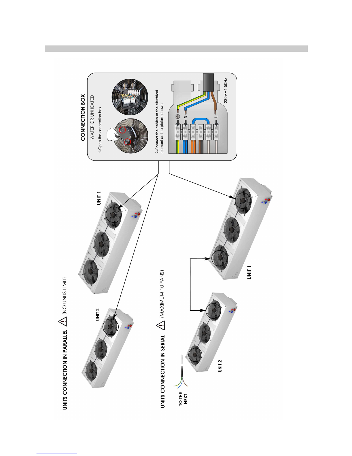
INSTALLATION DIAGRAM – (WITHOUT REGULATION)
Page 3
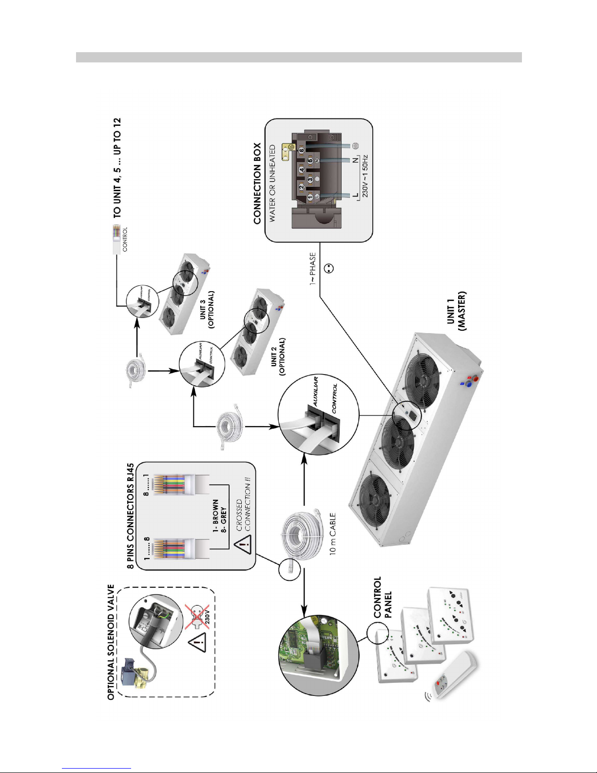
INSTALLATION DIAGRAM – (WITH REGULATION)
Page 4
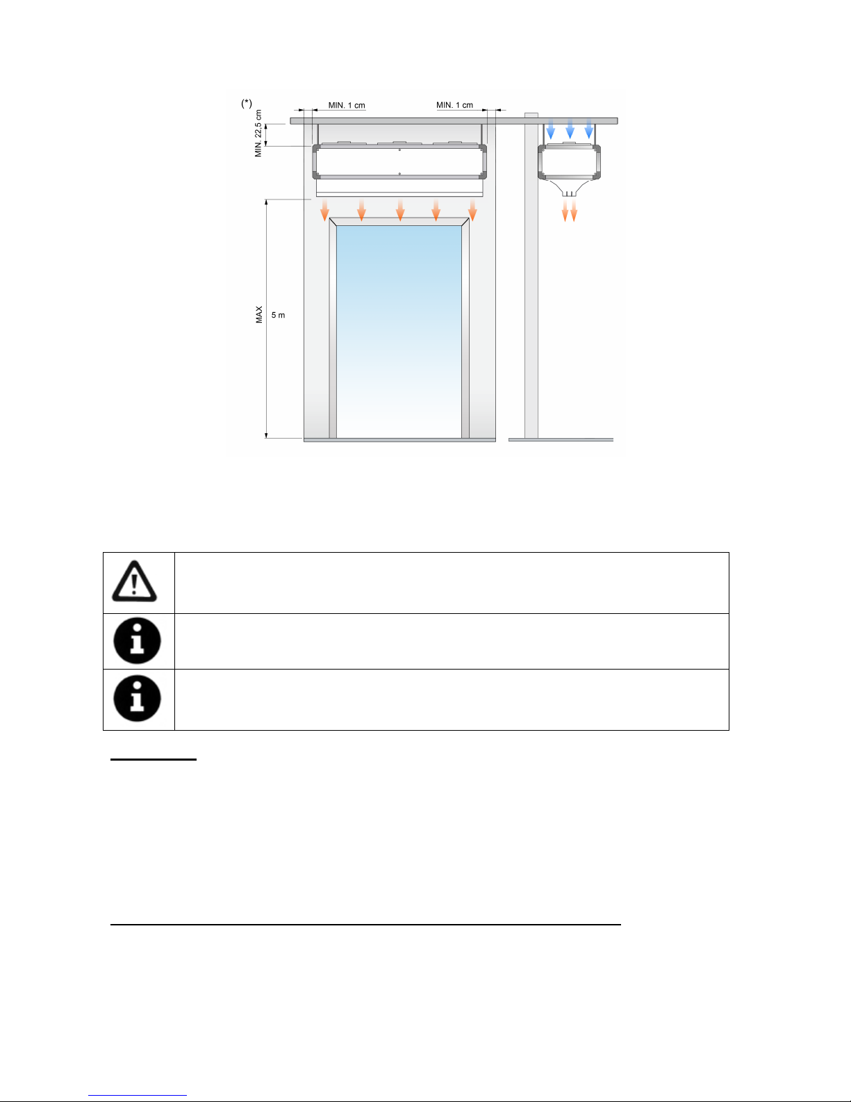
MAX. Maximum recommended height, MIN Minimum recommended distance
(*) Standard units. Under request this distance can be reduced to 1cm when connections are placed inside
and water pipes lateral.
Minimum recommended distance between the inlet grille and any obstacle is of 225mm.
Power Supply
To connect the power supply there is a black connection box in each fan of the air curtain (on the back).
Connection should be done directly in any black connection box at the ends of the air curtain.
For an ambient air or water heated air curtain, just connect the single phase 230Vx1.
In case of an air curtain with electrical heating we will also connect the three phase 400Vx3 of the electrical
element. Optionally under request the current of the electric battery can be three phases 230Vx3 or single
phase 230Vx1 depending on model (special wiring diagram will be enclosed).
PCBoard and control (Optional in case the air curtain has regulation incorporated)
To connect the controller there is a PCBoard (printed circuit) located outside the air curtain (on the back).
There is no need to open the unit to connect it.
Use the telephone cable of 10 meters (RJ45 connectors) supplied with the equipment. The communication
between the connector plate and the controller is digital through low-voltage.
Installation work, connection, disconnection, electrical wiring, mechanical maintenance and
service must be done by qualified persons observing these instructions and in accordance
with all applicable norms and standards.
If the unit is operated with additional controller, please consider its specific instructions.
There is no need to open the service door to connect the air curtain. All connections (power
supply, control, water pipes when existing) and fixations are external. They are placed on top
or lateral of the units. See how to open service door at repairs section.
For safety, the air curtains never have to be stopped by disconnecting from the main supply,
always through the controller and wait for 10 minutes at least to disconnect the main supply.
In case we do not follow these instructions, the internal parts of the air curtain can be
damaged.
Page 5
Optionally, there are available different accessories and controllers, to meet every customer’s needs (week
timer, thermostats, door contacts, anti-freezing sensor, supports, valves, etc…).
Fixing
Units are provided with several external suspension points, depending on the weight and length (see exact
situation of the points at the air curtains characteristics page).
Generally air curtains work horizontally but also can be installed vertically using feet (accessories section).
The anchor should be managed according to the weights of each unit shown on the technical data page. The
installation can be made through threaded rods, tensors or other supports. See available supports in the
accessories section.
Water coils
Water heated air curtains have a PCBoard with an output of 230Vx1 to install an electro valve (open/close
water entrance) or any other device. This output can also be used for other low amperage electric device (air
curtain option with regulation incorporated)
It is recommended:
• Close the warm water circulation (by closing the electro valve) to avoid motor overheating while the
unit is OFF. The electro valve is optional.
• Install 2 shut-off water valves (supply and return) in order to dismantle the equipment easily.
• Install a bleeding point at the highest part of the heating water circuit.
The ambient temperature should be always over +4ºC, otherwise it will be necessary to provide an anti-frost
protection device.
Water coils have a draining point placed at the end part of the intake manifold.
TRANSPORT AND STORAGE
Attention! Heavy load.
Do not step under hanging load during the transport or assembly.
Store in a dry place and weather protected in its original packaging. In case the packing is open, cover
the air curtain to protect it from dust. Do not step or put heavy load over the package to avoid damages to the
material. Store temperatures are between -20ºC and +40ºC.
When carrying material, make sure it is not damaged by the forklift (fork penetration in the packaging).
Please see the packaging instructions.
Page 6
L A
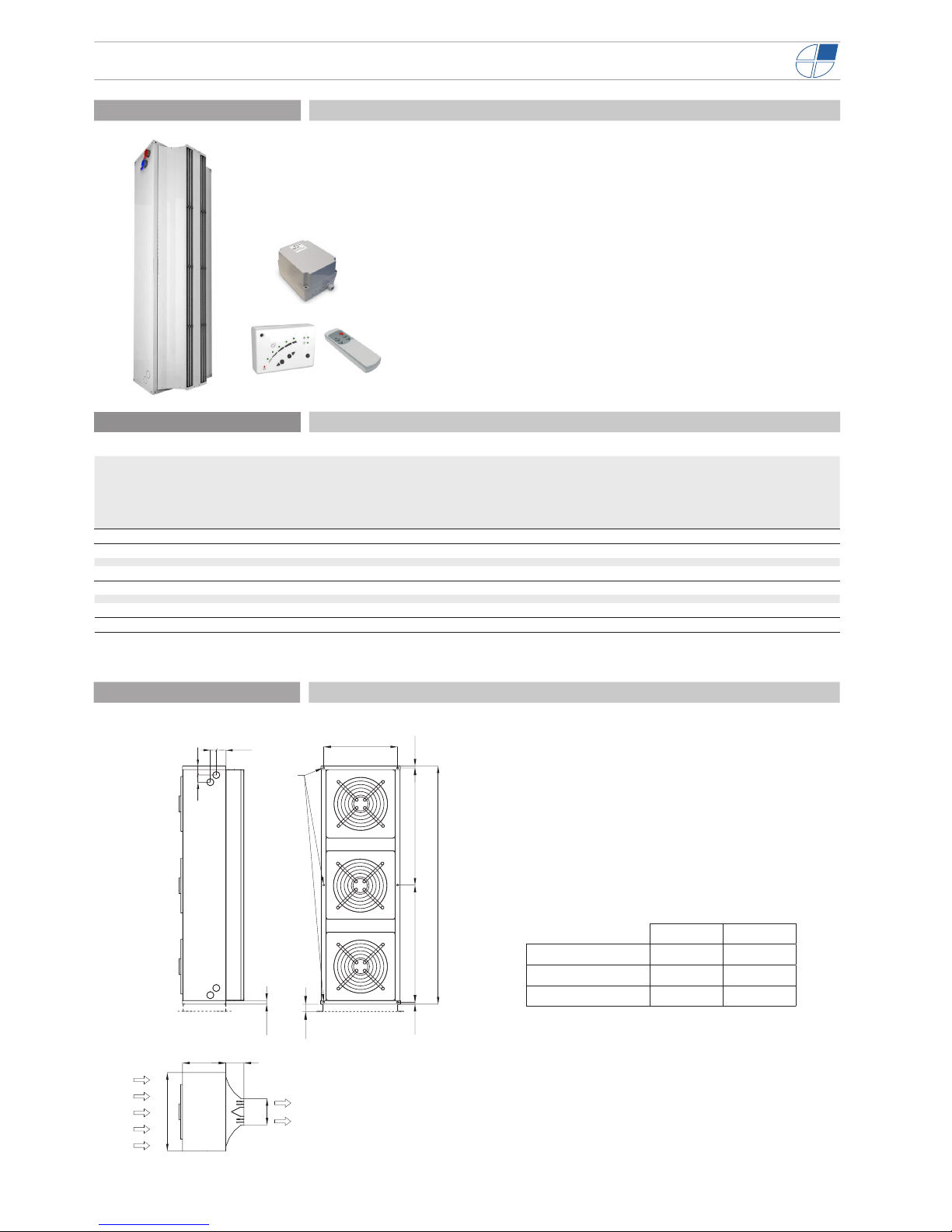
MXW 1500 1500 734
MXW 2000 2000 984
MXW 2500 2500 1234
Dimensions
30
615
660
361
150
222
6 x M8
1616
60
L
AA
7560
50
79,5
Model Airow
Water
heating
capacity
80/60ºC
Water drop
pressure
80/60ºC
Water
connections
80/60ºC
Water
heating
capacity
60/40ºC
Water
drop
pressure
60/40ºC
Water
connections
60/40ºC
Fans
power
230V-50Hz
Fans current
230V-50Hz
Noise
level
(5 m)
Weight
m3/h kW Pa kW Pa kW A dB(A) kg
MXW 1500 A 8000 - - - - - - 0,68 2,96 59 79
MXW 1500 P 7000 40,85 14.770 2x1¼” 32,82 15.440 2x1¼” 0,68 2,96 59 95
MXW 2000 A 12000 - - - - - - 1,02 4,44 61 103
MXW 2000 P 10500 60,66 14.260 2x1¼” 47,87 14.690 2x1¼” 1,02 4,44 61 126
MXW 2500 A 16000 - - - - - - 1,36 5,92 62 126
MXW 2500 P 14000 78,53 14.690 2x1¼” 63,58 17,950 2x1¼” 1,36 5,92 62 158
MAXWELL | Air Curtains For Industrial Doors
• High performance heavy duty industrial air curtains for vertical and horizontal installations, available in 1.5, 2.0 and 2.5 meters length. Easy dockable modules to
reach large dimensions.
• Self-supporting galvanized steel plate housing, powder-coated in white RAL 9016
as standard.Other colors are available on customer request.
• High efciency and low noise axial fans driven with external rotor motor, single
phase 230V/50Hz. Optionally three phase 400V/50Hz
• Ambient models “A”, without heating and warm water heated models “P” up to
120ºC.
• Double outlet with Coanda effect to achieve larger and efcient air jet. Adjustable
pitch angle outlet vanes, airfoil shaped.
• Different control options, from simple on/off to full automatic: 2/5 ventilation speed,
manual or automatic functioning, remote control, with telephone cable and fast
connectors (Plug and Play), interface to connect to BMS, etc...
Characteristics
Specications
Electrical heated models available on customer request. Let us know your needs
Page 7

OPERATING INSTRUCTIONS
For safety, the air curtains never have to be stopped by disconnecting from the main
supply, always through the controller and wait for 10 minutes at least to disconnect the
main supply. In case we do not follow these instructions, the internal parts of the air
curtain can be damaged.
Control PCBoard characteristics (optional if the air curtain has regulation incorporated)
It adjusts the fan speed through the input voltage variation of the set of fans. The PCBoard has 5 output
voltages: 120, 140, 170, 200 and 230 Volts.
Controller’s common characteristics
• Controllers: There are several models depending on the customer’s needs (timers, anti-freeze
detectors, thermostats, etc...).
• 5 ventilation speeds
• Memory: It guarantees that in the event of a power shortage, the selected speed will be maintained
when the service is re-established. This function can be connected-disconnected through the switch
ON/OFF placed inside the controller.
• Telephone cable and digital communication: “Plug and Play” easy and fast connection through
telephone cable and digital communication between the controller and the air curtain. This kind of
communication is more reliable even at long distances.
• External ON/OFF: Inside the controller there is a normally open contact (1,2) that controls the
ON/OFF of the equipment through any external device. The contact is potential-free. When the
contact is Open, the air curtain is ON. When closed contact, air curtain is OFF. It can be used with
programmable timer, temperature sensors, fire alarms, PLC, etc…
Common characteristics to all controllers for water heated air curtains
Safety thermostat: thanks to this safety device, the air curtain can auto-regulate its own speed in case of
too low air suction due to a wrong function. For example, an obstruction of the inlet grille, a stationary fan or a
too high ambient temperature in an installation without ambient thermostat would make the air curtain react
increasing the fan speed automatically.
The air curtain returns automatically to the programmed speed when the internal temperature decreases
from 45ºC, so in the most part of cases on which this safety is exceptionally activated, the air curtain will
come back to its own habitual function as soon as the problem is solved.
Warm water air curtain controller Air Only air curtain controller
Water heated air curtain auxiliary function:
• Electro-valve: With the “summer-winter” switch it is possible to activate/deactivate the current of
230Vx1 to the electro valve to open/close the water entrance to the coil. This 230Vx1 output
connector is placed on top of the equipment, besides the telephone cable connection of the
controller.
Page 8

Controllers auxiliary function:
• Room Thermostat: The curtain is equipped with contacts to install, if desired, a room thermostat
that stops the heating temporally when reaching the programmed temperature. Its installation is specially
recommended for equipments installed in closed or small dimensions premises. In case of installing a
room thermostat remove the bridge between terminal 4 and 5, on the controller.
Remote control characteristics
Controller CH manual /automatic for warm water heated air curtains (Hand Auto) (Optional)
It permits the manual or automatic control of the air curtain. Moreover, together with the standard warm
water heated controllers functions, it includes the functions of door contact, anti-freeze sensor and room
thermostat.
Type of operating:
• Manual: Manual selection of the fans speed (indicated with a green led). In case of installing an
anti-freeze thermostat, if the temperature decreases below the one selected, the ventilation will stop
and will feed 230Vx1 the electro valve to allow the entrance of warm water.
• Automatic: It works automatically depending on:
o Door contact: It allows programming the fan speed for open door. We can program the
desired speed through the buttons (indicated by orange led). When the programmed speed
is the same than the working one, the led will change into green. Through the internal
switches we can modify the time of delay (time since the door is closed till it goes back to the
normal operating).
o Room thermostat (optional): It controls the air curtain operating depending on the selected
temperature and the Switch nº 1 (switch placed inside the controller).
Switch nº 1 – Control of the air curtain depending on the thermostat:
• ON: The power/fan speed increases or decreases depending on the
thermostat. While the selected temperature is not reached, it will increase 1
ventilation speed every minute, till it reaches the maximum speed. When this
happens or when the temperature is over the selected one, it will decrease
one ventilation speed every minute till the ventilation stops and the electro
valve closes.
• OFF: It connects or disconnects the minimum fan speed depending on the
thermostat. The air curtain works at speed 1 while the selected temperature
is not reached. When this reached or exceeded, the ventilation stops and
the electro valve closes. If the thermostat is not installed, switches 1 and 3
should be placed in OFF position (default position).
Turn ON and OFF
the Air Curtain
In electrical heated air curtains
are used to raise and lower the
heating.
In water heated, is used to turn
ON and OFF the electrovalve.
Not used with unheated air
curtains.
Increase or decrease
the fans speed.
Works with batteries
type AAA/LR03
Infrared System
Page 9

If in any moment the door contact closes, the air curtain goes to the selected speed. If the door contact
opens, it will come back to the automatic operating after a delay time. The delay time is selectable
through switches 5 and 6.
CH functions (Hand-Auto):
• Anti-frost thermostat: When the temperature decreases below the selected in the anti-freezing
sensor, the fans stop and the electro valve opens (the frost alarm is indicated by a lighted red led and
the electro valve by a green led). This is to protect the water coil against freezing and it works even
with the air curtain stopped. In case of no installation of the anti-frost thermostat, place Switch 4 in
ON position.
• Door contact: Only in automatic functioning. When the door opens, the air curtain changes
automatically the fan speed to the programmed one (indicated by a lighted orange led). Other type of
detectors can be used (movement sensors, infrared, etc…).
• Room thermostat: Modifies the ventilation speed (and at the same time the heating power)
depending on the programmed speed and the switch nº 1. For detailed explanation see the section of
automatic operating.
Programmable switches (controller CH):
A block of seven micro switches placed inside the controller, allows the customer to program the
functions of the air curtain as follows:
• Switch 1: It modifies the air curtain control in automatic mode depending on the room thermostat.
Detailed explanation in the automatic operating section.
• Switch 2: Door contact inverter. Position OFF-NO (normally open), position ON-NC (normally
closed).
• Switch 3: Room thermostat inverter. Position OFF-NO, position
ON-NC.
• Switch 4: Anti-frost thermostat inverter. Position OFF-NC,
position ON-NO.
• Switches 5 and 6: The combination of these two switches
allows the customer to set the delay time to go back to the
normal function alter the door is closed.
Switch 5 Switch 6
Off Off 10 Sec.
On Off 40 Sec.
Off On 80 Sec.
On On 120 Sec.
• Switch 7: It permits to choose between memory ON/OFF.
Wiring diagrams
Following connection diagrams are enclosed:
• Warm water heated or only air without regulation. Diagram: AIRDOE11701
• Warm water heated or only air with regulation. Diagram: AIRDOE11711
In case you need to connect the equipment to a PLC, the corresponding connections diagrams will be
supplied.
Page 10

Page 11

Page 12

MAINTENANCE INSTRUCTIONS
For safety, before any cleaning, disconnect power supply using the
controller. (with the controller if has it)
It is forbidden to go in inside the air curtain (risk of electrical discharge
and being trapped in fans).
Service and maintenance should be done only by introduced and
qualified workers.
Do not use water or steam for cleaning the internal parts and
components of the air curtain.
Air curtains don’t need any kind of maintenance except the cleaning of the casing and the inlet grille.
The casing of the air curtain should be cleaned with a wet cloth and non aggressive detergent. Do not
use caustic soap or acids.
The inlet grille prevents the settling of dust and strange objects in the internal elements. It is
recommended to check periodically that the inlet grille is free of any object that could interfere the air
entrance (plastic bags, papers, etc…)
Page 13

REPAIRS
Installation and electrical connections must be done by qualified workers and following
these instructions.
Before any repairs are undertaken, please :
• Inform people that there is work in progress.
• Disconnect the power supply and protect the thermal magnet (so nobody can
restart it accidentally).
• Make sure there is no tension in the air curtain.
• Make sure the fans are stationary.
• Use only original spare parts.
Fan replacement:
Before replacing the fan, inform people that there is work in progress, stop the air curtain through the
controller and disconnect main supply. Make sure that the unit is without tension and the fans are stationary.
Before dismantling the fan we must unplug the fan. Open the connection box of the fan, identify the
colours with the corresponding terminal (to avoid connection mistakes of the new fan) and:
Loosen the connection cables from the fan.
We will replace the motor and the grille together. To
do so we will remove the screws of the grille.
Page 14

Once done, we will be able to remove the fan with
the grille. To assemble the new fan with the grille
we will follow the process in reverse order.
Fuse and PCB (plate) replacement (in case the air curtain has regulation incorporated)
Before the replacement, inform people that there is work in progress, Disconnect main supply, make sure
that the unit is without tension and that the fans are stationary.
Fuse replacement: Open the service panel where
there is the PCB. Remove the fuse of the fuse holder
by hand pulling and turning counter clockwise.
Replace it and do the steps the other way around.
PCB replacement: Open the service panel and
simply unscrew the power plate by the external part of
the air curtain, loosen the wires and do the necessary
repair.
Page 15

Heat exchanger or coil replacement:
Before change of coil or heater, inform people that there is work in progress, stop the air curtain through the
controller and disconnect main supply. Make sure that the unit is without tension and the fans are stationary.
Before removing the screws that fix the coil or heater, we have to:
Remove the screws of the outlet (only one side).
Remove all the lamellas of
the outlet and the supports
of the lamellas, too.
Unfixed the outlet (be careful when unfixing the outlet if the installation is horizontal, need to hold the outlet).
The screws are inside of the outlet (you need to unfix the central support of outlet).
Page 16

Water element: Close the shut-off water valves of the building water circuit to the air curtain (supply and
return). Open the service panel and empty the water.
Remove the screws that fix the water coil to the air
curtain.
Tilt the water coil as shown in the
picture, in order to extract the
connection pipes of its holes and pull
out the water coil for the front part of the
air curtain.
We do the same process in reverse
order to fix the new water coil.
.
Page 17

FAILURES AND SOLUTIONS
More than 95% of the complaints are submitted during the start of operation of the equipment and are due to
installations errors.
More than 90% of the failures are solved only by checking the connections. Following the three following points, we
can make sure that the installation is correct:
A) Telephone cable is been manipulated: The cable that connects the controller to the air curtain is an 8 lines crossed
telephone cable. If manipulated (cut or removing the connector) and incorrectly joined, the air curtain won't
work. Moreover, it can damage the electronics. If the connector is joined wrong side, we can solve the problem only
by turning it (connections diagram of first page).
B) Wrong connection of the telephone cable. Verify whether the connector position is correct (between control or
auxiliary according to the installation diagram, specially if there is more than one air curtain with a single controller.
C) Wrong current supply / input. The air curtain input depends on the type of current that is available and also on the
heating type of the unit. Connect the unit according to the diagram on the first page.
Common problems and solutions
Effect Problem Solution
All lights of the
controller are OFF
¿Is the telephone cable the
original (not manipulated), with
no enlargements either
shortenings?
Change the cable or connect it again correctly.
¿Does the current reaches de
connection box?
Connect the terminals of the junction box correctly:
Between L and N there must be 230V and if the air curtain
goes with a three-phase electrical element, there must be
400V among the terminals L1,L2 y L3.
¿Is the controller connected to
the “Control” of the PCBoard?
Connect the cable from the controller to the “Control”,
never to the “Aux”.
¿Is the fuse of the PCBoard in
good conditions?
Check the fuse and replace it in case it is necessary (Type
T, slow action).
Some lights of the
controller are
flashing
The green LED of the
maximum speed flashes when
we stop the air curtain after
having been operating with
heating
It is not an error but a safety mechanism. The air curtain
turns on by itself to the maximum speed to get cold and
protect its components. When the temperature decreases
from the safety one, it will stop.
Some speed or heating lights
are flashing when the air
curtain is working.
It is a protection mechanism of the air curtain so that the
internal parts of the air curtain do not suffer damages.
Situations on which the problem continuously recurs and
the way to solve/avoid it:
1. Inlet grille blocked (objects, dirtiness…) the ambient
temperature inside the equipment can increase a loti f the
air cannot circulate properly. Keep the grille clean.
2. Small room: We recommend installing a thermostat to
control the heating power so the protection device do not
activates.
3. In case that the ambient temperature is already high,
we recommend to lower the power heating or install a
thermostat.
4. Inlet air already warm, that comes from other heating
equipment beyond the air curtain. Move the air curtain
away, place a thermostat in the inlet part of the curtain or
lower the heating power.
5. Any motor does not work: inform the technical service.
The heating is not
working
¿Does the three-phase current
reach the connection box?
Check installation
The speed and/or
the heat change
continuously with
no apparent
reason but the
lights of the
controller are not
flashing.
Probably the telephone cable
is near interference sources,
transmitters, cable plates,
specially those that supply
current to the Motors, etc..
Pass the cable the furthest possible away from the
interference source, specially when long distances or use
a screened cable.
Page 18

ACCESSORIES
TD Digital Thermostat
Interface
External temperature sensor
Modifies the heat stages and the
ventilation speed depending on
the temperature and programme
selected. Only for electrical
models.
Permits the connection to a
centralised Management system
(BMS, PLC, etc…)
It permits to know the temperature
from a different place from where
the control is placed.
Total Controller
Hand Auto (Water control panel)
Ambient Thermostat
Universal controller, timer, digital
display, Ready for all type of
auxiliary sensors, incorporated
thermostat, automatic operating
etc…
Manual and automatic operating.
Auxiliary functions: with anti-
freeze sensor, door contact and
ambient thermostat.
It regulates the operating of the
heating depending on the selected
temperature.
Supports, feet, shock absorbers, etc … depending on the model.
Door contact, thermostatic valve, solenoid valve, anti-freeze sensor, etc…
Telephone cable 50m, extension adapter … Plenum and/or inlet/outlet kit (depending on model)
Page 19

Page 20

Air curtain identification:
Each air curtain is identified by a unique serial number printed
in a label located inside the door service.
There is also indicated the model and their technical
characteristics (flow, fans technical characteristics and power
heating)
It is indispensable to have this number to facilitate possible
replacements or technical information of the air curtain in
question
GUARANTEE
Your air curtain is guaranteed for a period of one year from the date of purchase. We will adjust, repair or
replace at our discretion from our warehouse any defect, system failure or part found to be defective. The
assembly cost out of our warehouse is at buyer expense. The products that, in our eyes, have been
inadequately used, incorrectly manipulated, improperly installed, connected to different nominal tensions,
modified, repaired by non-authorized workers or that have suffered damages during transport are totally
excluded from the guarantee.
To validate the guarantee it should be correctly filled and enclosed with the invoice that vouches for the buying date. If it is manipulated,
it will lose all validity.
It is the buyer’s responsibility to take the necessary safety measures because in case of a failure or mistake in one of one our products,
no damages to third parties, sets or installations will occur.
Guarantee draft
Air curtains data:
Model: ............................................... Series number.........................................................
Invoice date: ..................................... Invoice number: ......................................................
Buyer data:
Name: ..............................................................................................................................................................
Address: ...........................................................................................................................................................
Country: ………………………… Phone: ......................................... Fax: ....................................................
Seller data:
Name: ..............................................................................................................................................................
Address: ...........................................................................................................................................................
Country: ………………………… Phone: ......................................... Fax: …………………………………….
Buyer signature and stamp Seller signature and stamp
 Loading...