

Page 1
Tankless Electric Water Heater
MSxxxC2T_U &
SERIES
MSxxxC2TMU
Installation and Instructions Manual
Keep this Instructions Manual in a safe place once your unit is installed.
You may need to refer to it for general instructions or future maintenance.
Page 2
CONTENTS
Nomenclature … …………..........….…….........………..… 1
……………………………………………………
Product advantages ……………….................………………………………………………………………2
Product Features………………….....…………………………………………………………………………2
Warnings…………………………………………………………………………………………………………3
About Your Electric Tankless Water Heater…………….....…………………………………………………3
Before You Install Your Tankless Water Heater……………………...………………………………………4
Selecting Installation Location……………………………………….......……………………………………4
Mounting Your Electric Tankless Water Heater………………………………………………………………4
Dimensions……………………………………………....………………………………………………………5
Installation Guideline……………………...……………………………………………………………………6
Plumbing and Mechanical Installation…………...……………………………………………………………8
Heater Sizing Guide .......................…………...……………………………………………………………9
Temperature Rise Table & Graph……………………………………………………………………………10
Electrical Installation……………..……………………………………………………………………………11
Technical Data…………………………………………………………………………………………………15
Starting your Electric Tankless Water Heater………………………………………………………………16
Operation Instructions………………………………………………………………………………………16
Troubleshooting………………………………………………………………………………………………17
Normal Maintenance Recommendations………………………………....…………………………………17
Customer Service ................................................................................................................................. 18
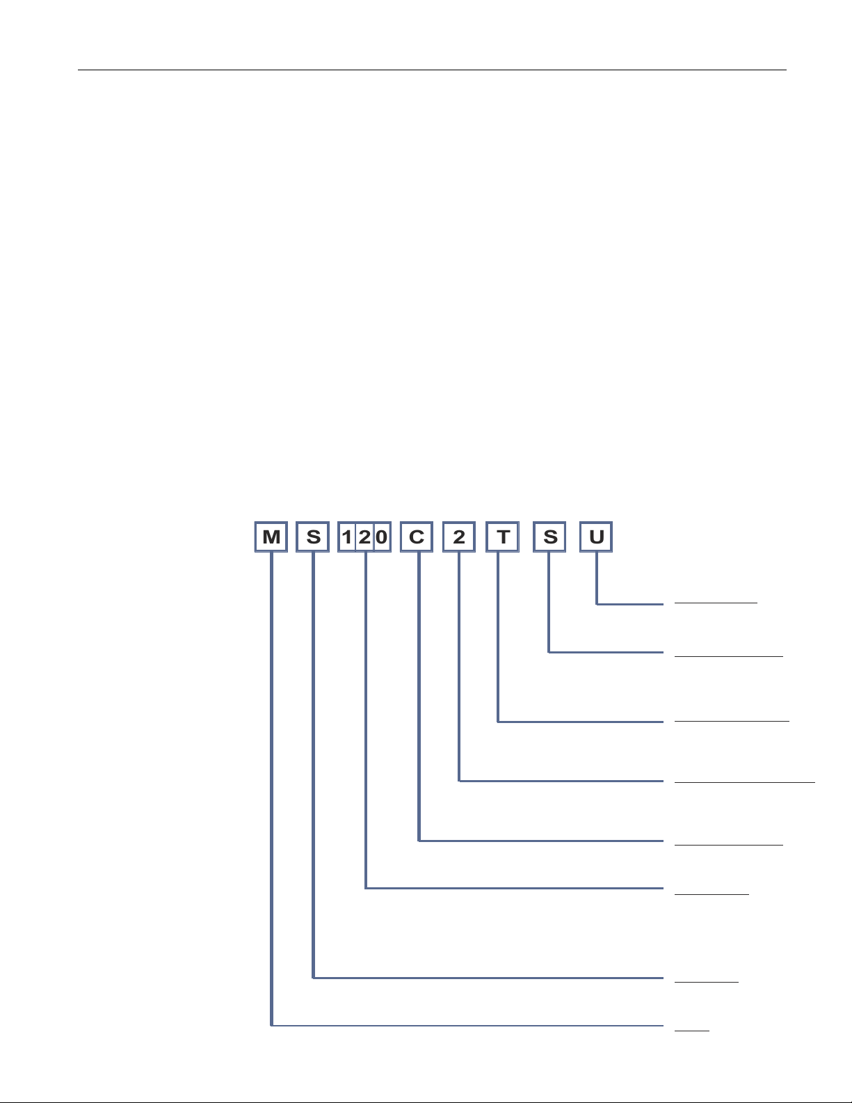
MODEL NUMBER
NOMENCLATURE
This Klimaire nomenclature supercedes
all previously issued (05/23/2013)
M
S
1 2
0
C
2
S T
U
Test Calification
U : UL/ETL
C : CSA
O : NLA
Casing Type & Color
B: Injection Molding – Black
S: Injection Molding – Silver
W:Injection Molding – White
M:Metal Casing – Silver
Minor Design Change
P : Plate Heater Exchanger
T : Tubular Stainless
Steel Heat Exchanger
Power Supply Code (V/ph)
1 – 120 / 1
2 – 240 / 1
5 – 240 / 3
Temperature Control
C : Automatic Constant
P : Power Level
Capacity (kW)
120 – 12.0
150 – 15.0
180 – 18.0
210 – 21.0
240 – 24.4
270 – 21.0
Heater Type
S : Tankless
H : Holding Tank
Brand:
M: Maxwell
1
Page 3
Congratulations! Now that you have purchased brand new Maxwell tankless water heater Aquafinity™ series and
will soon begin to enjoy the instant hot water supply as long as you need.
PRODUCT ADVANTAGES
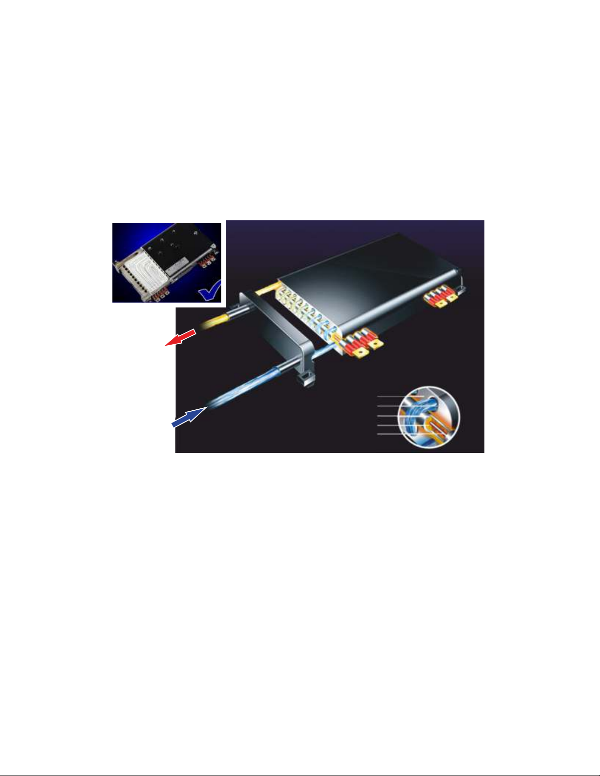
Your Maxwell heating appliance is an endless hot water on demand supply source. The heating chamber is made from
a single piece of cast aluminum with stainless steel water channels to have a longer and reliable life expectancy
despite the quality of the water entering the heater. The design of the enclosed nickel-chromium heating elements with
magnesium powder thermal conductivity insulation sets apart this heater.
Sheathed
Heating Plate
Hot Water
Cold Water
PRODUCT FEATURES
1. Energy efficient – Instantaneous heating on demand. Maxwell modern light weight and sleek
design compact tankless water heater does not require pre-heating and there are not standby heating losses.
2. Reliable and safe – water is completely separated from electricity by multi-layers of composite
nano insulation material.
3. Advance micro-processor control – self-diagnostic function automatically monitors and
displays working conditions with soft-start function providing constant temperature water flow
by engaging heating elements in stages for a precise temperature control for maximum
comfort.
4. Multi-protection devices – your heater has built-in protection features to prevent antiscalding, over-pressure, over-temperature and electricity isolation.
Aluminium magnesium cast body
Stainless steel water channel
Stainles steel
Magnesium powder thermal conductivity insulation
Nickel-chromium heating element
Picture 1
5. Convenience – LED wide screen touch button displays the working conditions, outlet
temperature, working time, and power consumption.
2
Page 4
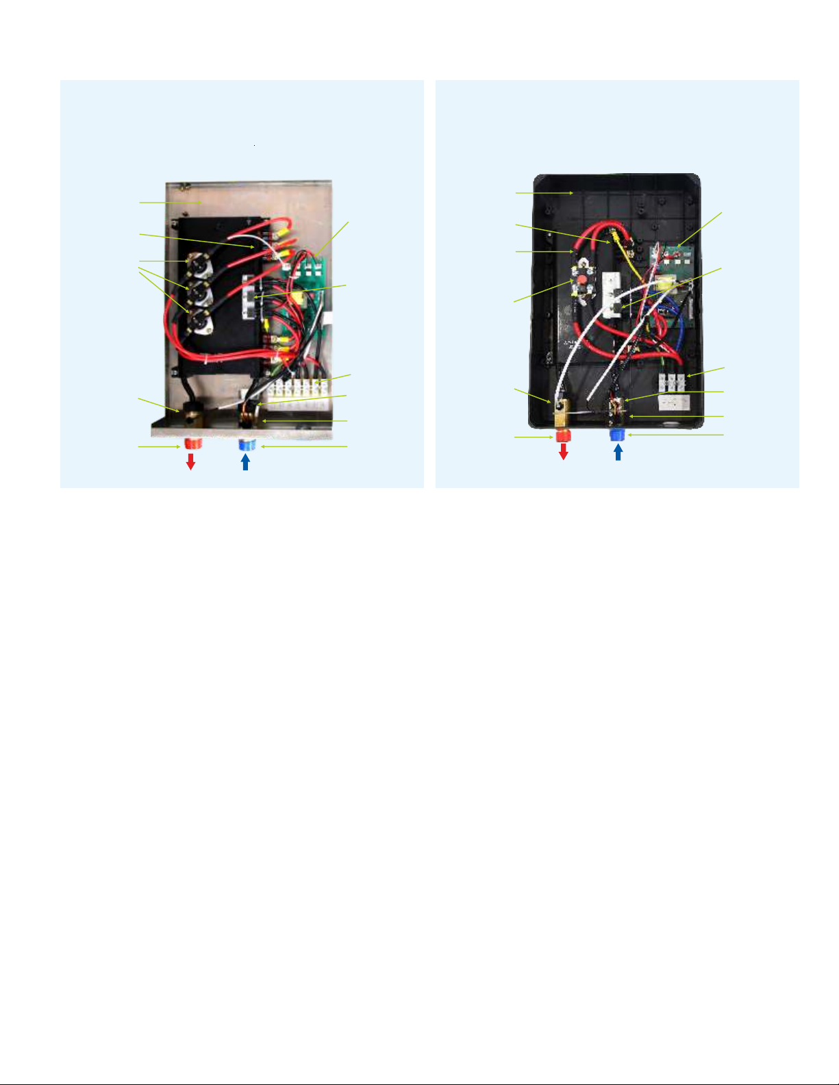
MS-C2TMU
Stainless Steel Model
MS-C2T_U
Injected Mold Model
Stainless Steel
Rear Cover
Temp. Controller
Thermal cut-out
(Manual Reset)
Temp. Sensor
Water Outlet
Connection
Control Board
Triac
Terminal Block
Flowmeter
Temp. Sensor
Water Inlet
Connection
Rear Cover
Heating Chamber
Thermal cut-out
(Manual Reset)
Temp. Sensor
Water Outlet
Connection
Control Board
Triac
Terminal Block
Flowmeter
Temp. Sensor
Water Inlet
Connection
Picture 2 Picture 3
1. WARNINGS
This is not a do-it-yourself project. Failure to have this appliance installed by a licensed and certified electrician and
plumber will void all warranties.
Under no circumstances should you attempt to clean, install, inspect, repair, disassemble or service the Maxwell electric
tankless water heater without first shutting off all power to the unit directly at the circuit breaker box. SERIOUS BODILY
INJURY OR DEATH COUILD OCCUR IF THIS WARNING IS IGNORED.
INSTALLATION OF THIS PRODUCT IS RESTRICTED TO INDOOR LOCATIONS BY QUALIFIED PLUMBING,
HEATING, MECHANICAL, ELECTRICAL CONTRACTORS ONLY, IN ACCORDANCE WITH ALL NATIONAL,
STATE, PROVINCIAL, AND LOCAL ELECTRICAL AND PLUMBING CODES.
By installing this product you acknowledge the terms of manufacturer's warranty and your authorized dealers return
policy. Water heaters that have been installed cannot be returned. If you plan to install your water heater on a second
floor/above ground or in a heated attic space you must follow all code requirements for installation in your area. It is
highly recommended to install a drip pan connected to a safe drain as per code requirements below the water heater
to avoid property damage in case of eventual leaks, and / or install an active water leak detector and shut off valve to
turn off your water supply in the event that a leak is ever detected.
Installation of this product is restricted to indoor locations only.
2. ABOUT YOUR ELECTRIC TANKLESS WATER HEATER
Please read thoroughly and understand this safety and installation manual completely before beginning to enjoy your
new on demand electric Maxwell tankless water heater, as it contains important safety information and installation
instructions.
If you need assistance or have any questions please contact us at: (305) 593-8358
Please keep this manual for future reference and technical information.
3
Page 5

3. BEFORE YOU INSTALL YOUR TANKLESS WATER HEATER
By installing this product you acknowledge the terms of manufacturer's warranty and your authorized dealers
return policy. Water heaters that have been installed cannot be returned. If you have any questions regarding
the warranty or product return policies please consult your authorized dealer.
Please open your tankless water heater box and carefully unpacked it, and inspect all components.
4. SELECTING INSTALLATION LOCATION
Your tankless water heater is a compact design and it has to be wall mounted, however improper installation,
maintenance or service adjustments may cause property damage. This appliance is designed to be installed
vertically and indoors only. You may be able to install your appliance in outdoor location provided that it is
mounted in a suitable enclosure that protects it from rain and water splashing, direct sun light, debris, and
insects. This product should NOT be installed in locations where it may be subject to freezing temperatures. If
the water inside your tankless water heater unit freezes, it can cause severe and permanent damage that is not
covered under your warranty. If you suspect your Maxwell tankless water heater has frozen, do not turn on
your unit until it has completely thawed out, and you have inspected the unit for leaks.
It is recommended and you should give consideration to your existing plumbing configuration and location of
your main electrical panel, and future servicing. DO NOT locate the unit in a location that will be difficult to
access. Most of the times, it is better and easier to install your new appliance at the same location as your old
one.
Combustible materials should be kept at least 24 inches or 60 cm. from your unit and the output hot water pipe.
Your unit does not require any type of venting. You should avoid installing your unit in places subject to
excessive humidity, moisture or dust, and even splashing water or other liquids, like under water pipes, water
gutters, air conditioning drain or refrigerant lines that might leak or condense moisture that could drip onto the
unit. DO NOT install your unit above electrical boxes or junction boxes.
5. MOUNTING YOUR ELECTRIC TANKLESS WATER HEATER
Your appliance should be mounted on a solid and secure surface. Prior to installation ensure that the unit is
leveled before tightening the screws. We recommend that for ease of installation and service product should be
installed in upright position with the inlet and outlet water connections at the bottom of the unit.
Recommended clearances: Above and below unit 12” and front panel 6”.
CAUTION: Clearances to combustible materials should be at a minimum of 24” away from the unit, and the
water inlet and outlet connections.
4
Page 6
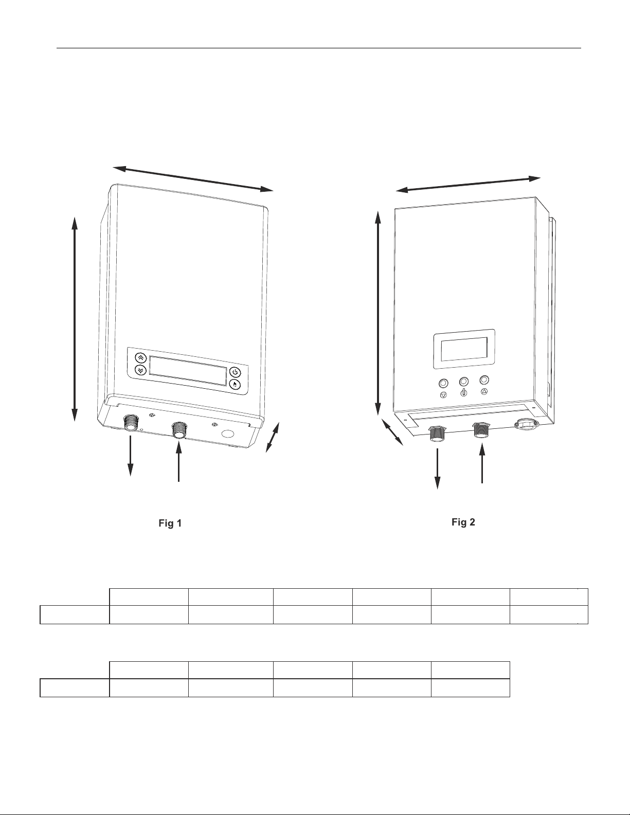
DIMENSIONS
B
MS-C2T_U
A
MS-C2TMU
D
E
WATER OUTLET
A x B x C
C
WATER INLET
Injected Mold Model Stainless Steel Model
MS120C2T_U
in. 15.1x10.2x3.7 15.1x10.2x3.7 15.1x10.2x3.7 15.1x10.2x3.7 15.1x10.2x3.7 15.1x10.2x3.7
MS150C2TMU
in.D x E x F
16.1 x 11 x 3.5 16.1 x 11 x 3.5 16.1 x 11 x 3.5 16.1 x 11 x 3.5 16.1 x 11 x 3.5
MS150C2T_U
MS180C2TMU
MS180C2T_U
MS210C2TMU MS240C2TMU
F
WATER OUTLET
MS210C2T_U MS240C2T_U
WATER INLET
MS270C2TMU
MS270C2T_U
5
Page 7

Installation Guideline
MS-C2T_U MS-C2TMU
Injected Mold Model
Stainless Steel Model
Front and back of the appliance(Typical)
Fig 4
Remove screw which fixes the bracket on back of the appilance (Typical).
Fig 5
Remove the bracket from the appilance (Typical).
6
Page 8

100 mm
3”-15/16
100 mm
3”-15/16
100 mm
3”-15/16
Hold the back bracket hanger in position against the wall and mark the three mounting holes. Drill holes of
Fig 6
¼” inch (6.00mm) diameter; the distance between every two holes is 3”-15/16 (100mm). Insert plastic anchoring
in the hole, place the bracket on the wall and secure the hanger using the screws supplied or an appropiate
alternative method.
100 mm
3”-15/16
Fig 7
Remove (4) screws on appliance to remove the front cover. Carefully lift the cover a few inches of the unit.
Disengage the LCD panel plug connecting the front cover to the body of the unit. Remove the cover completely.
Warning: If LCD connection cable cannot be disengaged, simply set the front cover aside and keep
the cable connected.
7
Page 9

E L1 L2 L1 L2 L1 L2
Typical view (model MS210C2TMU)
Fig 8
Fix the appilance to the bracket which was screwed to the wall.
Make sure the unit is properly secured to the bracket.
6. PLUMBING AND MECHANICAL INSTALLATION
Please read these instructions truly and completely before installing your water heater.
Please follow all plumbing instructions carefully. This appliance must be installed by a licensed and qualified
plumber in accordance with all applicable national, state, provincial, and local plumbing codes. Failure to do so
could result in property damage and/or personal injury and void your warranty.
1. DO NOT SOLDER ANY PIPES WITH THE APPLIANCE CONNECTED TO. IF YOU DO, YOU COULD
DAMAGE THE FLOW SENSOR AND VOID THE WARRANTY.
2. A pressure valve and air purging fitting must be installed as shown in the cold water supply pipe, if the
pressure exceeds 150 psi (1 Mpa). Any threaded fittings should be installed using Teflon tape, or approved
liquid sealants, as code practices allow. The relief valve must be installed in accordance with applicable
codes. Use standard hydronic practices to eliminate air from the system.
3. Install air vent valves, expansion tanks, flow control valves, isolation valves, etc. as per code requirements.
4. The unit is designed to operate only when flow sensor senses water flow through it. Prior to powering up
(turning on your unit), PURGE ALL AIR FROM YOUR SYSTEM (see item 10 below), failure to do so might
cause an air-lock in your unit drying out the heat exchanger of your unit and cause permanent damage to the
heating element.
5. The unit should be connected directly to the water supply and it is extremely important to FLUSH the pipe
with water to remove any debris, or loose particles.
6. Check all the pipe connections and fittings for any leaks, and take corrective actions before proceeding.
7. Models MS120C2T_U require ½” NPT water connections.
8. Models MS150C2T_U, MS180C2T_U, MS210C2T_U, MS240C2T_U, MS270C2T_U require ¾” NPT water
connections.
9. Connect the cold water supply to the INLET threaded pipe, and the hot water to the OUTLET threaded pipe.
Important: A RUBBER WASHER MUST BE USED FOR PROPER SEAL.
8
Page 10

AFTER TIGHTENING BOTH FITTINGS AT THE WATER HEATER, PRIOR TO TURNING ON THE
10.
POWER OF THE WATER HEATER, OPEN SEVERAL HOT WATER FAUCETS AND ALLOW WATER
TO RUN THROUGH THE WATER HEATER FOR A MINIMUM OF 3 MINUTES. This process purges all
air from the water lines and the heater.
Fig 9
Connect the cable to the terminal blocks, please notice the guidance logo below the terminal blocks.
The unit will be connected to circuit breakers as per table 1
Average Water Consumpion
Application
Typical Shower
Typical Bath Tub Faucet
Bathroom Vanity Sink Faucet
Kitchen Sink Faucet
Clothes Washer
Heater Sizing Guide
Summer Winter
Inlet Water
Model Nº
Temp.
MS120C2T_U
MS150C2T_U
77º F 72º F 67º F 62º F 57º F 52º F 47º F 42º F 37º F
2.9 gpm 2.6 gpm 2.4 gpm 2.3 gpm 2.0 gpm 1.8 gpm 1.5 gpm 1.3 gpm 1.2 gpm
3.8 gpm 3.4 gpm 2.9 gpm 2.8 gpm 2.6 gpm 2.2 gpm 1.9 gpm 1.8 gpm 1.4 gpm
Flow Rate in
GPM at 60 PSI
1.5 to 2.0 GPM
2.0 to 3.0 GPM
0.5 to 1.5 GPM
1.0 to 2.2 GPM
1.5 to 3.0 GPM
Table 1
MS180C2T_U
MS210C2T_U
MS240C2T_U
MS270C2T_U
Shower (1.5 gpm) ― Sink Faucet (1.0 gpm) - All data above are based on water leaving temperature 105º F (40º C). 1.5 gpm showerhead flow rate;
1.0 gpm sink faucet flow rate, and adequate water pressure @ 60 psi. Actual performance may be altered by variations from these parameters.
For voltages less than 240 V the heating capacities will vary and it would be necessary to consider a higher capacity model.
4.3 gpm 3.9 gpm 3.4 gpm 3.3 gpm 2.9 gpm 2.8 gpm 2.6 gpm 2.3 gpm 2.0 gpm
5.4 gpm 4.8 gpm 4.1 gpm 3.8 gpm 3.5 gpm 3.0 gpm 2.8gpm 2.5 gpm 2.4 gpm
6.0 gpm 5.2 gpm 4.5 gpm 3.8 gpm 3.7 gpm 3.2 gpm 3.0 gpm 2.7 gpm 2.5 gpm
6.8 gpm 5.7 gpm 5.1 gpm 4.4 gpm 3.9 gpm 3.6 gpm 3.3 gpm 3.0 gpm 2.7 gpm
9
Page 11

Temperature Rise
o
F
Table 2
Model
Power
(kw)
Water
Flow(GPM)
MS120C2T MS150C2T MS180C2T MS210C2T MS240C2T MS270C2T
12 15 18 21 24
0,5 164 205 246 287 328 369
1,0 82 102 123 143 164 184
1,5 55 68 82 96 109 123
2,0 41 51 61 72 82 92
2,5 33 41 49 57 66 74
3,0 27 34 41 48 55 61
3,5 23 29 35 41 47 53
4,0 20 26 31 36 41 46
4,5 18 23 27 32 36 41
5,0 16 20 25 29 33 37
5,5 15 19 22 26 30 34
6,0 14 17 20 24 27 31
6,5 13 16 19 22 25 28
7,0 12 15 18 20 23 26
27
Temperature Rise
Temp Rise
120
110
100
90
80
70
60
50
40
30
20
10
0
Based upon DOE formula for calculating flow at rise
o
F
1 2 3 4 5 6
0,5 1,0 1,5 2,0 2,5 3,0 3,5 4,0 4,5 5,0 5,5 6,0 6,5 7,0
o
F @ 240V vs. Flow Rate (GPM)
Flow Rate (gpm) =
Temp rise (ºF)
10
1
MS120C2T
2
MS150C2T
3
MS180C2T
4
MS210C2T
5
MS240C2T
6
MS270C2T
Flow Rate
GPM
kW rating x 6.83
Diagram 1
Page 12

7. ELECTRICAL INSTALLATION
Please follow all electrical instructions carefully. This appliance must be installed by a licensed and
qualified electrician in accordance with all applicable national, state, provincial, and local electrical codes.
All wiring (wire gages), circuit breakers (protector), must comply with the US National Electrical Code
(NEC), in the USA, or the Canadian Electrical Code (CEC). Failure to do so could result in property
damage and/or personal injury and void your warranty.
The Canadian electrical code generally requires all wires and corresponding circuit breakers used to install
tankless water heaters shall be sized to a minimum of 125% of the maximum current rating of the water
heater. (See model specifications and details below).
Before installing this appliance make sure the house has sufficient electrical power available to handle the
maximum amperage load of the applicable model of your heater.
Required Breaker Size to be installed in the main electrical panel
Table 3
Model No. MS120 MS150 MS 180 MS210 MS240 MS270
Breakers for
Main
Elecrical
Panel
Without the
Sub-panel
Amperage requirementes are based on 240 v
Check your local electrical code requirements for different voltage applications
Qty. 1
Double
Pole
60 A
Qty. 2
Double
Pole
50 A
Qty. 2
Double
Pole
50 A
Qty. 3
Double
Pole
40 A
Qty. 3
Double
Pole
40 A
Qty. 3
Double
Pole
50 A
A. Make sure all power sources to the unit are disconnected before doing any connection to the terminal box
and working with it. Follow the wiring diagrams based on the unit you have purchased. All mounting and
plumbing installation must be completed before proceeding with the electrical installation.
B-1. MS120C2T_U must be connected to a single double pole breaker. Read all name plates carefully and wire as
per instructions, and table 1.
11
Page 13

MODEL MS120C2T_U
Wiring Diagram
L1
L2
THERMAL CUT-OUT 194º F
E
CONTROL
SYSTEM
R1
T1
R2
T2
REMARK: J:RELAY R:HEATING SYSTEM T:TRIAC
10.2 in
11.22 in
DOWN
Fig 11
UP
Display screen
ON/OFF
Heating chamber
OUTLET TEMP.SENSOR
Bottom case
DISPLAY
SCREEN
INLET TEMP.SENSOR
FLOWMETER
Fig 10
Temp. sensor
WIRE CONNECTIONS TO BREAKERS
E / G L1 L2
Double Pole Breaker
60 A MS120
12
E L1 L2
Flowmeter
Control board
Display screen
Terminal blocks
Page 14

MS150C2T_U
MS180C2T_U
Wiring Diagram
L1
L2
L1'
L2'
E
THERMAL CUT-OUT 194º F
CONTROL
SYSTEM
R1
T1
R2
T2
OUTLET TEMP.SENSOR
DISPLAY
SCREEN
REMARK: J:RELAY R:HEATING SYSTEM T:TRIAC
B-2. MS150C2T_U & MS180C2T_U must be connected to two double pole breaker.
Read all name plates carefully and wire as per instructions, and tables 2 and 3.
11 in
MS150C2T_U MS180C2T_U
Heating chamber
16.14 in
Display screen
UP
ON/OFF
DOWN
INLET TEMP.SENSOR
FLOWMETER
Fig 12
Bottom case
Control board
Display screen
Fig 13
WIRE CONNECTIONS TO BREAKERS
E / G L1 L2 L1 L2
Double Pole Breaker
40 A MS150
50 A MS180
Double Pole Breaker
40 A MS150
50 A MS180
Temp.sensor
13
E L1 L2 L1 L2
Flowmeter
Terminal blocks
Page 15

MS210C2T_U
MS240C2T_U
THERMAL CUT-OUT 194º F
MS270C2T_U
Wiring Diagram
L1
L2
L1'
L2'
L1"
CONTROL
SYSTEM
T1
T2
T3
L2"
E
OUTLET TEMP.SENSOR
REMARK: J:RELAY R:HEATING SYSTEM T:TRIAC
B-3. MS210C2T_U, MS240C2T_U, & MS270C2T_U must be connected to two double pole breaker.
Read all name plates carefully and wire as per instructions, and tables 2 and 3.
DISPLAY
SCREEN
INLET TEMP.SENSOR
FLOWMETER
MS210C2T_U MS240C2T_U MS270C2T_U
11 in
Bottom case
R1
R2
R3
Fig 14
16.14 in
Display screen
UP
ON/OFF
DOWN
Fig 15
Temp.sensor
WIRE CONNECTIONS TO BREAKERS
E / G L1 L2 L1 L2 L1 L2
Double Pole Breaker
40 A MS210
40 A MS240
50 A MS270
Double Pole Breaker
40 A MS210
40 A MS240
50 A MS270
Heating chamber
Double Pole Breaker
40 A MS210
40 A MS240
50 A MS270
E L1 L2 L1 L2 L1 L2
Flowmeter
Control board
Display screen
Terminal blocks
14
Page 16

C. Using the required wire gage as per table 3 that meets all applicable electrical codes for the size of the
required breakers, run a ground wire and two pair of wires per breaker from the main breaker panel to the
tankless water heater unit. Refer to the corresponding wire connections to breakers chart above.
D. The ground wire must be connected to "ground" at the circuit breaker panel.
E. Double check the electrical connections to make sure they are correct and all the wire connections are tight
and secure, and the unit has been connected to a ground in accordance with applicable codes.
Injected Mold Model
Phase
Voltage V
Wattage kW
Max. Amp. Load @ 240V A
No. of circuits n
Min. required double pole
circuit breaker
Min. wire size AWG cooper
Min. water flow to activate
Working pressure PSI/bar
Weight
Model
A
kg
Product Dimensions mm
Water connections NPT
Stainless Steel Model
Model MS150C2TMU MS180C2TMU MS210C2TMU MS240C2TMU MS270C2TMU
Phase
Voltage V
Wattage kW
Max. amp. load A
No. of circuits
Min. required circuit breaker
Min. wire size AWG cooper
Min. water flow to activate
Working pressure PSI/bar
Weight lb
Product Dimensions in
Water connections NPT
GPM / L/min.
@ 240V
GPM / L/min.
MS120C2T_U MS150C2T_U MS180C2T_U MS210C2T_U MS240C2T_U MS270C2T_U
lb
385x260x93
in.
15.1x10.2x3.7
A
16.1 x 11 x 3.5
1
240
12
50
1
60
8
0.84 / 3.2
3.6
7.9
1/2” 3/4” 3/4” 3/4” 3/4” 3/4”
1 1 1 1 1
240 V
15kw
63
2 2 3 3 3
2 X 40
2 X 8
0.84/ 3.2
17.6
3/4”
1
240
15
63
2
2 x 40
2 x 8
0.84 / 3.2
385x260x93
15.1x10.2x3.7
5.3
11.7
385x260x93
15.1x10.2x3.7
240V
18kw
75
2 X 50
2 X 8
0.84/ 3.2
17.6 17.6 17.6 17.6
16.1 x 11 x 3.5 16.1 x 11 x 3.5 16.1 x 11 x 3.5 16.1 x 11 x 3.5
3/4”
1
240
18
75
2
Max.150/10
5.3
11.7
3 x 40
0.84 / 3.2
385x260x93
15.1x10.2x3.7
2 x 50
2 x 8
0.84 / 3.2
240 V 240 V 240 V
21kw
88
3X 40
3 X 8
0.84/ 3.2
Max.150/10
3/4”
1
240
21
88
3
3 x 8
5.5
12.1
24kw
3X 40
3 X 8
0.84/ 3.2
0.84 / 3.2
385x260x93
15.1x10.2x3.7
100
3/4”
1
240
24
100
3
3 x 40
3 x 8
5.5
12.1
3X 50
0.84/ 3.2
27kw
113
3 X 8
3/4”
Table 4
1
240
27
113
3
3 x 50
3 x 8
0.84 / 3.2
5.5
12.1
385x260x93
15.1x10.2x3.7
Table 5
Check your local electrical code requirements for different voltage application
15
Page 17

8. STARTING YOUR ELECTRIC TANKLESS WATER HEATER
Make sure to flush and clean the pipes prior to connect the pipes to the tankless water heater. Refer to section 6,
Plumbing and Mechanical Installation. Your heater must be cleaned, flushed, and purged. Any debris and foreign
material circulating through the system could cause harm to your tankless water heater and may lead to malfunction of
your appliance.
ALL AIR MUST BE REMOVED FROM THE SYSTEM AND YOUR ELECTRIC WATER HEATER BEFORE THE
ELECTRIC POWER IS ON.
When maintenance, repair, installation or disassembling is to be performed you must disconnect all power to the unit
directly at the breaker box. FAILURE TO DO SO CAN CAUSE SERIOUS BODILY INJURY OR DEATH.
9. OPERATION INSTRUCTIONS
1. Open water faucets for a few minutes until water flow is continuous and all air is purged from water pipes.
The unit must be operated after the breakers are turned on.
2. Check for and correct any leaking connections.
3. Turn on the circuit breaker to bring electrical power to the unit.
4. Press ON/OFF bottom to start up the unit.
If there is power to the unit, but no digital display, turn on the circuit breaker. Double check the cable to the
LCD panel on the front cover is connected tightly inside the unit, then turn the breaker back on.
After the unit is supplied with power, a beep sound can be heard and LED lights for 2 seconds, no other
display, the appliance keeps standby.
5. Press “ “ to turn ON/OFF the appliance. When the unit is ON, LED displays actual temperature
of the outlet water. After 5 seconds, the screen switches to the screen saver to conserve power.
The display screen light will be off. If you touch the screen it will light up again.
6. The outlet water temperature can be adjusted by changing the temperature settings on the control panel.
Press and to adjust the outlet temperature. Temperature setting range is 30--52°C/ 86-127℉.
WARNING: If the unit has been paused, you may initially get a short burst of very hot water from the unit.
Allow few seconds to run the water to cool down to the set point. Test the water before taking a shower.
If the unit will not be used in winter, drain out water completely so that the heater will not freeze.
Periodically clean inlet strainer and the shower head(s) to keep a free water flow.
7. Press to convert the temperature display between Fahrenheit degree and degree Celsius.
8. Your unit features an automatic memory function to avoid repetitive operation, when you turn on
the appliance, the default set temperature will be the same as previous setting.
Typical Installation
Fig 16
Wires from main service panel (3 circuit models typical)
BALL VALVE
WATER OUTLET
Note: *Check your local electrical code
requirements for different voltage applications
PRESSURE
RELIEF
VALVE
BREAKERS
FILTER
BALL VALVE
WATER INLET
16
Page 18

Trouble-shooting
Problems
1. Inlet and outlet fittings leaking A. Fittings not tight
B. Rubber washer worn-out
2. LED no signal
3. Functional keys not working
4. Water too hot
5. Water too cold
6. Outlet gets water smaller and
smaller.
7. LED displays E1
8. LED displays E3
9. Display overload
10. LED Displays E4
11. Pressure relief valve
releases water
7 and 8 should only be performed by a qualified electrician. The person who initially installed the unit is the best one to contact for help.
A. Power not connected.
B. LCD damaged.
A. No water out from shower.
B. Water pressure too low.
C. Key or PCB damaged.
A. Too high temperature set.
B. Water flow too small.
A. Low temperature set.
B. Water flow too much.
Inlet strainer or shower clogged.
Outlet temp. is over 67℃/153℉
Temperature sensor failure
Inlet water flow is too high Reduce the inlet water flow
Dry heating
A. Outlet blocked
B. Inlet pressure over 0.7 Mpa - 102 psi
Possible Causes
A. Tighten fittings.
B. Change rubber washer.
A. Connect power to the unit.
B. Change LCD.
A. Open valve to get water.
B. Open valve to get pressure.
C. Change key or PCB.
A. Set a lower temperature.
B. Open valve bigger.
A. Set a higher temperature.
B. Reduce water flow.
Clean strainer and shower.
A Reduce the temperature
B Turn up the water flow
Please contact with your local dealer
Shut off. Clean all outlets of any debris,
dirt, any particle or scale inside the pipe.
A. Clean shower set
B. Reduce water pressure
Corrective Actions
Normal Maintenance
Note: Do not attempt to repair this water heater yourself. Call a service person for assistance. Always turn off of
these operations the power supply needs to be shut off.
It is not required any regular maintenance. However, to ensure consistent water flow, it is recommended following
maintenance.
1. Periodically remove scale and dirt that may build up at the aerator of the faucet or in the shower head.
2. There is a built in filter screen at inlet connection which should be cleaned from time to time. Please turn off the
water flow before doing this.
17
Page 19

305-593-8358
Customer Service
We are dedicated and proud of the top quality of the customer service provided by our support technicians.
Please feel free to contact us at 305-593-8358 for any questions you might have, and warranty service, or if
your certified installer needs assistance when installing a unit.
Your valuable suggestions and comments are always welcome, it will help us to continuously improve our
service as part of our commitment to serve you better.
customerservice@klimaire.com
www.klimaire.com
18
Page 20

Klimaire Products Inc.
2190 NW 89 Place Doral, FL 33172 - USA
Phone: 305 593 8358 Fax: 305 499 4378
Certified by
 Loading...