

Page 1
Models:
MASF036-N1, MASF048-N1, MASF060-N1
(2 Speed, with Micro-Switch)
MASF036-N1
MASF048-N1
MASF060-N1
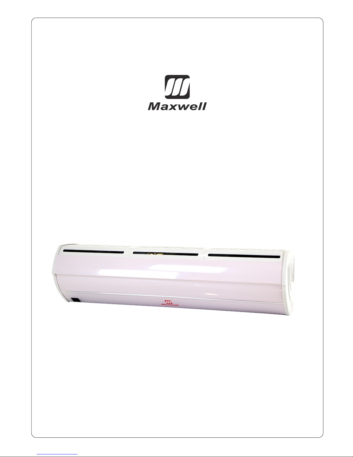
AIR CURTAIN
USER’S MANUAL
Maxwell
Page 2
Maxwell
1. Before plugging in power cord into power source, use a screw driver to rotate
fan blades with caution.
2. Ensure that fan blades rotate smoothly, if not remove the front cover screws to open
the front cover of air curtain.
3. Re-align the fan blade bearings with motor to fix this issue. Once again, rotate fan blade
to ensure it is rotating smoothly before screwing the front cover back to the air curtain.
4. Now you are ready to plug in 110V-120V power source; press and test both Hi and Lo speeds.
5. Now that all testing procedures have been cleared and met, refer to section 2 and commence
the installation.
FIRE, ELECTRICAL SHOCK HAZARD
Failure to follow this warning could result in personal
injury, death and/or property damage.
The ability to properly perform maintenance on this
equipment requires certain knowledge, mechanical skills,
tools, and equipment. If you do not possess these, do not
attempt to perform any maintenance on this equipment
other than those procedures recommended in the User's
Manual
STOP, READ, AND TEST BEFORE INSTALLATION
Page 3

Product Introduction
Identification & Installation Dimensions
Installation Planning and Cautions
Installation Instructions
Technical Parameters
2 Speed Switch Wiring Diagram
Wiring Diagram for Door Switch
Operation
Maintenance & Cleaning
Support & Contact Information
Contents
1.
2.
3.
4.
5.
6.
7.
8.
9.
10.
CAUTIONS
a) Use the unit at the rated voltage and frequency indicated on the nameplate.
b) Disconnect power source before unit operation.
c) Routing maintenance must be done every year.
d) Never use petrol, benzese, thinner or any other such chemical for cleaning the unit.
e) Do not allow water or any liquid to enter motor.
f ) When power supply comes from socket, the plug must accord with IEC335-1. When the
power cord is connected with charging line directly, all polarity switches that the contact gap is
3mm at least must be installed in the charging line.
Page 4

Create an invisible barrier over your door with Maxwell MASF series. Adopting the highest
technology in aerodynamics, all Maxwell Air Curtains run smoothly with low noise. MASF Series
Air Curtain by Maxwell boasts a streamlined modern appearance with no visible exterior screws.
Features stainless cover constructed of durable aluminum as attached mounting plate. They are
ideal for any location where you would like to create an invisible barrier to dust, insects, and
pollution. The powerful airflow divides the inside and outside environments into two independent
temperature zones. This minimizes air conditioned/heated air losses through opened doorways
and areas with doors that are constantly opening and closing. Easy to adjust with directional airflow louver and convenient two-speed hi-lo fan operation controlled by a unit surface mount
switch. The air curtain uses ambient air and is NOT an air conditioner.
Includes: 36” air curtain, door switch, installation hardware, 5 ft. power cord with grounded NEMA
5-15 plug, user's manual, installation manual, manufacturer warranty.
IDENTIFICATION & INSTALLATION DIMENSIONS
Units: in
MODEL A B C D E F G H I
MASF036-N1
35.4 27.4 --- --- 1.8 3.9 8.5 9.1 4.8
MASF048-N1
47.2 39 11.6 ---
MASF060-N1
59 50.6 19.8 ---
2
PRODUCT INTRODUCTION
1
Page 5

3.5 Don't allow gaps between the air curtain unit
and wall. Use aluminum wall bracket attached to
the back of the air curtain unit for a secure
installation.
3.6 Do not install the air curtain unit in a location
where it is exposed to water, excessive stream,
explosive gas, or corrosive gas.
To ensure durability.
INSTALLATION
A) Installing on A concrete wall:
4.1.1 Remove the attached mounting plate by
removing the fixed screws on the back of the main
body.
4.1.2 Determine the mounting location with the
mounting plate. Drill holes and insert a Zinc-Plated
Steel Hex-Nut Head Sleeve Anchor (not included).
4
INSTALLATION CAUTION
Must follow the following procedures when installing air curtain:
3.1 Please install air curtain in a sturdy and secure
place to avoid instability that can cause injury and
damage to your air curtain unit.
3.2 Please install the unit inside and not outdoors,
for best efficiency.
3.3 Install air curtain unit between 7 to 9 ft. from
the ground.
3.4 When the entrance is wider than the unit, it is
recommended to install two or more units in
parallel. In this case, provide 20-40mm gaps
between the units.
3
Page 6

C) Installing from the ceiling:
(Note: this installation is NOT recommended; the ceiling brackets are not supplied)
4.3.1 Remove the attached mounting plate by
removing the fixed screws on the back of the
main body.
4.3.2 Securely mount the ceiling brackets (not
included) see figure below.
4.3.3 Set mounting plate to the ceiling brackets
and tighten securely. The position of the mounting
plate can be adjusted in a vertical direction
according to the application needed.
Max distance 100 mm.
4.3.4 Do the same as step A to install the main body.
B Installing on a wooden wall: (Note: make sure the screws are secured in the wood, attach an
extra wood frame to the wall if needed for safety purposes.)
4.2.1 Remove the attached mounting plate by
removing the fixed screws on the back of the
main body to determine the precise mounting
location. Securely mount the mounting plate
to the wooden wall with tapping screws.
See figure below.
4.2.2 Hang the main body onto the upper end of the
mounting plate, and then tie the bottom fixing screws
back to the mounting plate.
4.1.3 Tighten the nuts to secure the mounting
plate to the wall after cement setting (use washers
and nuts) see figure.
4.1.4 Hang the main body onto the end of the
mounting plate, and then tighten the bottom fixing
screws back to the mounting plate.
Page 7

2 SPEED SWITCH WIRING DIAGRAM
GREY
BLACK
BLACK
BLACK
Hi
WHITE
GREEN
N
L
BLUE
BROWN
BLUE
THERMAL
CUT-OUT
BLUE
THERMAL
CUT-OUT
THERMAL
CUT-OUT
BLUE
K
OFF
Lo
RED
YELLOW
ORANGE
(YELLOW)
C
YELLOW
(YELLOW)
ORANGE
RED
C C
ORANGE
(YELLOW)
YELLOW
RED
6
D For above ceiling
4.4.1 Fix the air curtain as in the procedure for
installing on the concrete wall.
4.4.2 Then pipe as below Fig. Instructs.
TECHNICAL PARAMETER
MODEL
Volt.
(V~)
Freq
(Hz)
Max input
power
(W)
Max air
speed
(ft/s)
Air volume
(cfm)
Noise
(dB)
Net
weight
(LBS)
H L H L H L H L
MASF036-N1
110 60
230 200
52.5 42.7
647 530 52 49 28.7
MASF048-N1 290 260 883 707 53 50 34.2
MASF060-N1 380 350 1120 883 55 52 44
5
Page 8

COM – common
NO – normally open
NC – normally close
8.1: After connecting to power, (110v, 60Hz) press switch to either [L] for – Low Speed,
or [H] for – Hi Speed. Depending on location and application needed.
8.2: Depending on the location of installation, adjust the air louvers to about 10 to 15 degrees
to obtain optimum efficiency.
SUPPORT AND CONTACT
Optional door switch & weather proof cover
WIRING DIAGRAM FOR DOOR SWITCH 7
Save energy & eliminate unnecessary air circulation
8 OPERATION
9 MAINTENANCE & CLEANING
9.1. Use the unit at the rated voltage and frequency indicated on the rating label.
9.2. ALWAYS disconnect power source before unit installation or maintenance service.
9.3. Routine maintenance must be done every year.
9.4. Plastic parts should be cleaned with mild soap water, thoroughly remove soap film with a
clean damp cloth.
9.5. Wipe the exterior surfaces of the fan with a moistened cloth with a solution of mild detergent
and water.
9.6. Dry the case with a soft dry cloth before operating the unit
10
2190 NW 89TH Place Doral, FL 33172 USA
TEL: (305) 593-8358 FAX: (305) 499-4378
www.heatandcool.com sales@heatandcool.com
Page 9

Rockwell
Made by
Maxwell
2190 NW 89TH Place Doral, FL 33172 USA
TEL: (305) 593-8358 FAX: (305) 499-4378
www.heatandcool.com sales@heatandcool.com
 Loading...