

Page 1
User’s Manual
Benutzerhandbuch
Manuel d’Utilisation du Treuil
Manual del Usuario
Gebruikershandleiding
Manuale Utente
GB
DE
FR
ESP
NL
IT
www.maxwellmarine.com
Page 2
GB
• Please read this manual thoroughly before installation and using the capstan. Failure to adhere
to the correct procedures, recommendations and guidelines described in this Owner’s Manual
may invalidate the warranty.
• Correct selection of capstan together with correct installation, care in use and maintenance,
are essential for long life and reliable performance.
DE
• Bitte lesen Sie dieses Handbuch sorgfältig durch, bevor Sie die Ankerspill installieren
und benutzen. Falls die richtigen Vorgehenswesen, Empfehlungen und Richtlinien,
die im Benutzerhandbuch beschrieben sind, nicht befolgt werden, kann der
Garantieanspruch erlöschen.
• Eine richtige Auswahl an Ankerspill, gekoppelt mit einer richtigen Installation, sorgfältige
Benutzung und Instanderhaltung, sind erforderlich für eine lange Lebensdauer und
verlässliche Leistung.
FR
• Lisez ce manuel au complet avant d’entreprendre l’installation du cabestan. Le non-respect
des procédures, des recommandations et des lignes directrices correctes décrites dans ce
Manuel d’Utilisation peuvent annuler la garantie.
• La sélection correcte du cabestan avec l’installation correcte, les soins en usage et en
maintenance sont essentiels pour une durée longue de vie et un fonctionnement fiable.
ESP
• Por favor, antes de proceder a la instalación y utilizar el cabrestante lea la totalidad de este
manual. No seguir los procedimientos correctos, las recomendaciones y las pautas descritas
en este manual del propietario podría ser motivo para anular la garantía.
• La correcta elección e instalación del cabrestante, además de su uso y mantenimiento
adecuado, son fundamentales para la durabilidad y fiabilidad en la operación del mismo.
NL
• Lees voorafgaan aan de installatie en het gebruik van de kaapstander deze handleiding
grondig door. Het niet naleven van de juiste procedures, aanbevelingen en richtlijnen zoals
beschreven in deze handleiding, kan de garantie doen vervallen.
• De juiste selectie van kaapstander, samen met een juiste installatie en zorgvuldig gebruik en
onderhoud, zijn van essentieel belang voor een lange levensduur en een betrouwbare werking.
IT
• Leggere attentamente questo manuale prima di installare ed utilizzare il tonneggio. Il mancato
rispetto delle corrette procedure, consigli e linee guida descritti in questo Manuale Utente può
invalidare la garanzia.
• La corretta scelta del tonneggio, insieme ad una corretta installazione, attenzione nell’uso ed
alla manutenzione sono essenziali per una lunga durata e prestazioni ottimali.
INTRODUCTION / EINLEITUNG / INTRODUCTION / INTRODUCCIÓN
INLEIDING / INTRODUZIONE
IMPORTANT INFORMATION / WICHTIGE INFORMATIONEN / INFORMATIONS IMPORTANTES
INFORMACIÓN IMPORTANTE / BELANGRIJKE INFORMATIE / INFORMAZIONI IMPORTANTI
GB
• The capstan is ideal for handling mooring or docking lines, or retrieving a second anchor.
• Keep hands, feet, loose clothing and hair well clear of the capstan and rope during operation.
• DO NOT attempt to break free a fouled anchor with the capstan. Secure the line to a bollard
or cleat and use the boat's engine to break the anchor out.
• DO NOT use capstan to haul a person up a mast.
DE
• Die Winde ist ideal für das Hantieren von Vertäuungs- oder Anlegeseilen, oder für das Einholen
eines zweiten Ankers.
• Halten Sie Hände, Füße, lose Kleidungsstücke und Haare während des Betriebs von der
Winde entfernt.
• VERSUCHEN SIE NICHT, einen verschmutzten Anker mithilfe der Winde zu befreien.
Sichern Sie das Seil an einem Poller oder Stollen und verwenden Sie den Motor des Boots,
um den Anker zu lösen.
• VERWENDEN SIE NICHT die Winde, um eine Person am Mast hochzuhieven.
FR
• Le cabestan est idéal pour gérer l’amarrage ou l’accostage des lignes, ou pour récupérer une
seconde ancre.
• Les mains, les pieds, les vêtements amples et les cheveux bien éloignés du cabestan et des
cordages pendant le fonctionnement.
• NE tentez PAS de libérer une ancre engagée sur le cabestan. Sécurisez le cordage sur un
poteau d’amarrage ou sur un taquet et utilisez le moteur du bateau pour libérer l'ancre.
• N’utilisez PAS le cabestan pour remorquer une personne jusqu'à un mât.
ESP
• El molinete es ideal para amarrar o atracar o recuperar una segunda ancla.
• Mantenga las manos, los pies, la ropa suelta y el cabello a distancia segura del molinete y el
cabo durante la operación.
• NO trate de soltar un ancla atrapada usando la fuerza del molinete. Amarre la línea a un
amarradero o cornamusa y use el motor de la embarcación para liberar el ancla.
• NO usar el molinete para subir al mástil a una persona.
NL
• De kaapstander is ideaal voor gebruik met meertrossen voor aan- en afmeren, of het ophalen
van een tweede anker.
• Houd tijdens gebruik handen, voeten, loshangende kleding en haren ver uit de buurt van de
kaapstander en de kabel/ketting.
• Gebruik de kaapstander NIET om een onklaar anker los te trekken. Bevestig de lijn aan een
bolder of kikker en gebruik de motor van de boot om het anker los te trekken.
• Gebruik de kaapstander NIET om iemand in de mast omhoog te trekken.
IT
• L’argano è ideale per gestire le operazioni di attracco e ormeggio, o per recuperare una
seconda ancora.
• Tenere mani, piedi, abiti ampi e capelli ben lontani dall’argano e dalla cima durante l’uso.
• NON tentare di liberare un’ancora impigliata utilizzando l’argano. Fissare la linea ad una bitta
o ad una tacchetta ed utilizzare il motore della barca per liberare l’ancora.
• NON utilizzare l’argano per issare una persona a bordo.
Page 3
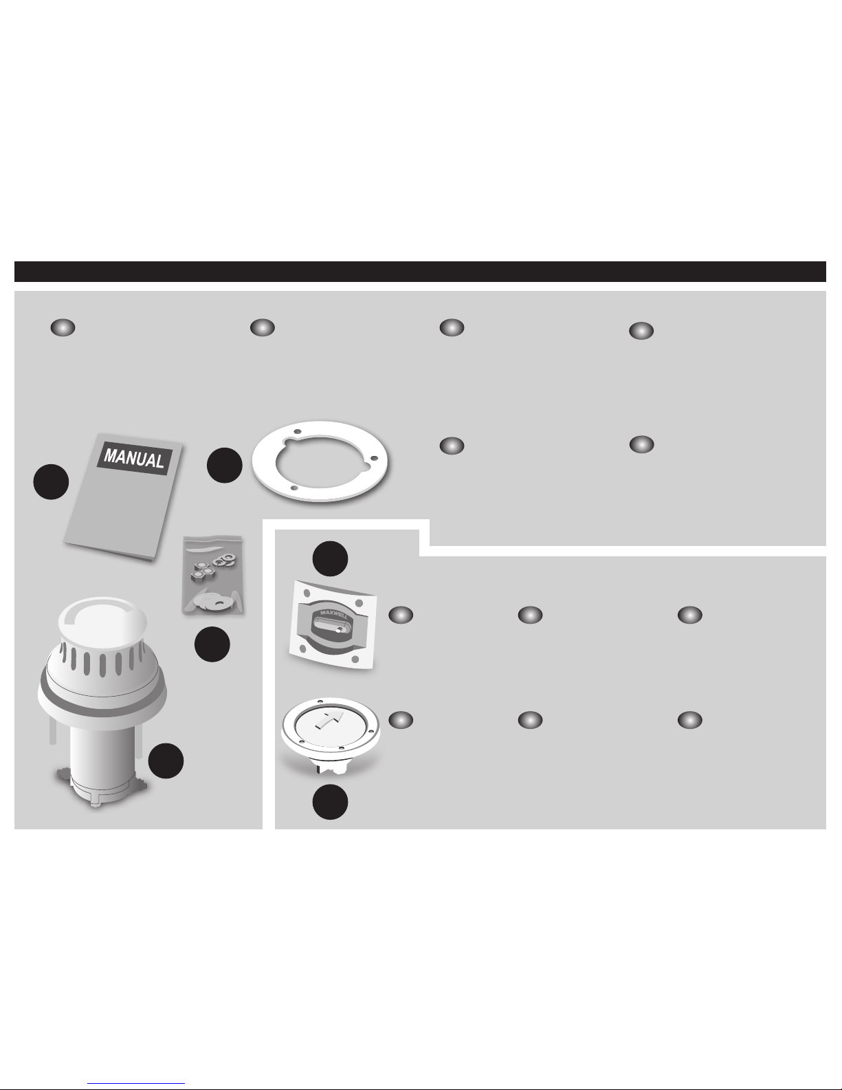
PACKING LIST/ VERPACKUNGSLISTE/LISTE D’EMBALLAGE/LISTA DE MATERIALES SUMINISTRADOS/PAKLIJST/CONTENUTO DELLA CONFEZIONE
Oltre a questo manuale
d'istruzioni i seguenti
elementi devono essere
forniti a corredo del salpa
ancora:
A. Guarnizione piana per
coperta
B. Dima di foratua coperta (in
fondo al manuale)
C. Minuteria (dadi, rondelle,
rondelle elastiche)
D. Tonneggio
IT
In addition to this
instruction manual, the
following components
should be included with
the windlass:
A. Deckplate Gasket
B. Deck Cutout Details (at rear
of manual)
C. Small Parts (nuts, washers,
spring washers)
D. Capstan
GB
Además de este manual de
instrucciones, deberían
incluirse los componentes
siguientes junto con
el molinete.
A. Junta de plancha de cubierta
B. Recorte con detalles de
cubierta (en la parte trasera del
manual)
C. Piezas Pequeñas (tuercas,
arandelas, arandelas de
muelle)
D. Cabrestante
ESP
Behalve deze
handleiding, horen
de volgende
onderdelen te worden
meegeleverd met
de ankerlier:
A. Dekplaatpakking
B. Dekuitsnijdingsdetails (achterin
de handleiding)
C. Kleine Onderdelen
(moeren, ringen, veerringen)
D. Le cabestan
NL
Zusätzlich zu dieser
Bedienungsanleitung,
werden die folgenden
Komponenten mit der
Ankerwinde geliefert:
A. Deckplattendichtung
B. Angaben für Deck-Ausschnitt
(hinten im Handbuch)
C. Kleinteile (schrauben,
unterlegscheiben,
federscheiben)
D. Ankerspill
DE
En outre de ce manuel
d’utilisation, les
composants suivants
devraient être inclus
avec le treuil :
A. Joint de la plaque du pont
B. Détails de l’encoche du
pont (à la fin du manuel)
C. Petites Pièces (écrous,
rondelles, rondelles
élastiques)
D. Tonneggio
FR
C
D
A
B
B
A
Les accessoires
suivantes peuvent
être exigées afin
d’achever l’installation:
A. Panneau du
Disjoncteur /de
l’Isolateur
B. Pédale de commande
Das folgende
Zubehör
könnte benötigt
werden, damit die
Montage
abgeschlossen
werden kann:
A. Sicherung /
Trennschalter
B. Fußschalter
The following
accessories may
be required to
complete your
installation:
A. Circuit Breaker
/isolator panel
B. Footswitch
FRDEGB
Para completar
la instalación
pueden
requerirse los
accesorios
siguientes:
A. Panel de disyuntor/
aislador
B. Interruptor de piso
ITESP NL
Vereist:
De volgende
accessoires zijn
mogelijk nodig om uw
installatie te voltooien:
A. Stroomonderbreker/
isolatorpaneel
B. Voetschakelaar
I seguenti
accessori
possono essere
necessari
per completare
l’installazione:
A. Pannello per interruttore
magnetotermico/
isolatore
B. Interruttore a pedale
Page 4
Serrer
Cela indique qu’il est important pour le fonctionnement et la maintenance du treuil qu’un quelcon-
que écrou / boulon est sufsamment serré.
Utiliser l’Outil
Ceci indique que l’utilisation d’un outil (qui n’a pas été fourni par Maxwell)
est exigée ici.
Correct
Ceci indique la méthode correcte pour achever
une tâche donnée.
Incorrect
Ceci indique la méthode incorrecte pour achever
une tâche donnée.
Apretar
Indica que apretar lo sucientemente una determinada tuerca/perno es importante para
la operación y mantenimiento del cabrestante.
Uso de herramienta
Indica que se requiere usar una herramienta
(No suministrada por Maxwell).
Correcto
Indica el método correcto de completar
una tarea determinada.
Incorrecto
Indica el método incorrecto de completar
una tarea determinada.
GB
SYMBOLS USED
Festziehen
Dies zeigt an, dass es wichtig für den Betrieb und die Wartung der Ankerwinde ist, das seine
bestimmte Mutter/Schraube hinreichend angezogen ist.
Werkzeug benutzen
Dies zeigt an, dass die Benutzung eines Werkzeugs (das nicht von Maxwell
mitgeliefert wurde) hier benötigt wird.
Richtig
Dies zeigt die angemessene Methode an, um eine bestimmte
Aufgabe zu erfüllen.
Falsch
Dies zeigt die falsche Methode an, um eine bestimmte Aufgabe zu erfüllen. Für eine Erklärung
hinsichtlich der in diesem Handbuch verwendeten Begriffe, schlagen Sie bitte im Glossar am Ende des
Handbuchs nach.
Tighten
This indicates that it is important to the operation and maintenance of the windlass that a given
nut/bolt is tightened sufciently.
Use Tool
This indicates that the use of a tool (which has not been supplied by Maxwell),
is required here.
Correct
This indicates the correct method of completing a given task.
Incorrect
This indicates the incorrect method of completing a given task.
Vastdraaien
Dit duidt erop dat het voor de werking en het onderhoud van de ankerlier belangrijk is dat een
bepaaldemoer/bout goed is vastgedraaid.
Gereedschap gebruiken
Dit duidt erop dat het gebruik van een stuk gereedschap (dat niet is bijgeleverd door Maxwell)
hier vereist is.
Juist
Dit duidt op de juiste methode van uitvoering van een
bepaalde taak.
Onjuist
Dit duidt op een onjuiste methode van
uitvoering van een bepaalde taak.
Stringere
Questo indica che è importante per l’uso e la manutenzione del salpa ancora che un
determinato dado/bullone sia ben stretto.
Usare attrezzi
Questo indica che è richiesto l’uso di un attrezzo (non fornito
da Maxwell).
Corretto
Questo indica il metodo corretto per svolgere una
determinata attività.
Scorretto
Questo indica il metodo scorretto per svolgere
una determinata attività.
DE
FR
ESP
NL
IT
BENUTZTE SYMBOLE
SYMBOLES UTILISÉS
SÍMBOLOS UTILIZADOS
GEBRUIKTE SYMBOLEN
SIMBOLI UTILIZZATI
Page 5

User’s Manual • Benutzerhandbuch • Manuel d’Utilisation du Treuil • Manual del Usuario • Gebruikershandleiding • Manuale Utente
1 2 3
A
D
B
C
Ø150mm (5 7/8”)
Ø100mm (4”)
Ø78mm (3 1/16”)
108mm (4 1/4”)
65mm (2 9/16”)
146mm (5 3/4”)
A1 B1
1
4
2
5
7
3
6
8
1 2 3
4 5
CAUTION
When operating capstan:
• Make sure that you do not operate the footswitch accidentally while putting
turns on the capstan.
• Keep your ngers, clothing and hair clear of the capstan.
IMPORTANT INFORMATION
• Start the main engine before operating the capstan.
• A circuit breaker / isolator should always be used with this capstan to protect
the motor and cables from overheating and damage.
• Always make sure the isolator switch is turned off when the system is not
being used.
• Extra turns around the drum will increase the grip and require less load on
the tail.
• Maxwell recommends clockwise rotation of the capstan.
TO HAUL IN USING THE CAPSTAN
1. Wind up to three turns of rope up the drum in the direction of pull.
2. Maintaining a light ‘tailing’ pull on the free end, start the capstan using the
foot switch.
3. As the capstan rotates, increase pull and ‘tail’ hand over hand to haul
the rope.
4. Reduce pull to slip the rope if required.
IMPORTANT INFORMATION
Plan location carefully:
1. Ensure the rode will feed correctly.
2. Ensure the deck is at. If not; install plinth to
ensure the capstan sits on a at surface.
3. Identify any bulkheads, wiring or piping under
the deck that should be avoided.
4. Ensure the mounting area is of appropriate
strength to accommodate loads applied by
capstan/anchor and rode.
ENGLISH
WIRING
INSTALLATION
SPECIFICATIONS
MAINTENANCE
After Use
1. Wash down topworks with
fresh water.
2. Check rope for wear and
wash down with fresh
water.
Every 3 Months
3. Clean capstan.
4. Check tightness of all
fasteners.
5. Apply a corrosion inhibitor
to the under deck
components.
Every Year
6. The motor should be
serviced by a qualied
technician.
7. Remove any rust build up
from the casing and paint
with a suitable coating.
SAFETY
• We recommend that connection of the power lines and control circuitry to the capstan be
done by qualied technicians, to ensure reliable and safe operation of the capstan.
• Installation must be carried out in accordance with relevant local electrical requirements
(USCG, ABYC, NMMA, CE).
• A circuit breaker/isolator is required.
• Position the circuit breaker/isolator (B) no further than 1.8 m (6 ft) away from the battery
(C) in an accessible and dry location. The winch circuit requires protection provided by an
isolator switch and either a fuse or circuit breaker.
FOOTSWITCH
• For safe operation, the Footswitch (D) should be approximately 500 mm (20”) from the
capstan (A).
• The below-deck part of the footswitch must be in a dry environment.
• The arrow on the footswitch should be arranged to indicate the direction of operation.
• Follow the instructions supplied with the footswitch, for steps on its installation.
MOTOR
• When tightening the cables to the motor, ensure the lower nut (A1) is secure against turning
when tightening the upper nut (B1). This will prevent damage occurring within the motor.
After all connections have been made, and the system has been tested, seal terminals against
moisture by spraying with a dry, corrosion preventative lm.
TIPS
• We recommend using crimp-on ring terminals and heat shrink tubing to connect
to terminals.
• We recommend the use of chafe protection on wiring when passing through bulkheads etc.
OPERATION
FITTING STEPS/INSTALLING STEPS
1. Use the Cut-Out Template, as a guide for
marking and cutting the holes.
2. Make sure the load is aligned with the
'To Load' arrow on Cut-Out Template.
3. Mark out the desired position for the holes.
4. Using hole saws and drill start drilling/cutting
holes in order from A to C (as marked on the
templates).
5. Seal the edges of the hole with epoxy to
avoid ingress of moisture. (Not required for
steel or aluminium.)
6. Use the gasket supplied to seal the capstan
to the deck. For boats of aluminium or steel
construction it is important the deckplate
assembly is insulated from the deck to
prevent electrolysis.
7. Align the deckplate with the holes cut into
deck and lower into place.
8. Fasten the deckplate to the deck using the
nuts and washers supplied. Tighten the nuts
progressively and evenly. Make sure the
installation is rm, but do not over tighten the
nuts. Do not use power tool.
Visit our website:
(www.maxwellmarine.com)
for a list of service centers
and agents.
GB
Power Supply (DC)
12V/24V
Motor Power
500W
Working Load
386kg
(850 lbs)
Haulage speed
(Dependant on the load)
24m/min
76ft/min
Net weight
5.5kg
(12lbs)
Circuit Breaker/Isolator
12V
80amp
24V
40amp
CABLE SIZE SELECTION
CABLE LENGTH
0-10m (0-33’) 10-20m (33’-65’)
mm² AWG mm² AWG
12V
16 6 25 4
24V
4 12 6 10
• Measure required length of electrical cable, use table below to select appropriate cable size.
• Cable length is total length from battery to winch then back again.
• Recommendations ensure less than 10% voltage drop at windlass motor when operating
under load.
• Recommendations based on copper conductors having an insulation thermal rating
of 90° C.
• Cables running through an engine area may need to be larger diameter
(refer to your installer).
• Use of cable diameters smaller than recommended will reduce windlass performance.
Larger cables can be used.
• Size of the recommended circuit breaker and ampacity of cable factored into calculations.
Note:
1. Before cutting deck, check all underdeck clearances. Read and understand installation instructions
contained within the manual.
2. Check your marked out dimensions carefully, before cutting and drilling. Deck bolt holes must be drilled
parallel and square to mounting faces.
3. VETUS-Maxwell is not responsible for any inaccurate data, due to reproduction errors of fax machines,
printers, photocopiers etc.
Page 6

User’s Manual • Benutzerhandbuch • Manuel d’Utilisation du Treuil • Manual del Usuario • Gebruikershandleiding • Manuale Utente
1 2 3
A
D
B
C
Ø150mm (5 7/8”)
Ø100mm (4”)
Ø78mm (3 1/16”)
108mm (4 1/4”)
65mm (2 9/16”)
146mm (5 3/4”)
A1 B1
1
4
2
5
7
3
6
8
1 2 3
4 5
ACHTUNG
Während der Bedienung des Ankerspills:
• Stellen Sie sicher, dass Sie nicht den Fußschalter ausversehen aktivieren,
während sich die Winde dreht.
• Halten Sie Ihre Finger, Kleidungsstücke und Haare von der Winde entfernt.
WICHTIGE INFORMATIONEN
• Starten Sie den Hauptmotor vor dem Betreiben der Winde.
• Ein Schutzschalter / Trennschalter sollte stets mit dieser Winde verwendet
werden, um den Motor und die Kabel vor Überhitzen und Schäden
zu schützen.
• Stellen Sie stets sicher, dass der Trennschalter ausgeschaltet ist, wenn das
System nicht in Gebrauch ist.
• Extra Drehungen um die Trommel erhöhen den Halt und verursachen eine
geringere Belastung für das Heck.
• Maxwell empehlt Drehung des Ankerspill.
DEN ANKERSPILL ZUM EINZIEHEN BENUTZEN
1. Winden Sie bis zu drei Umdrehungen an Seil auf der Trommel auf, in
Zugrichtung.
2. Während ein leicht ‚schleppender‘ Zug beibehalten wird, starten Sie die
Winde unter Verwendung des Fußschalters.
3. Während sich die Winde dreht, erhöhen Sie den Zug und ‘schleppen’ Sie
Hand über Hand (übergreifend), um das Seil zu ziehen.
4. Reduzieren Sie den Zug, um das Seil gleiten zu lassen, falls notwendig.
WICHTIGE INFORMATIONEN
Den Ort sorgfältig planen:
1. Vergewissern Sie sich, dass die Ankerleine/
Ankerspill richtig durchgeführt werden kann.
2. Vergewissern Sie sich, dass das Deck ach
ist. Falls nicht; installieren Sie eine Platform,
damit die Ankerspill auf einer achen
Oberäche sitzt.
3. Finden Sie jeden Schott, jede Verkabelung
oder Rohrleitung unter dem Deck, die
vermieden werden sollen.
4. Vergewissern Sie sich, dass der
Befestigungsort stark genug ist, um. Lasten
von Ankerspill /Anker und Ankerkette.
VERKABELUNG
INSTALLATION
SPEZIFIKATIONEN
INSTANDERHALTUNG
Folgenutzung
1. Waschen Sie den äußeren
Bereich mit frischem
Wasser.
2. Überprüfen Sie das Seil auf
Abnutzung und waschen
Sie es mit frischem
Wasser.
Alle 3 Monate
3. Sauber Ankerspill.
4. Überprüfen Sie
die Festigkeit aller
Befestigungsmittel.
5. Benutzen Sie einen
Korrosionsschutz auf allen
Komponenten unter Deck.
Jedes Jahr
6. Der Motor sollte von einem
qualizierten Techniker
gewartet werden.
7. Entfernen Sie jeglichen
Rost vom Gehäuse und
lackieren sie es mit einer
geeigneten Beschichtung.
SICHERHEIT
• Wir empfehlen Ihnen, dass die Verbindung der Stromkabel und Steuerschaltung an die
Ankerspill von qualizierten Technikern unternommen wird, damit eine verlässliche und
sichere Bedienung der Ankerspill garantiert werden kann.
• Die Installation muss gemäß den relevanten lokalen elektrischen Anforderung ausgeführt
werden (USCG, ABYC, NMMA, CE).
• Eine Sicherung/ein Trennschalter wird benötigt.
• Positionieren Sie die Sicherung/ den Trennschalter (B) nicht weiter als 1.8 m (6 ft) von der
Batterie (C) weg in einem zugänglichen und trockenen Ort. Die Schaltung der Winde muss
von einem Trennschalter und einer Sicherung geschützt werden.
FUßSCHALTER
• Für eine sichere Bedienung sollte der Fußschalter (D) ungefähr 500 mm (20”) von der
Ankerspill (A) entfernt sein.
• Der Teil des Fußschalters, der sich unter Deck bendet, muss in einer trockenen
Umgebung sein.
• Der Pfeil auf dem Fußschalter sollte so angeordnet sein, dass die Richtung der Bedienung
angezeigt wird.
MOTOR
• Wenn die Kabel am Motor befestigt werden, vergewissern Sie sich, dass die untere Mutter
(A1) festgedreht wurde, während die obere Mutter (B1) befestigt wird. Dies verhindert
potentiellen Schaden im Motor.
Nachdem alle Verbindungen gemacht wurden und das System getestet wurde, versiegeln Sie die
Klemmen gegen Feuchtigkeit, indem Sie sie mit einer trockenen, korrosionsschützenden
Schicht besprühen.
HINWEISE
• Wir empfehlen Klemmkabelschuhe und Warmschrumpfschläuche, um die Anschlüsse
zu verbinden.
• Wie empfehlen die Benutzung von Abriebschutz bei Kabeln, wenn sie durch
Schotten laufen.
BEDIENUNG
SCHRITTE ZUM ANBRINGEN / SCHRITTE
ZUR INSTALLATION
1. Benutzen Sie die Schablone, um zu wissen,
wo die Löcher markiert und gesägt werden
müssen.
2. Stellen Sie sicher, dass die Last mit dem‚
'To Load' auf der ausgeschnittenen
Schablone übereinstimmt.
3. Markieren Sie die gewünschten Positionen
für die Löcher.
4. Fangen Sie dann an mit Lochsägen und
Bohrer Löcher in der Reihenfolge von A bis
C zu bohren/sägen (wie es auf der Vorlage
markiert ist).
5. Dichten Sie den Rand des Lochs mit Epoxid
ab, um das Eindringen von Feuchtigkeit zu
vermeiden. (Nicht benötigt für Stahl oder
Aluminium.)
6. Benutzen Sie die Dichtung, die mitgeliefert
wurde, um die Ankerspill auf dem Deck
anzubringen und sie dort abzudichten. Für
Boote aus Aluminium oder Stahlkonstruktion
ist es wichtig, die Deckplatte Anordnung ist
aus dem Deck isoliert, um die Elektrolyse zu
verhindern.
7. Bringen Sie die Deckplatte und die Löcher,
die ins Deck gesägt wurden, in eine Linie,
und legen Sie die Platte auf ihre Position.
8. Bringen Sie die Deckplatte am Deck an,
indem sie die Muttern und Unterlegscheiben
benutzen, die mitgeliefert wurden. Befestigen
Sie die Schrauben stufenweise und
gleichmäßig. Vergewissern Sie sich, dass die
Installation befestigt ist, aber ziehen Sie die
Muttern nicht zu fest an. Benutzen Sie keine
Elektrowerkzeuge.
Besuchen Sie unsere Webseite:
(www.maxwellmarine.com)
für eine Liste von Servicecentern
und Vertretern.
DE
Netzteil (DC)
12V/24V
Motorleistung
500W
Ziehgeschwindigkeit unter
386kg
(850 lbs)
Arbeitslast
(Hängt von der Last ab)
24m/min
76ft/min
Reingewicht
5.5kg
(12lbs)
Sicherung/Trennschalter
12V
80amp
24V
40amp
• Messen Sie die gewünschte Länge der elektrischen Kabel, Verwendung Tabelle unten, um
die passende Kabelgröße auswählen.
• Die Kabellänge beträgt Gesamtlänge von Batterie bis Winde dann wieder zurück.
• Empfehlungen versichern weniger als 10% Spannungsfall beim Motor der Ankerwinde,
während sie unter Belastung läuft.
• Diese Empfehlungen sind darauf basiert, dass Kupferleiter eine Wärmegrenzleistung für die
Isolation von 90° C haben.
• Kabel, die durch einen Motorbereich laufen, könnten einen größeren Durchmesser benötigen
(den Installierer fragen).
• Wenn die Durchmesser der Kabel kleiner als empfohlen sind, wird die Leistung der
Ankerwinde reduziert. Größere Kabel können benutzt werden.
• Die Größe des empfohlenen Trennschalters und die Strombelastbarkeit des Kabels sind mit
einberechnet.
CABLE GRÖSSENAUSWAHL
KABELLÄNGE
0-10m (0-33’) 10-20m (33’-65’)
mm² AWG mm² AWG
12V
16 6 25 4
24V
4 12 6 10
Anmerkung:
1. Bevor Sie in das Deck sägen, überprüfen Sie den Freiraum unter dem Deck. Lesenund verstehen Sie die
Installationsanweisungen, die sich in diesem Handbuch benden.
2. Überprüfen Sie Ihre markierten Maße sorgfältig, bevor Sie sägen und bohren. Deck-Bolzenlöcher müssen
parallel und quadratisch zu den Montagestellen sein.
3. VETUS-Maxwell ist nicht verantwortlich für jegliche falsche Daten, die wegen Kopierfehlern von
Faxmaschinen, Druckern, Fotokopierern usw. entstanden sind.
DEUTSCH
Page 7

User’s Manual • Benutzerhandbuch • Manuel d’Utilisation du Treuil • Manual del Usuario • Gebruikershandleiding • Manuale Utente
1 2 3
A
D
B
C
Ø150mm (5 7/8”)
Ø100mm (4”)
Ø78mm (3 1/16”)
108mm (4 1/4”)
65mm (2 9/16”)
146mm (5 3/4”)
A1 B1
1
4
2
5
7
3
6
8
1 2 3
4 5
ATTENTION
Lors le fonctionnement du cabestan:
• Assurez-vous de ne pas utiliser accidentellement la commande à pédale tout
en plaçant tour à tour le cabestan.
• Gardez vos doigts, vos vêtements et les cheveux loin du cabestan.
INFORMATIONS IMPORTANTES
• Démarrez le moteur principal avant de faire fonctionner le cabestan.
• Un disjoncteur / isolateur devra être utilisé avec ce cabestan pour protéger
le moteur et les câbles de la surchauffe et des dommages.
• Assurez-vous toujours que le sectionneur est hors tension lorsque le
système n’est pas utilisé.
• Des tours supplémentaires autour du tambour augmenteront l'adhérence et
nécessiteront moins de charge sur la queue.
• Maxwell recommande rotation horaire du cabestan.
VIRER EN UTILISANT LE CABESTAN
1. Enroulez jusqu'à trois tours de câble sur le tambour en place dans
la direction de la traction.
2. Gardez un léger mou sur l'extrémité libre, démarrez le cabestan en utilisant
l'interrupteur à pédale.
3. Lors de la rotation du cabestan, augmentez la traction et tenez la queue
pour transporter la corde.
4. Réduisez la traction pour glisser la corde si nécessaire.
INFORMATIONS IMPORTANTES
Planier attentivement l’emplacement:
1. Assurer le fonctionnement correct (la corde).
2. Assurer que le pont est plat. Sinon ; installer
la plinthe pour s’assurer que le cabestan
s’assoit sur une surface plate.
3. Identier toute cloison, câblage ou tuyauterie
sous le pont qui devrait être évité.
4. Assurer que la zone d’installation est
sufsamment solide pour accommoder des
charges appliquées par le cabestan/l’ancre et
le rode.
CÂBLAGE
INSTALLATION
SPÉCIFICATIONS
MAINTENANCE
Après l’utilisation
1. Véries que l'embrayage
soit correctement ajusté.
Laver les mécanismes
supérieurs avec de l'eau
fraîche.
2. Vérier la corde pour l'usure
et laver-la avec de l'eau
fraîche.
Tous les 3 Mois
3. Propre le cabestan.
4. Vérier le serrage de
toutes les xations.
5. Appliquer un inhibiteur
de corrosion pour les
composants situés sous
le pont.
Chaque Année
6. Le moteur doit être réparé
par un technicien qualié.
7. Enlever toute trace de
rouille accumulée sur le
corps et peindre avec un
revêtement approprié.
LA SÉCURITÉ
• Nous recommandons que le branchement des lignes d'alimentation et des circuits de
contrôle au cabestan soit fait par des techniciens qualiés, an de garantir la abilité et la
sécurité de fonctionnement du cabestan.
• L'installation doit être effectuée en conformité avec les normes électriques locales (USCG,
ABYC, NMMA, CE).
• Un disjoncteur/isolateur est requis.
• Positionner le disjoncteur/isolateur (B) pas plus loin que 1,8 m (6 ft) de la batterie (C) dans
un endroit accessible et sec. Le circuit du cabestan demande de la protection fournie par
un interrupteur d'isolement et soit un fusible ou un disjoncteur.
PÉDALE
• Pour un fonctionnement sûr, la pédale de commande (D) devrait être à environ 500 mm
(20 ") du cabestan (A).
• La partie inférieure du pont de la pédale doit être dans un environnement sec.
• La èche sur la pédale devrait être disposée de façon à indiquer la direction de l'opération.
• Suivre les instructions fournies avec la pédale pour les étapes de son installation.
MOTEUR
• Lors du serrage des câbles sur le moteur, s'assurer que l'écrou inférieur (A1) est sécurisé
contre la rotation lors du serrage de l'écrou supérieur (B1). Ceci empêchera es dommages
survenant au sein du moteur.
Une fois que toutes les connexions soient faites et le système a été testé, sceller les terminaux
contre l'humidité par pulvérisation d'une couchesèche, préventive contre la corrosion.
CONSEILS
• Nous recommandons d'utiliser des terminaux de l’anneau à sertissage et de tube retreint à
chaud pour connecter aux terminaux.
• Nous recommandons l'utilisation de la protection de frottement sur le câblage lors du
passage à travers les cloisons, etc.
FONCTIONNEMENT
ÉTAPES APPAREILLAGE / ÉTAPES
D’INSTALLATION
1. Utiliser le Modèle de Découpe comme
guidage pour marquer et couper les trous.
2. Assurez-vous que la charge est alignée sur
'To Load', sur le modèle de Découpe.
3. Marquer la position désirée pour les trous.
4. Utiliser les scies cloche et le commencement
du perçage/coupure des trous dans l’ordre
de A à C (comme marqué sur les modèles).
5. Sceller les bordes du trou avec la résine pour
éviter l’inltration d’humidité. (Pas exigé pour
l’acier ou l’aluminium).
6. Utiliser le joint fourni pour sceller le cabestan
au pont. Pour les bateaux en aluminium
ou en acier, il est important de l'ensemble
deckplate est isolée à partir du pont pour
éviter l'électrolyse.
7. Aligner le pont principal avec les orices
découpés dans le pont et abaisser en place.
8. Fixer le pont principal au pont en utilisant
les écrous et les rondelles fournis. Serrer les
écrous progressivement et uniformément.
S’assurer que l'installation est ferme mais ne
pas trop serrer les écrous. Ne pas utiliser un
outil électrique.
Visitez notre site web:
(www.maxwellmarine.com)
pour une liste de centres et
agents deréparations.
FR
Source d’énergie (DC)
12V/24V
Puissance du Moteur
500W
Vitesse de Transport
386kg
(850 lbs)
Charge de Travail
(En fonction de la charge)
24m/min
76ft/min
Le poids Net
5.5kg
(12lbs)
Disjoncteur/Isolateur
12V
80amp
24V
40amp
CÂBLE SÉLECTION DE LA TAILLE
LONGUEUR DE CÂBLE
0-10m (0-33’) 10-20m (33’-65’)
mm² AWG mm² AWG
12V
16 6 25 4
24V
4 12 6 10
• Mesurer la longueur nécessaire de câble électrique, tableau des emplois ci-dessous pour
sélectionner la taille du câble approprié.
• Longueur du câble est la longueur totale de la batterie à treuil puis revenir.
• Les recommandations assurent moins de 10% chute de tension au moteur du treuil lors du
fonctionnement sous charge.
• Les recommandations basées sur des conducteurs en cuivre ayant une isolation thermique
nominale de 90° C.
• Les câbles fonctionnant dans une zone du moteur peuvent être nécessaires de plus grand
diamètre (voir votre installateur).
• L’utilisation des câbles d'un diamètre plus petit que recommandé réduira la performance du
treuil. Les grands câbles peuvent être utilisés.
• Tailler le disjoncteur recommandé et le courant admissible du câble pris en compte dans les
calculs.
Remarque:
1. Avant la coupure du pont, vérier tous les autorisations sous le pont. Lire et comprendre les instructions
d'installation contenues dans ce manuel.
2. Vérier soigneusement vos dimensions délimitées, avant de couper et de percer. Les trous du boulon du
pon doivent être percés parallèlement et carré aux surfaces de montage.
3. VETUS-Maxwell n'est pas responsable de toute inexactitude des données, en raison des erreurs de
reproduction des télécopieurs, des imprimantes, des photocopieurs, etc.
FRANÇAIS
Page 8

User’s Manual • Benutzerhandbuch • Manuel d’Utilisation du Treuil • Manual del Usuario • Gebruikershandleiding • Manuale Utente
1 2 3
A
D
B
C
Ø150mm (5 7/8”)
Ø100mm (4”)
Ø78mm (3 1/16”)
108mm (4 1/4”)
65mm (2 9/16”)
146mm (5 3/4”)
A1 B1
1
4
2
5
7
3
6
8
1 2 3
4 5
PRECAUCIÓN
Cuando se manipule el molinete:
• Asegúrese de no pisar accidentalmente el interruptor de piso mientras el
molinete hace giros extra.
• Mantener los dedos, la ropa y el cabello alejados del molinete.
INFORMACIÓN IMPORTANTE
• Poner en marcha el motor de la embarcación antes de hacer funcionar el
molinete.
• Se debería usar siempre un interruptor/aislador con el molinete para proteger
el motor y los cables de sobrecalentamiento y daños.
• Asegúrese siempre de que el interruptor del aislador esté apagado cuando el
sistema no esté en uso.
• Los giros extra en torno al tambor incrementará el agarre y se requerirá
menos tiro en la cola.
• Maxwell recomienda la rotación en sentido horario del cabrestante.
RECUPERAR EL ANCLA USANDO EL CABRESTANTE
1. Enrolle tres vueltas de cabo en el tambor en dirección de tirar.
2. Manteniendo un ligero tirón de ‘cola’ en el extremo libre, poner en
funcionamiento el molinete usando el interruptor de piso UP.
3. A medida que el cabrestante rota, incremente el tiro y ‘cola’ rápidamente
para recuperar cabo.
4. Reducir la tirada para que el cabo se deslice si es necesario.
INFORMACIONES IMPORTANTES
Planifique detenidamente la ubicación:
1. Asegúrese que se pueda soltar suciente
línea de cadena.
2. Asegúrese que la cubierta sea lisa. En
caso negativo, instale una plataforma para
asegurarse que el cabrestante se apoye
sobre una supercie lisa.
3. Identique cualquier partición, cableado o
tubería por debajo de la cubierta que deba
evitarse.
4. Asegúrese que el área de montaje sea lo
bastante resistente como para soportar los
tiros generados por el cabrestante/ancla y
de linea.
CABLEADO
INSTALACIÓN
ESPECIFICACIONES
Posterior al Uso
1. Lave la unidad de cubierta
con agua corriente.
2. Compruebe el desgaste
del cabo y lave con agua
corriente.
Cada 3 Meses
3. Limpio Cabrestante.
4. Compruebe la rmeza de
todos los elementos de
sujeción.
5. Aplique un anticorrosivo
a los componentes de
debajo de la cubierta.
Cada Año
6. El motor debería ser
revisado por un mecánico
cualicado.
7. Elimine las formaciones
de óxido de la carcasa
y píntela con la pintura
adecuada.
SEGURIDAD
• Recomendamos que la conexión de las líneas de potencia y el circuito de control del
cabrestante sea llevada a cabo por técnicos cualicados para garantizar la operación able
y segura del cabrestante.
• La instalación debe ser hecha conforme a los requisitos de la normativa eléctrica local.
(USCG, ABYC, NMMA, CE).
• Se requiere un disyuntor/aislador.
• Poner el disyuntor/aislador (B) a una distancia no mayor de 1,8 metros (6 pies) de la
batería (C) en un lugar accesible y seco. El circuito del chigre requiere la protección de un
interruptor aislador y un fusible o un disyuntor.
INTERRUPTOR DE PISO
• Para una operación segura, el interruptor de piso (D) debería estar a una distancia
aproximada de 500 mm (20 pulgadas) del cabrestante. (A)
• La parte del interruptor de piso por debajo de la cubierta debe estar en un entorno seco.
• La echa del interruptor de piso debería indicar la dirección de la operación.
• Para consultar los pasos de la instalación siga las instrucciones incluidas junto con el
interruptor de piso.
MOTOR
• Cuando apriete los cables del motor asegúrese que la tuerca inferior (A1) no gire
cuando se apriete la tuerca superior. (B1) Esto evitará que se produzcan daños en el
interior del motor.
Después de que se hayan hecho todas las conexiones, pruebe el sistema, para evitar que
penetre humedad, selle las terminales aplicando con spray una capa de anticorrosivo.
SUGERENCIAS
• Recomendamos usar terminales de anillo de acodillado y tubos termocontráctiles.
• Recomendamos el uso de de protectores en el cableado en los puntos donde atraviesa
particiones, etc.
OPERACIÓN
PASOS PARA EL MONTAJE / INSTALACIÓN
1. Use la plantilla recortada como modelo para
marcar y perforar los oricios.
2. Asegurarse que la carga esté alineada con
la 'To Load' en la plantilla cortada.
3. Marque la posición deseada para los oricios.
4. Con un taladro y brocha serrucho taladre/
perfore los oricios en orden de A a C. (tal
como está marcado en las plantillas).
5. Selle los bordes del oricio con resina epoxi
para evitar la entrada de humedad. (No
requerido en caso de aluminio o acero)
6. Use la junta suministrada para sellar el
cabrestante a la cubierta. Para los barcos de
aluminio o acero es importante el conjunto
de la placa de cubierta está aislado de la
cubierta para evitar la electrólisis.
7. Alinee la plancha de cubierta con los oricios
perforados en la cubierta, insertándola
en su lugar.
8. Fije la plancha de cubierta a la cubierta
usando las tuercas y arandelas
suministradas. Apriete las tuercas gradual y
uniformemente. Asegúrese que la instalación
sea rme, pero no apriete excesivamente las
tuercas. No use una herramienta eléctrica.
Visite nuestro sitio web:
(www.maxwellmarine.com)
para consultar la lista de centros
de servicio y representantes.
ESP
Suministro de corriente (DC)
12V/24V
Potencia del Motor
500W
Velocidad
386kg
(850 lbs)
Arrastre del Tiro
(Dependiendo del tiro )
24m/min
76ft/min
Peso Neto
5.5kg
(12lbs)
Disyuntor/aislador
12V
80amp
24V
40amp
CABLE TAMAÑO DE SELECCIÓN
LONGITUD DEL CABLE
0-10m (0-33’) 10-20m (33’-65’)
mm² AWG mm² AWG
12V
16 6 25 4
24V
4 12 6 10
• Medir la longitud necesaria de cable eléctrico, el uso siguiente tabla para seleccionar el
tamaño de cable adecuado.
• La longitud del cable es de longitud total de la batería para chigre luego de vuelta otra vez.
• Para el motor del molinete se recomienda una uctuación del voltaje por debajo del 10%
cuando esté operando bajo tiro.
• Se recomienda utilizar conductores de cobre con un aislamiento térmico de 90° C.
• El tendido de cables a través del área del motor puede requerir mayor diámetro de cable.
(Consulte con el técnico)
• El uso de un diámetro de cables menor que el recomendado reducirá el rendimiento del
molinete. Se pueden usar cables más largos.
• El tamaño del disyuntor y la ampacidad del cable se detallan en la tabla de cálculos.
Nota:
1. Antes de taladrar la cubierta, compruebe todas las holguras bajo cubierta. Lea y comprenda las
instrucciones de instalación incluidas en este manual.
2. Antes de cortar y taladrar compruebe detenidamente las dimensiones que haya marcado. Los oricios para
pernos de cubierta se deben taladrar en paralelo y exactos a las supercies de montaje.
3. VETUS-Maxwell no se esponsabiliza de la utilización de datos incorrectos debido a errores de reproducción
del fax, impresora, fotocopiadora, etc.
ESPAÑOL
MANTENIMIENTO
Page 9

User’s Manual • Benutzerhandbuch • Manuel d’Utilisation du Treuil • Manual del Usuario • Gebruikershandleiding • Manuale Utente
1 2 3
A
D
B
C
Ø150mm (5 7/8”)
Ø100mm (4”)
Ø78mm (3 1/16”)
108mm (4 1/4”)
65mm (2 9/16”)
146mm (5 3/4”)
A1 B1
1
4
2
5
7
3
6
8
1 2 3
4 5
LET OP
Bij het bedienen van de kaapstander:
• Vermijd abusievelijk indrukken van de voetschakelaar wanneer u extra
windingen om de kaapstander legt.
• Houd vingers, kleding en haren uit de buurt van de kaapstander.
BELANGRIJKE INFORMATIE
• Start de hoofdmotor van de boot voordat u de kaapstander bedient.
• Er moet altijd een stroomonderbreker/isolator worden gebruikt met deze
kaapstander om de motor en kabels te beschermen
tegen oververhitting en beschadiging.
• Zorg altijd dat de hoofdschakelaar is uitgeschakeld wanneer het systeem
niet wordt gebruikt.
• Extra windingen om de trommel verhogen de grip waardoor minder trek
op de 'staart' van de kabel vereist is.
• Maxwell raadt rechtsom draaien van de kaapstander.
INHALEN MET DE KAAPSTANDER
1. Wind de kabel drie keer rond de trommel in de trekrichting.
2. Oefen een lichte trek uit op het vrije kabeluiteinde, en start de
kaapstander met behulp van de voetschakelaar.
3. Terwijl de kaapstander draait, verhoogt u de trek en haalt u hand over
hand de kabel in.
4. Verminder de trekkracht om de kabel te laten slippen, indien nodig.
BELANGRIJKE INFORMATIE
Plan zorgvuldig de locatie:
1. Zorg ervoor dat het ankerlijn/touw een juiste
doorvoer heeft.
2. Zorg ervoor dat het dek vlak is. Zo niet,
installeer dan plinten om ervoor te zorgen
dat de kaapstander zich op een vlakke
ondergrond bevindt.
3. Identiceer alle mogelijke schotten, bedrading
of leidingen onder het dek, die moeten
worden vermeden.
4. Zorg ervoor dat de plaats van montage sterk
genoeg is voor de belasting van kaapstander
/touw en ketting.
BEDRADING
INSTALLATIE
SPECIFICATIES
ONDERHOUD
VEILIGHEID
• Om een betrouwbare en veilige werking van de kaapstander te garanderen, raden wij
aan om de aansluiting van de elektrische leidingen en bedieningsschakelingen aan de
kaapstander door gekwaliceerde technici te laten uitvoeren
• De installatie moet worden uitgevoerd conform de relevante plaatselijke elektrische richtlijnen
(USCG, ABYC, NMMA, CE).
• Een stroomonderbreker/isolator is vereist.
• Plaats de stroomonderbreker/isolator (B) op niet meer dan 1,8 m afstand van de accu
(C) op een toegankelijke en droge plaats. Het liercircuit moet worden beveiligd met een
isolatorschakelaar en ofwel een zekering of een stroomonderbreker.
VOETSCHAKELAAR
• Voor een veilige werking dient de voetschakelaar (D) zich op ongeveer 500 mm van de
kaapstander (A) te bevinden.
• Het benedendekse deel van de voetschakelaar dient in een droge omgeving te zijn.
• De pijl op de voetschakelaar dient op juiste wijze de draairichting aan te geven.
• Volg de bij de voetschakelaar meegeleverde instructies voor de verschillende
installatiestappen.
MOTOR
• Zorg er bij het vastdraaien van de kabels naar de motor voor dat de lagere moer (A1) goed
vast zit en niet meedraait bij het aandraaien van de bovenste moer (B1). Hiermee wordt
schade binnenin de motor voorkomen.
Nadat alle aansluitingen zijn gemaakt, en het systeem getest is: dicht contactpunten af tegen
vocht door ze te besproeien met een droge, corrosie voorkomende deklaag.
TIPS
• We raden aan om krimpringcontacten en krimpkousen te gebruiken voor de contactpunten
op de terminals.
• Wij raden aan om schuurbescherming op bedrading te gebruiken bij het plaatsen van
schotten.
GEBRUIK
STAPPEN VOOR MONTAGE / INSTALLATIE
1. Gebruik de uitsnijdingssjabloon als
leidraad bij het markeren en snijden van de
openingen.
2. Zorg ervoor dat de belasting op één lijn is
met de 'To Load' op de uitsnijdingssjabloon.
3. Markeer de gewenste positie voor de
openingen.
4. Gebruik gatenzagen en een boormachine om
de openingen in de volgorde van A tot C te
boren/snijden (zoals aangegeven op
de sjablonen).
5. Verzegel de randen van de opening met
epoxy om het binnendringen van vocht
te voorkomen. (Niet vereist voor staal of
aluminium.)
6. Gebruik de meegeleverde pakking voor
afdichting van de kaapstander op het dek.
Voor schepen aluminium of stalen constructie
is het van belang de deckplate samenstel
wordt geïsoleerd van het dek elektrolyse
voorkomen.
7. Breng de dekplaat op één lijn met de
uitgesneden openingen in het dek en laat het
geheel op zijn plaats zakken.
8. Maak de dekplaat vast aan het dek met
behulp van de meegeleverde moeren en
ringen. Draai de moeren progressief en
gelijkmatig aan. Zorg ervoor dat de installatie
goed vastzit, maar draai de moeren niet
overmatig vast aan. Gebruik geen elektrisch
gereedschap voor het aandraaien.
Bezoek onze website:
(www.maxwellmarine.com)
voor een overzicht van servicecentra
en agenten.
NL
Voeding (DC)
12V/24V
Motorvermogen
500W
Werkbelasting
386kg
(850 lbs)
Ophaalsnelheid
(Afhankelijk van de belasting )
24m/min
76ft/min
Nettogewicht
5.5kg
(12lbs)
Stroomonderbreker/
isolator
12V
80amp
24V
40amp
KABEL GROOTTE SELECTIE
KABELLENGTE
0-10m (0-33’) 10-20m (33’-65’)
mm² AWG mm² AWG
12V
16 6 25 4
24V
4 12 6 10
• Meet vereiste lengte van de elektrische kabel, gebruik onderstaande tabel om de juiste
kabel te selecteren.
• Kabel lengte is de totale lengte van de batterij tot windas weer en terug.
• Opvolgen van de aanbevelingen zorgen voor minder dan 10% spanningsverlies bij de
ankerliermotor onder belasting.
• Aanbevelingen gebaseerd op koperen geleiders met een isolerende thermische
classicatie van 90° C.
• Kabels die door motorcompartimenten lopen dienen mogelijk een grotere diameter te
hebben (raadpleeg uw installateur).
• Het gebruik van kabels met een diameter kleiner dan aanbevolen zal de prestaties van de
ankerlier negatief beïnvloeden. Kabels van grotere maat kunnen worden gebruikt.
• Grootte van de aanbevolen stroomonderbreker en ampère van de kabel zijn
meegenomen in de berekeningen.
Na Gebruik
1. Was het bovendekse deel
met zoet water.
2. Controleer de kabel op
slijtage en spoel het af met
zoet water.
Elke Drie Maanden
3. Schoon Kaapstander.
4. Controleer of alle
bevestigingsmiddelen goed
vastzitten.
5. Breng een roestwerend
middel aan op de
benedendekse onderdelen.
Elk Jaar
6. Servicebeurten aan de
motor dienen te worden
uitgevoerd door een
erkende vakman.
7. Verwijder eventuele op
de behuizing gevormde
roest en breng een
beschermende laklaag aan.
NB:
1. Controleer, voordat u insnijdingen in het dek maakt, alle benedendekse vrije ruimte.
Zorg dat u de installatie instructies in de handleiding gelezen en begrepen hebt.
2. Controleer zorgvuldig de door u gemarkeerde afmetingen, voordat u begint met snijden en boren.
Boutgaten in het dek moeten evenwijdig en haaks op montageplaten worden geboord.
3. VETUS-Maxwell is niet verantwoordelijk voor eventuele onjuiste gegevens als gevolg van reproductiefouten
van faxen, printers, kopieerapparaten etc.
NEDERLANDS
Page 10

User’s Manual • Benutzerhandbuch • Manuel d’Utilisation du Treuil • Manual del Usuario • Gebruikershandleiding • Manuale Utente
1 2 3
A
D
B
C
Ø150mm (5 7/8”)
Ø100mm (4”)
Ø78mm (3 1/16”)
108mm (4 1/4”)
65mm (2 9/16”)
146mm (5 3/4”)
A1 B1
1
4
2
5
7
3
6
8
1 2 3
4 5
ATTENZIONE
Quando si usa il tonneggio:
• Assicurarsi di non utilizzare il comando a pedale accidentalmente mentre
si avvolge la cima al tonneggio.
• Tenere le dita, gli abiti e I capelli lontano dall’argano.
INFORMAZIONI IMPORTANTI
• Avviare il motore principale prima di utilizzare l’argano.
• Utilizzare sempre un interruttore magnetotermico/isolatore con questo
tonneggio per proteggere il motore ed i cavi da surriscaldamento ed
evitare danni.
• Assicurarsi sempre che l’isolatore sia spento quando il sistema non è in
uso.
• Giri extra attorno al tamburo aumenteranno la presa e richiederanno un
carico minore sulla coda.
• Maxwell raccomanda rotazione oraria del tonneggio.
ISSARE UTILIZZANDO IL TONNEGGIO
1. Avvolgere no a tre giri di cima sul tamburo in direzione del tiro.
2. Mantenere una leggera trazione “di coda” sull’estremità libera, avviare
il tonneggio utilizzando il comando a pedale.
3. Mentre l’argano ruota, aumentare la trazione e issare a mano la cima.
4. Ridurre la trazione per mollare la cima se necessario.
INFORMAZIONI IMPORTANTI
Pianificare il posizionamento con attenzione:
1. Assicurarsi che la cima si avvolga
correttamente.
2. Assicurarsi che il ponte sia in piano.
Diversamente installare un basamento per
garantire che il tonneggio sia poggiato su una
superficie piana.
3. Identificare eventuali paratie, cablaggi o
tubazioni sotto coperta che devono essere
evitate.
4. Assicurarsi che l’area d’installazione abbia
una resistenza appropriata per sopportare
i carichi applicati dal tonneggio, ancora e
cima.
CABLAGGIO
INSTALLAZIONE SPECIFICHE
MANUTENZIONE
Dopo l'uso
1. Lavare i coperchi con
acqua dolce.
2. Vericare eventuali segni
di usura sulla fune e lavare
con acqua dolce.
Ogni 3 Mesi
3. Pulire il tonneggio.
4. Vericare il serraggio di tutti
gli elementi di ssaggio.
5. Applicare un anti-corrosivo
alle parti sottocoperta.
Ogni Anno
6. La manutenzione del
motore deve essere
effettuata da un tecnico
qualicato.
7. Rimuovere eventuali cumuli
di ruggine dal corpo e
verniciare con un prodotto
adeguato.
SICUREZZA
• Si consiglia di far effettuare ad un tecnico qualicato il collegamento delle linee di
alimentazione e dei circuiti di controllo del tonneggio, al ne di garantire un funzionamento
afdabile e sicuro del tonneggio.
• L’installazione deve essere effettuata secondo le norme locali relative alle installazioni
elettriche (USCG, ABYC, NMMA, CE).
• È necessario un interruttore magnetotermico/isolatore.
• Posizionare il magneto-termico/isolatore (B) a non più di 1,8 m (6 ft) dalla batteria (C) in un
luogo asciutto e accessibile. Il circuito del salpa ancora necessita della protezione fornita da
un interruttore isolatore e da un fusibile o interruttore magneto-termico.
INTERRUTTORE A PEDALE
• Per un utilizzo sicuro, l’interruttore a pedale (D) deve essere a circa 500 mm (20”) dal
tonneggio (A).
• La parte sottocoperta dell’interruttore a pedale deve trovarsi in un luogo asciutto.
• La freccia sull’interruttore a pedale deve essere disposta in modo da indicare la direzione
di funzionamento.
• Per l’installazione dell’interruttore a pedale fare riferimento alle relative istruzioni
d’installazione.
MOTORE
• Fissando i cavi al motore, assicurarsi che il bullone inferiore (A1) sia ssato in modo
da non ruotare quando si stringe il bullone superiore (B1). Questo eviterà i danni all’interno
del motore.
Dopo aver effettuato tutti i collegamenti ed aver vericato il sistema sigillare i terminali per
proteggerli dall’umidità ricoprendoli con pellicola anti-corrosione.
SUGGERIMENTI
• Si consiglia di usare terminali a crimpare di tipo ad anello e guaine termo-restringenti per
collegare i terminali.
• Si consiglia di usare una protezione anti sfregamento sul cablaggio nell’attraversare
le paratie ecc.
UNZIONAMENTO
Visitare il nostro sito web:
(www.maxwellmarine.com)
per l'elenco dei nostri agenti e
centri assistenza.
IT
Alimentazione elettrica (DC)
12V/24V
Potenza Motore
500W
Carico di lavoro
386kg
(850 lbs)
Velocità di recupero
(In base al carico)
24m/min
76ft/min
Peso Netto
5.5kg
(12lbs)
Interruttore
magnetotermico/Isolatore
12V
80amp
24V
40amp
SELEZIONE DELLE DIMENSIONI DEL CAVO
LUNGHEZZA DEL CAVO
0-10m (0-33’) 10-20m (33’-65’)
mm² AWG mm² AWG
12V
16 6 25 4
24V
4 12 6 10
• Misurare la lunghezza necessaria di cavo elettrico, vedere la tabella sottostante per
selezionare i cavi di adeguate dimensioni.
• Lunghezza del cavo è la lunghezza totale dalla batteria al verricello poi di nuovo indietro.
• Si consiglia di garantire una caduta di tensione inferiore al 10% al motore del salpa ancora
quando è sotto carico.
• Si consiglia di utilizzare conduttori in rame con isolamento termico nominale di 90° C.
• I cavi che passano all’interno dell’area motori potrebbero dover essere di un diametro
maggiore (fare riferimento all’installatore).
• L’uso di cavi con diametro inferiore a quelli consigliati ridurrà le prestazioni dell’argano. È
possibile utilizzare cavi più grandi.
• La scelta dell’interruttore magnetotermico e relativo amperaggio deve essere debitamente
calcolata in base ai dati di fabbrica.
Nota:
1. Prima di tagliare il ponte, veri care tutte le distanze sottocoperta. Leggere e comprendere le istruzioni di
installazione contenute nel manuale.
2. Veri care attentamente le dimensioni indicate prima di tagliare e praticare i fori. I fori per i bulloni del ponte
devono essere praticati parallelamente e ad angolo retto rispetto alle super ci di montaggio.
3. VETUS-Maxwell non è responsabile di eventuali dati scorretti dovuti ad errori di riproduzione di fax,
stampanti, fotocopiatrici ecc.
ITALIANO
PASSAGGI DI MONTAGGIO / PASSAGGI
DI INSTALLAZIONE
1. Usare la dima di foratura come guida per
segnare e praticare i fori.
2. Assicurarsi che il carico sia allineato con la
freccia 'To Load' indicata sulla dima.
3. Marcare la posizione desiderata dei fori.
4. Utilizzando un trapano ed una punta a tazza,
iniziare a forare / tagliare i fori nell’ordine da A
a C (come indicato sulla dima).
5. Sigillare i bordi dei fori con resina epossidica
in modo da evitare inltrazioni di umidità.
(Non necessario per acciaio o alluminio.)
6. Usare la guarnizione fornita per ssare il
tonneggio al ponte. Per le barche in alluminio
o acciaio, è importante che la base del
tonneggio sia isolata dal ponte per prevenire
elettrolisi.
7. Allineare la parte superiore del salpa ancora
con i fori praticati e calarla in posizione.
8. Fissare la parte sopracoperta al ponte
utilizzando i dadi e rondelle forniti. Stringere
i dadi in modo progressivo ed uniforme.
Assicurarsi che l’installazione sia stabile
e salda, ma non stringere i dadi in modo
eccessivo. Non usare utensili elettrici.
Page 11

Deck Cutout Details • Deck-Schablonendetails • Les Détails de Coupure • Detalles del Corte en Cubierta • Details Dekuitsnijding • Sagoma di Taglio del Ponte
Ø102mm (4”)
Ø20mm (3/4”)
50mm (2”)
50mm (2”)
Ø125mm (4 7/8”)
3 Holes Ø10mm (3/8”)
Ø150mm (5 7/8”)
Deckplate Profile
CHECK
THE SCALE
MAßSTAB
ÜBERPRÜFEN
VÉRIFIER LES
ÉCHELLE
COMPROBAR
LA ESCALA
CONTROLEER
OP JUISTE
SCHAALGROOTTE
VERIFICARE LA
SCALA
B
A
C
120°
120°
TO LOAD
Part No. 7409
User’s Manual • Benutzerhandbuch • Manuel d’Utilisation du Treuil • Manual del Usuario • Gebruikershandleiding • Manuale Utente
Page 12

DE
GARANTIE
Konditionen für VETUS-Maxwell Geräte
Artikel 1
Diese Garantie wird von VETUS–Maxwell oder dessen Partnern bereitgestellt.
Artikel 2
2.1. Die Garantie ist nur gültig für jene Produkte, die von VETUS–Maxwell hergestellt und/oder geliefert werden. 2.2. Die Garantie ist nur gültig
für jene Produkte, die von VETUS–Maxwell und dessen Partnern geliefert werden.
Artikel 3
3.1. Die Garantie wir dem ersten Besitzer gewährt. Die Garantie kann an einen neuen Besitzer übertragen werden und der Rest der Garantieperiode wird ihm dabei komplett übertragen. Durch Modifikationen,
die an der Installation oder an den Produkten vorgenommen werden, erlischt unsere Garantieverpflichtung.
Artikel 4
4.1. Die Garantieperiode fängt dann an, wenn dem Endbenutzer das VETUS-Maxwell-Produkt geliefert wurde. 4.2. Die Garantieperiode beträgt 36 Monate. Diese Garantieperiode
trifft nur auf einen Endbenutzer zu, nicht auf eine Firma oder einen professionellen Benutzer, und nur für Freizeitaktivitäten. 4.3. Die Garantieperiode beträgt 12 Monate für professionellen Gebrauch. Ehe das Produkt für den professionellen Gebrauch eingesetzt werden kann, muss der Benutzer das
schriftliche Einverständnis von VETUS-Maxwell und/oder dessen autorisierten Vertretern erhalten.
Artikel 5
5.1. VETUS-Maxwell garantiert, dass VETUS-Maxwell Geräte eine Garantie auf Produkt-, Material- und Herstellungsdefekte während der Garantieperiode haben. 5.2 Defekte, die während der
Garantieperiode auftreten, werden von VETUS-Maxwell ohne zusätzliche Kosten an den Besitzer repariert. 5.3. VETUS-Maxwell behält sich das Recht vor, ein neues Produkt oder ein Ersatzprodukt umzutauschen, im Falle dessen, dass ein defektes Produkt nicht repariert werden kann. 5.4. Produkte, die von VETUS-Maxwell
unter Garantie ersetzt werden, werden automatisch zum Eigentum von VETUS-Maxwell.
Artikel 6
6.1. Die letzte Entscheidung eines Garantieantrags liegt bei VETUS-Maxwell und nicht dessen autorisierte Vertreter. Die Entscheidung wird dem Handelspartner/der Schiffswerft schriftlich weitergegeben. VETUS-Maxwell
wird keine Korrespondenz oder keinen Dialog mit dem Endbenutzer führen.
Artikel 7
7.1. Der Endbenutzer kann seine Anspruch auf die Garantie nicht direkt bei VETUS-Maxwell einfordern, sondern er sollte einen Anspruch auf die Garantie mit dem Anbieter des VETUS-Maxwell-Produkts einfordern.
Artikel 8
Die
Garantieverpflichtung erlischt in den folgenden Situationen: • Benötigte periodische Wartungen wurden nicht von einem autorisierten VETUS-Maxwell-Anbieter ausgeführt. • Fehlerhafte Installation oder Montage des Produkts.• Unsachgemäße Verwendung des Produkts. • Der Ausfall wurde durch einen Mangel an Sorgfalt
des Besitzers oder Benutzers ausgelöst. • Im Fall einer externen Katastrophe. • Im Fall einer Nichtbefolgung der Benutzungsanweisungen. • Die Garantieperiode von 36 Monaten ist abgelaufen.
Artikel 9
Ausnahmen: Situationen, die nicht durch diese Garantie gedeckt sind: • Abgenutzte Teile • Folgekosten, wie unter
anderem (ohne Begrenzung) - Transportkosten, Arbeitskosten, Kranhilfe, Hebekosten usw. • Schaden, der wegen Umwelteinflüssen aufkommt. • Verschmutzung, Frieren, Überhitzung und Überladung.
FR
GARANTIE
Les conditions pour l’équipement VETUS-Maxwell
Article 1
Cette garantie est fournie par VETUS-Maxwell ou par ses filiales.
Article 2
2.1. La garantie est applicable uniquement aux produits fabriqués et/ou fournis par VETUS-Maxwell. 2.2. La garantie est applicable uniquement
aux produits fournis par VETUS-Maxwell ou par ses filiales.
Article 3
3.1. La garantie est accordée au premier propriétaire. La garantie peut être transférée à un nouveau propriétaire et le reste de la période de garantie sera intégralement transférée à ce dernier. Toutes les modifications apportées à
l'installation ou aux produits feront les conditions de la garantie nulles et non avenue
Article 4
4.1. La période de garantie commence au moment où le produit VETUS-Maxwell est fourni à l'utilisateur final. 4.2. La période de garantie est de 36 mois. La période de garantie est applicable seulement
à un utilisateur final en détail et pas à une entreprise ou à un utilisateur professionnel et strictement pour des fins récréatives. 4.3. La période de garantie est 12 mois pour un usage professionnel. Avant d'utiliser le produit pour des fins professionnelles, l'utilisateur doit obtenir une autorisation écrite
de VETUS-Maxwell et/ou de ses revendeurs agréés.
Article 5
5.1. VETUS-Maxwell garantit que l’équipement VETUS-Maxwell est garanti contre défautsdu produit, du matériel et de la fabrication pendant la période de garantie. 5.2. Les défauts survenant au cours de la période de garantie seront
réparés par VETUS-Maxwell sans frais pour le propriétaire 5.3. VETUS-Maxwell se réserve le droit de substituer un produitnouveau ou de remplacement dans l’éventualité où la réparation du produit défectueux n'est pas possible. 5.4. Les produits remplacés par VETUS-Maxwell sous garantie deviendront automatiquement
la propriété de VETUS-Maxwell.
Article 6
6.1. La décision finale au sujet de l’applicabilité de la garantie est faite par VETUS-Maxwell et pas par ses revendeurs agréés. La décision sera transmise au concessionnaire/au chantier maritime par écrit. VETUS-Maxwell n’entrera pas en correspondance ou en dialogue avec
l'utilisateur final.
Article 7
7.1. L'utilisateur final ne peut pas prétendre au titre de la garantie directement avec VETUS-Maxwell mais devrait faire une réclamation sous garantie avec le fournisseur du produit VETUS-Maxwell.
Article 8
Toutes les réclamations pour garantie seront rendue nulles et non avenues dans les
situations suivantes : • Que toute maintenance périodique nécessaire n’a pas été effectuée par un concessionnaire VETUS-Maxwell. • Installation défectueuse ou l'assemblage défectueux du produit.• Une mauvaise utilisation du produit. • L'échec est causé par le manque de soin par le propriétaire ou l'utilisateur. • Dans le
cas de calamité externe. • Dans le cas de négligence des instructions concernant l'utilisation. • La période de garantie de 36 mois a expirée.
Article 9
Exemptions: les situations non couvertes par cette garantie • Les pièces d’usure. • Les coûts indirects tels que (mais pas limité à) - coûts de transport, coûts de la main-
d'œuvre, de grutage, coûts de levage, etc. • Les dommages à la suite des influences de l'environnement • La pollution, la congélation, la surchauffe et la surcharge.
ESP
GARANTÍA
Condiciones para el equipo VETUS-Maxwell
Artículo 1
Esta garantía es ofrecida por VETUS–MAXWELL o sus asociados.
Artículo 2
2.1. La garantía es únicamente aplicable a los productos fabricados y/o suministrados por VETUS–Maxwell. 2.2. La garantía es únicamente
aplicable a productos suministrados por VETUS–Maxwell o sus asociados.
Artículo 3
3.1. La garantía es válida para el primer propietario. Es posible transferir la garantía a un nuevo propietario; en ese caso el periodo restante de la misma será transferido íntegramente al nuevo propietario. Todas las
modificaciones hechas en la instalación original o en los productos anularán la validez de los términos de la garantía.
Artículo 4
4.1. El periodo de la garantía comienza desde el momento que el producto VETUS-Maxwell es entregado al usuario final. 4.2. El periodo de validez de la garantía es de 36
meses. El periodo de garantía solo es aplicable para el usuario final que hace la compra al por menor, y no para una empresa o el uso de un profesional; este periodo se restringe estrictamente a usos recreativos. 4.3. Para uso profesional, el periodo de validez de la garantía es de 12 meses. Previo al
uso del producto para fines profesionales, el usuario debe obtener el consentimiento por escrito de VETUS-Maxwell y/o sus concesionarios autorizados.
Artículo 5
5.1. VETUS-Maxwell asegura que el equipo VETUS-Maxwell está garantizado contra averías del producto, defectos de los materiales y
de fabricación durante el periodo de garantía. 5.2. Las averías que se produzcan durante el periodo de validez de la garantía serán reparadas por VETUS-Maxwell sin costes para el propietario. 5.3. En caso de que la reparación de un producto defectuoso no sea posible, VETUS-Maxwell se reserva el derecho de cambiar el
producto por uno nuevo u otro producto. 5.4. Los productos cambiados por VETUS-Maxwell bajo garantía pasarán a ser automáticamente propiedad de VETUS-Maxwell.
Artículo 6
6.1. La decisión final sobre la aplicabilidad de la garantía será tomada por VETUS-Maxwell y no por sus concesionarios autorizados. Dicha
decisión será comunicada por escrito al concesionario/club náutico. VETUS-Maxwell no entablará correspondencia o dialogará al respecto con el usuario final.
Artículo 7
7.1. El usuario final no puede reclamar la garantía directamente a VETUS-Maxwell, sino que ha de presentar reclamación bajo garantía al proveedor
del producto VETUS-Maxwell.
Artículo 8
Todas las reclamaciones de la garantía se considerarán nulas en caso que se den las condiciones siguientes: • Que el mantenimiento periódico requerido no haya sido llevado a cabo por un concesionario autorizado de VETUS-Maxwell. • Instalación o ensamblaje defectuoso del
producto. • Uso inapropiado del producto. • La avería sea debida a la falta de cuidado del propietario o usuario.• En caso de calamidad externa. • En caso de negligencia a la hora de seguir las instrucciones relativas al uso. • Que el periodo de validez de la garantía, de 36 meses, haya vencido.
Artículo 9
Exclusiones:
situaciones no cubiertas bajo esta garantía: • Piezas desgastadas • Costes consecuenciales, tales como (pero no limitados a) - costes de transporte, costes de mano de obra, costes de grúa, costes de izado, etc. • Daños a causa de influencias del medio ambiente.• Contaminación, congelamiento, sobrecalentamiento y
exceso de tiro.
NL
GARANTIE
Voorwaarden voor apparatuur van VETUS-Maxwell
Artikel 1
Deze garantie wordt verstrekt door VETUS-Maxwell of daarmee verbonden entiteiten.
Artikel 2
2.1. De garantie is uitsluitend van toepassing op producten vervaardigd en/of geleverd door VETUS-Maxwell. 2.2. De
garantie is uitsluitend van toepassing op producten geleverd door VETUS-Maxwell of daarmee verbonden entiteiten.
Artikel 3
3.1. De garantie wordt verleend aan de eerste eigenaar. De garantie kan worden overgedragen aan een nieuwe eigenaar en het resterende deel van de garantieperiode zal
integraal aan deze eigenaar worden overgedragen. Elke aanpassing aan de installatie of de producten zal de garantievoorwaarden doen vervallen.
Artikel 4
4.1. De garantieperiode gaat in op het moment dat het product van VETUS-Maxwell wordt geleverd aan de eindgebruiker. 4.2. De garantieperiode
is 36 maanden. Deze garantieperiode is slechts van toepassing op een particuliere eindgebruiker, en niet op een bedrijf of een professionele gebruiker, en is strikt bedoeld voor recreatief gebruik. 4.3. De garantieperiode is 12 maanden bij professioneel gebruik. Voorafgaand aan het gebruik van het
product voor professionele doeleinden, dient de gebruiker hiervoor de schriftelijke toestemming van VETUS-Maxwell en/of zijn geautoriseerde dealers te verwerven.
Artikel 5
5.1. VETUS-Maxwell garandeert dat op apparatuur van VETUS-Maxwell voor de duur van de garantieperiode een garantie
rust tegen product- en materiaaldefecten en fabricagefouten. 5.2 Defecten die tijdens de garantieperiode optreden zullen door VETUS-Maxwell zonder kosten voor de eigenaar worden gerepareerd. 5.3. VETUS-Maxwell behoudt zich het recht voor om een nieuw of vervangend product te leveren in het geval de reparatie van
het defecte product niet mogelijk is. 5.4. Producten die door VETUS-Maxwell onder garantie worden vervangen worden automatisch eigendom van VETUS-Maxwell.
Artikel 6
6.1. De uiteindelijke beslissing over de eventuele aanspraak op garantie wordt genomen door VETUS-Maxwell en niet door zijn geautoriseerde
dealers. De beslissing zal schriftelijk worden doorgegeven aan de dealer/werf. VETUS-Maxwell zal geen correspondentie of dialoog beginnen met de eindgebruiker.
Artikel 7
7.1. De eindgebruiker kan een aanspraak op garantie niet rechtstreeks bij VETUS-Maxwell indienen, maar dient dit te doen bij de leverancier van de
producten van VETUS-Maxwell.
Artikel 8
Alle aanspraken op garantie zijn nietig in de volgende situaties: • Een periodiek vereist onderhoud is niet uitgevoerd door een geautoriseerde VETUS-Maxwell-dealer. • Een ondeskundige installatie of montage van het product. • Een onjuist gebruik van het product. • Het defect
is veroorzaakt door een gebrek aan zorgvuldigheid door de eigenaar of gebruiker • In geval van van buiten komend onheil. • In geval van het niet volgen van de aanwijzingen voor gebruik. • De garantieperiode van 36 maanden is verstreken.
Artikel 9
Uitsluitingen: situaties die niet onder de garantie vallen: • Slijtage van
onderdelen. • Indirecte kosten zoals (maar niet beperkt tot) - transportkosten, loonkosten, kraangeld, hefkosten etc. • Schade als gevolg van omgevingsinvloeden. • Verontreiniging, bevriezing, oververhitting en overbelasting.
IT
GARANZIA
Termini e condizioni per apparecchiatura VETUS-Maxwell
Articolo 1
Questa garanzia è fornita da VETUS–Maxwellw o dalle proprie consociate.
Articolo 2
2.1. La garanzia è applicabile esclusivamente a prodotti costruiti e/o forniti da VETUS–Maxwell. 2.2. La garanzia è
applicabile esclusivamente a prodotti forniti da VETUS-Maxwell o dalle proprie consociate.
Articolo 3
3.1. La garanzia è concessa al primo proprietario. La garanzia può essere trasferita ad un nuovo proprietario ed il periodo rimanente di garanzia viene trasferito interamente a quest’ultimo. Qualsiasi
modifica apportata all’installazione od al prodotto faranno decadere le condizioni di garanzia.
Articolo 4
4.1. Il periodo di garanzia inizierà nel momento in cui il prodotto VETUS-Maxwell viene consegnato all’utente finale. 4.2. Il periodo di garanzia è di 36 mesi. Questo periodo di garanzia è applicabile
esclusivamente ad un acquisto al dettaglio da parte di un utente finale, non ad un’azienda o utente professionista e per uso strettamente ricreativo. 4.3. Il periodo di garanzia è di 12 mesi per l’uso professionale. Prima di utilizzare il prodotto per fini professionali, l’utente deve ottenere un’autorizzazione
scritta da parte di VETUS-Maxwell e/o dei suoi rivenditori autorizzati.
Articolo 5
5.1. VETUS-Maxwell garantisce che l’ Apparecchiatura VETUS-Maxwell è garantita contro eventuali difetti di prodotto, materiali e di lavorazione durante il periodo di garanzia. 5.2 Eventuali guasti che si verificano durante
il periodo di garanzia saranno riparati gratuitamente da VETUS-Maxwell 5.3 VETUS-Maxwell si riserva il diritto di sostituire un prodotto nuovo o di sostituzione nel caso in cui la riparazione del prodotto guasto non sia possibile. 5.4. I prodotti sostituiti da VETUS-Maxwell in garanzia diventeranno automaticamente di proprietà
di VETUS-Maxwell.
Articolo 6
6.1. La decisione definitiva in merito all’applicabilità della garanzia è effettuata da VETUS-Maxwell e non dai suoi rivenditori autorizzati. La decisione sarà comunicata al rivenditore/cantiere per iscritto. VETUS-Maxwell non inizierà una corrispondenza né dialogherà direttamente con l’utente
finale.
Articolo 7
7.1. L’utente finale non può richiedere un intervento in garanzia direttamente a VETUS-Maxwell, ma deve richiedere un intervento in garanzia al rivenditore del prodotto VETUS-Maxwell.
Articolo 8
Tutte le richieste di intervento in garanzia saranno dichiarate nulle e prive di effetto nei seguenti casi: • La
manutenzione periodica necessaria non è stata effettuata da un rivenditore autorizzato VETUS-Maxwell. • Installazione o montaggio scorretti del prodotto. • Uso improprio del prodotto. • Il guasto è dovuto alla mancanza di attenzione del proprietario o dell’utilizzatore. • In caso di calamità. • In caso di negligenza in riguardo
alle istruzioni per l’uso. • Il periodo di garanzia di 36 mesi è scaduto.
Articolo 9
Esclusioni: situazioni non coperte da questa garanzia: • Parti danneggiate o usurate. • Costi indiretti come (a titolo esemplificativo) - Costi di trasporto, mano d’opera, gru, costi di sollevamento ecc. • Danni derivanti da influssi ambientali. •
Inquinamento, congelamento, surriscaldamento e sovraccarico.
GB
WARRANTY
Warranty Conditions for VETUS-Maxwell Equipment
Article 1
This warranty is provided by VETUS–Maxwell or its affiliates.
Article 2
2.1. The warranty is only applicable to products produced and/or supplied by VETUS–Maxwell. 2.2. The warranty is only applicable to products
supplied by VETUS-Maxwell or its affiliates.
Article 3
3.1. The warranty is granted to the first owner. The warranty can be transferred to a new owner and the remainder of the warranty period will be integrally transferred to the latter. All modifications made to the installation or the products will render
the warranty conditions null and void.
Article 4
4.1. The warranty period will commence at the time the VETUS-Maxwell product is delivered to the end user. 4.2. The warranty period is 36 months. This warranty period is only applicable to a retail end user, not a company or a professional user and
strictly for recreational use. 4.3. The warranty period is 12 months for professional use. Prior to using the product for professional purposes, the user should obtain written approval from VETUS-Maxwell and/or its authorized dealers.
Article 5
5. VETUS-Maxwell guarantees that VETUS-Maxwell
Equipment is warrantied against product, material and manufacturing faults during the warranty period. 5.2 Faults occurring during the warranty period will be repaired by VETUS-Maxwell at no cost to the owner 5.3. VETUS-Maxwell reserves the right to substitute a new or replacement product in the
event that repair of the faulty product is not possible. 5.4. Products replaced by VETUS-Maxwell under warranty will automatically become the property of VETUS-Maxwell.
Article 6
6.1. The final decision about warranty applicability is made by VETUS-Maxwell and not its authorized dealers. The decision will be forwarded
to the supplying dealer/boatyard in writing. VETUS-Maxwell will not enter into correspondence or dialogue with the end user.
Article 7
7.1. The end user cannot claim under warranty directly with VETUS-Maxwell, but should make a claim under warranty with the supplier of the VETUS-Maxwell product.
Article 8
All
claims for warranty will be rendered null and void in the following situations: • That any periodical maintenance required has not been performed by a authorized VETUS-Maxwell dealer. • Faulty installation or assembly of the product. • Improper use of the product. • The failure is caused by lack of care by the owner or user
• In the case of external calamity.• In the case of neglect of the instructions concerning use. • The warranty period of 36 months has expired.
Article 9
Exclusions: situations not covered under this warranty: • Wear and tear parts. • Consequential costs such as (but not limited to) - transport costs, labour costs, cranage,
lifting costs etc. • Damage as a result of environmental influences. • Pollution, freezing, overheating and overload.
P103160 rev1 23.09.2015
www.maxwellmarine.com
 Loading...