

Page 1

VERTICAL WINDLASSES
6000 SERIES
Page 2

Copyright: Maxwell Marine Ltd
All rights reserved
Printed in New Zealand
P19137
12/12/07
Maxwell Marine International Ltd reserves the right
to make engineering changes to all products without
notice. Illustrations and specications not binding as to
detail.
Page 3

Contents
1.0 INTRODUCTION 4
1.1 PRE-INSTALLATION NOTES 4
1.2 PRODUCT VARIATIONS 5
1.3 SPECIFICATIONS 6
2.0 INSTALLATION 8
2.1 SELECTION OF POSITION FOR THE WINDLASS 8
2.2 PREPARATION OF MOUNTING AREA 9
2.3 PREPARATION OF THE WINDLASS 10
2.4 INSTALLING THE WINDLASS 11
2.5 SELECTION OF MOTOR STARTER 13
2.6 POWER CONNECTIONS TO AC MOTOR 14
2.7 POWER CONNECTIONS TO DC MOTOR 15
2.8 POWER CONNECTIONS TO HYDRAULIC MOTOR 15
2.9 INSTALLATION OF CONTROLS 16
2.10 NOTE TO BOAT BUILDER 17
3.0 USING THE WINDLASS 18
3.1 PERSONAL SAFETY WARNINGS 18
3.2 LOWERING THE ANCHOR UNDER POWER 19
3.3 RETRIEVING THE ANCHOR UNDER POWER 19
3.4 LOWERING THE ANCHOR UNDER MANUAL CONTROL 19
3.5 OPERATING THE WARPING DRUM INDEPENDENTLY 20
4.0 MAINTENANCE 21
4.1 WINDLASS MAINTENANCE 21
4.2 BAND BRAKE MAINTENANCE 22
4.3 RECOMMENDED LUBRICANTS 22
4.4 SPARE PARTS 23
4.5 TOOLS FOR MAINTENANCE 23
5.0 TROUBLESHOOTING 24
APPENDIX A - Dimensional drawings 26
APPENDIX B - Spare parts 29
APPENDIX C - Installation schematics 38
APPENDIX D - Network of Agents and Distributors 42
APPENDIX E - Warranty Form 47
Page 4

1.0 INTRODUCTION
1.1 PRE-INSTALLATION NOTES
• Read this manual thoroughly before installation
and using the windlass. Failure to adhere to
the correct procedures, recommendations and
guidelines described in this Owner’s Manual
may invalidate the warranty.
• Be mindful that the correct selection of
windlass for each application, together with
correct installation, normal care in use and
maintenance, are essential for long life and
reliable performance.
• Inspect your windlass carefully when unpacked.
Any damage or lack of components should be
reported immediately to your Maxwell distributor.
• The windlass is supplied with chainwheel, as
specied on purchase order. Make sure it is the
appropriate one for the chain being used on
board. Correct t of the chain to chainwheel is
essential for reliable and safe operation of the
windlass. This can be guaranteed only when
calibrated chain to a recognised international
standard is used and the chain is correctly
identied to Maxwell, or if a chain sample
is provided to Maxwell to develop a custom
chainwheel.
• The windlass is designed for use in conjunction
with chain stopper and tensioner of the
appropriate size. Their use is an important safety
feature.
• For side pocket anchors, a chain roller should
be installed above the hawse pipe to ensure
smooth and quiet travel of the chain from deck
to hawse pipe. The roller requires a central
groove to align chain and at faces (for longer
chains) to support and avoid bending the chain
links.
• The connection of the power lines and control
circuitry to the windlass must be done by
skilled technicians, to ensure reliable and safe
operation of the windlass.
4
Page 5
5
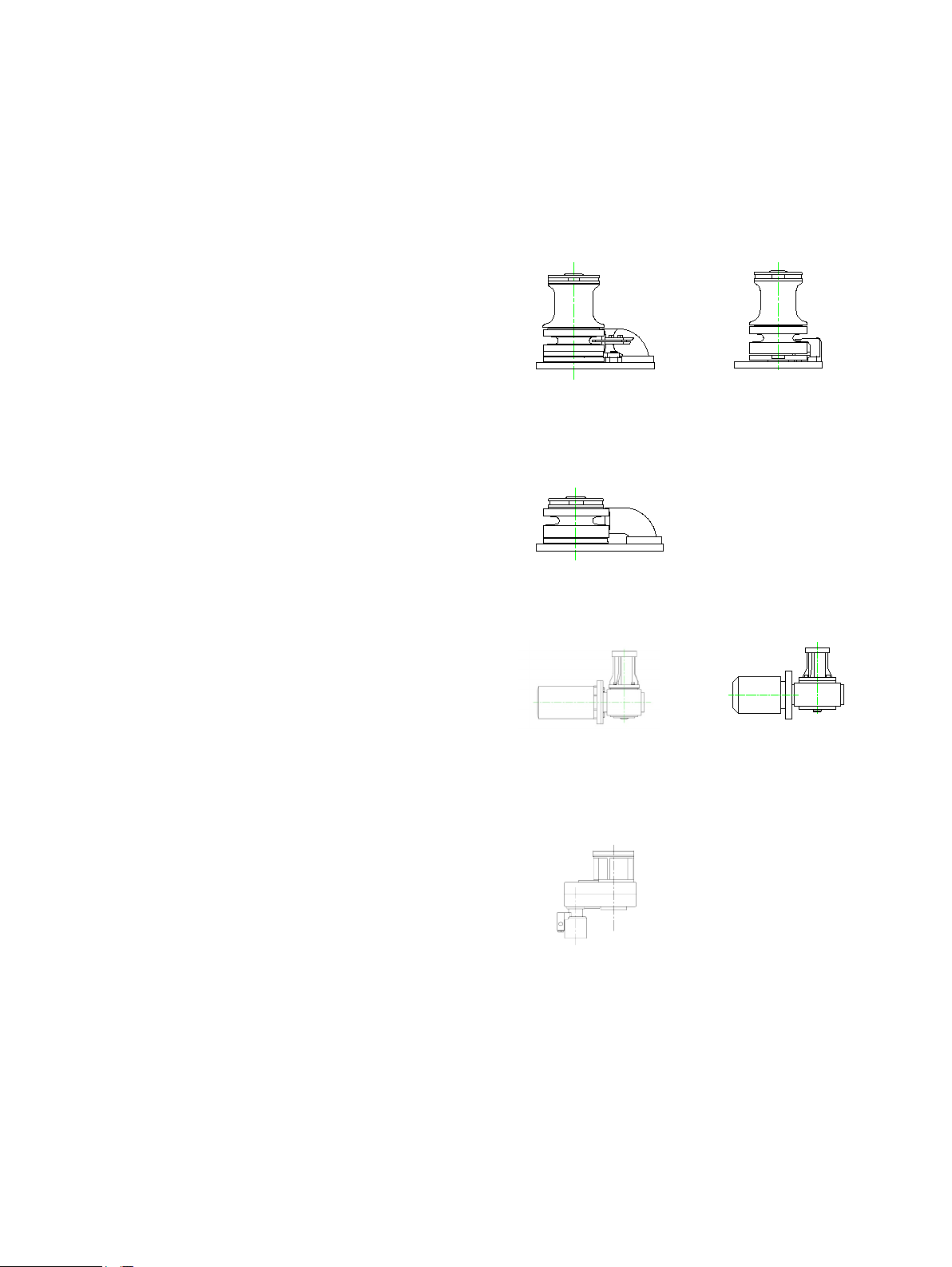
1.2 PRODUCT VARIATIONS
There are two options of above-deck arangements or
“topworks”, combined with four types of drives.
The types of topworks are:
VWC - vertical windlass with chainpipe
VWCLP - vertical windlass with chainpipe, low prole
Each of the above topworks is available as clockwise
or anticlockwise conguration (see description of
Denition of rotation in Section 2.1).
Beside friction clutch, which can be used for controlling
chain speed while free falling anchor, the windlasses
can also be equipped with an external band brake.
Picture 1.1
VWC topworks
Picture 1.2
VW topworks
The types of drives are:
Electric DC drive (24V)
Electric AC drive (horizontal motor)
Hydraulic drive
The above deck components of the windlass can come
in several different materials / nishes:
Chrome over polished bronze
Bare polished bronze
Stainless steel
Titanium nitride coated bronze or stainless steel
Picture 1.3
VWCLP topworks
Picture 1.4
Electric DC drive
Picture 1.6
Hydraulic drive
Picture 1.5
Electric AC drive
Page 6

6
1.3 SPECIFICATIONS
General
Maximum stud link chain size 16mm
Maximum short link chain size 19mm (3/4”)
Maximum pull capacity at chainwheel 2730kg (6006lb)
Electric DC Drive
Chain speed at 1000kg load 10m/min (33ft/min)
Continuous pull capacity at chainwheel 680kg (1496lb)
Current at 1000kg load 215A
Motor power 3.5kW (48HP)
Weight of windlass 195kg (429lb)
Electric AC Drive
Vertical motor Horizontal motor
Chain speed 15m/min (49ft/min) 13m/min (43ft/min)
Continuous pull capacity at chainwheel 1490kg (3278lb) 1286kg (2829lb)
Current at continuous pull rating (@ 400V) 8.7A 8.2A
Current at start-up (@ 400V DOL) 47A 55A
Motor power 4kW (5.5HP) 4kW (5.5HP)
Weight of windlass 285kg (627lb) 247kg (543lb)
Hydraulic Drive
Chain speed (at Recommended ow) 14m/min (47ft/min)
Recommended hydraulic oil ow 41l/min (11USgal/min)
Maximum hydraulic oil ow 76l/min (20USgal/min)
Continuous pull capacity at chainwheel 2730kg (6006lb)
Maximum hydraulic oil pressure 138bar (2000psi)
Motor port size (pressure and return) 7/8” x 14tpi UNF - SAE 10
Minimum size of oil supply/return lines 16mm (5/8”)
Weight of windlass 153kg (337lb)
*See Appendix C for other options of ow and pressure.
Rated capacity and chain speed is based
on the chainwheel for 16mm chain. The
performance may vary slightly when other
chainwheels are used.
Page 7

Hydraulic oil characteristics
Viscosity: ISO 32 - 68 (at 20ºC)
Suitable oils:
Shell Rimula X 15W-40
Shell Myrina M 15W-40
Penzoil SAE 10W-40
Texaco 2109 SAE 15W
Texaco 1814 SAE 10W-40
BP HLPHM 32-68
BP Autrans T0410
Castrol Hyspin AWS 32-68
Minimum 0.125% Zinc anti-wear additive.
7
Chainwheels
The chainwheel numbers consist of two parts: main
part number and sufx, for example 2514-001.
The main part number refers to the type of chainwheel
and the sufx refers to size and type of chain.
Types of chainwheels
2513 for windlasses without band brake
2514 for windlasses with band brake
Sufxes
Sufx Chain to t
001 16mm PWB, Campbel, EN818-3
002 14mm EN818-3; 13mm GR4
1/2” G40 (ISO) & G63 ACCO
003 16mm DIN 766; 5/8” G4 ACCO (ISO)
004 13mm PWB, Weissenfels
008 13mm DIN 766
010 14mm stud link
011 16mm stud link
012 12.5mm stud link
013 12mm EN818-3
There are other chainwheel models less commonly
used. Contact your Maxwell distributor for details.
Page 8
8
2.0 INSTALLATION
2.1 SELECTION OF POSITION FOR THE WINDLASS
Windlasses of this size will often be installed in
pairs, giving an emergency backup in the event of
mechanical or electrical failure. In this case one of the
windlasses will normally be retrieving anchor running
clockwise and the other anticlockwise.
Position of the windlass should be selected together
Denition of rotation
The windlass is called a “clockwise windlass” if
it rotates clockwise, viewed from above, when
retrieving the ground tackle.
with positions of hawse pipe and spurling pipe.
The deckplate should be installed pointing with its
narrower end in the direction of the incoming chain.
That allows the chain to have maximum engagement
with the chainwheel.
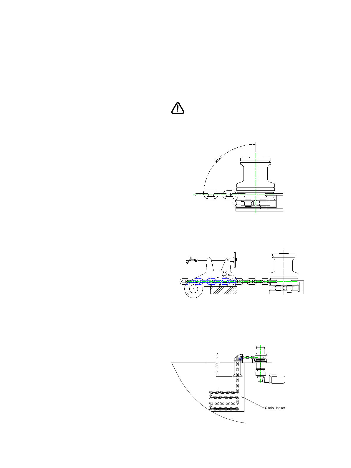
Allow the chain a straight run from the bow roller to
the chainwheel with no more than a 2° deviation from
horizontal (Picture 2.1).
The bow roller should have a vertical groove to suit
the prole of the chain. Its centre line should be
tangentional to the chainwheel (Picture 2.2). This
will align the chain so that it enters the chainwheel
without twisting.
When positioning the windlass, make sure that there
Direction of chain entering the chainwheel
is room to swing the clutch lever, so that it will clear
the pulpit and life lines or bulwark.
The tting of a chain stopper is essential to take the
load off the windlass while the vessel is at anchor. It
must be correctly aligned with the direction of chain
and installed at appropriate height to avoid the chain
rubbing over chain stopper body or pawl. Make sure
the chain stopper clears the anchor stock.
A tensioner device to tension the anchor into its
pocket is recommended. If the anchor is not snug in
the pocket, it could cause damage to the pocket in a
heavy seaway.
Correct height of Chain Stopper
Ensure a minimum of 800mm (32") clearance
between the end of spurling pipe and the chain piled
up in the chain locker. This will assist kinks, which
may develop in outgoing chain, to shake free.
The chain must gravity feed into the locker. If the
chainpipe cannot be positioned directly over the
locker, a heavy wall pipe can be used to direct
the chain to the required area. It is important that
the chain slips through the pipe easily, completely
unaided, sharp corners should be avoided. It may
be necessary to provide the pipe with a bell mouth
or to bell mouth the entrance to the chainpipe from
the locker to assist the free ow of the chain from the
locker.
The chain locker must be of such a size and shape
that the chain will heap up and feed out naturally
without fouling.
Recommended free space in chain locker
Picture 2.1
Picture 2.2
Picture 2.3
Page 9

9
If it can be arranged, the chain locker bulkhead should
pass between the chainpipe outlet in the deckplate
and the gearbox. This will keep the gearbox, motor
and power lines dry and away from aying chain.
Access for servicing from inside the cabin area can
usually be arranged through a locker.
Note that the gearbox can be indexed through a
number of different angles in relation to the windlass
deckplate. Be sure to select the most convenient
arrangement at installation and ensure incoming
chain well clears the gearbox, motor and power
supply lines.
To ensure safe position of the operator while tailing
from the warping drum, footswitches should be
positioned at least 500mm (20”) away from the
windlass.
The below deck portion of the footswitch should not
be exposed to water or wet environment and the
breather holes must be kept clear. The arrows on
the footswitches should be arranged to indicate the
direction of operation.
The motor starter (solenoid valves for hydraulic
windlasses) should be located in a dry area in close
proximity to the windlass. It must not be located in the
wet environment of the chain locker.
The breaker/isolator panel (DC powered windlasses
only) is selected to provide limited overload protection
for the motor and full protection for the supply cables.
It also provides the means for isolating the electrical
system from the battery.
This should be mounted in a dry place within 1.8m
(72”) of cable length from battery.
This equipment or equivalent is mandatory to meet
U.S.C.G. requirements.
Picture 2.4
Positions of drive, relative to topwork
2.2 PREPARATION OF MOUNTING AREA
It is of paramount importance that the vessel has
sufcient deck reinforcing and total structural strength
to sustain the loads that can be transmitted to the
mounting area of the windlass and chain stopper.
This should be equal to the loading of the equipment
to beyond breaking strength of the chain.
The mounting area for the windlass must be perfectly
at and rigid. A structural grade ller can be used
to level this area if initial atness is inadequate.
Mounting area for the chain stopper should be
prepared at the same time. The chain stopper has to
be installed at an appropriate height to ensure that
chain lays horizontally when it comes out of the chain
Page 10
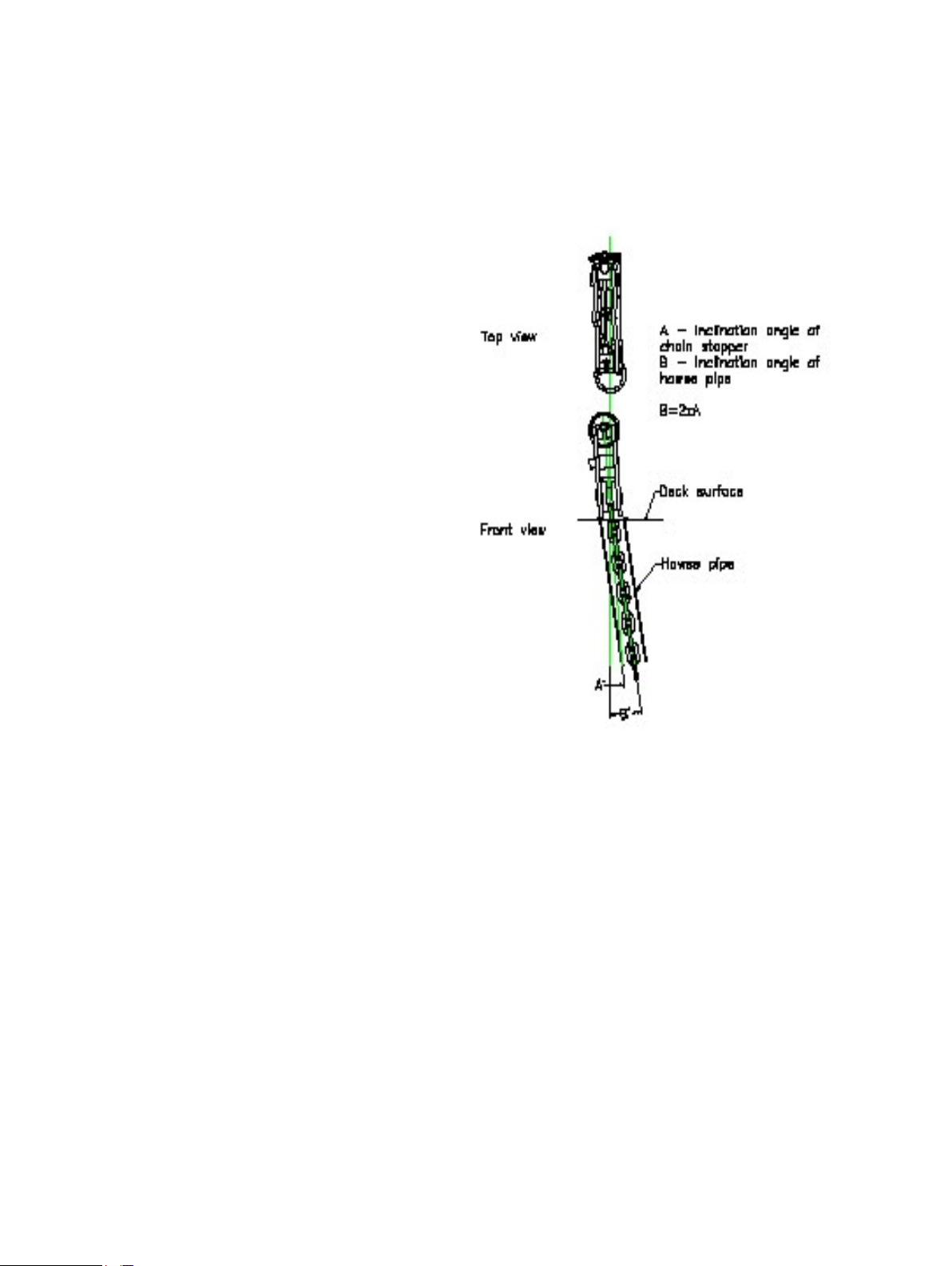
stopper and into windlass. Maximum allowed angle
deviation in vertical plane is ±2°.
If hawse pipe is angled outboard from deck to anchor
pocket, the chain stopper should also be angled by
half of the angle of the hawse pipe (Picture 2.5). That
will help to reduce twisting of the chain between the
chain stopper and the windlass and ensure good t of
the chain into the chainwheel. The chain stopper can
be installed vertically if the hawse pipe angle is less
than 4°.
A deck cutout detail drawing is enclosed with these
instructions to assist in marking out all the drilling and
cutting required for installing the windlass. Before
drilling and cutting, check the marked out area is
dimensionally correct and make any necessary
corrections.
The hole for mounting band brake guide (where
applicable) should be marked and drilled after
assembling the band brake on the windlass.
10
2.3 PREPARATION OF THE WINDLASS
Remove windlass from its packing case.
Disassemble it in the following order (refer to
drawing in Appendix B):
• Remove the Cap and O-Ring from the top of the
windlass, taking care not to damage the chromed
surface.
• Undo and remove the Retaining Screw and
Retaining Washer under the Cap, using a at
screwdriver.
• Undo and remove Clutch Nut, remove Drum and
Upper Clutch Cone .
• On VWC & VWCLP versions, undo Screws that
retain Chainpipe and remove it. On VW versions
undo Screws and remove Stripper.
• Remove Plungers, springs, upper spring holder,
Chainwheel, Lower Clutch Cone and Key. The
Lower Clutch Cone might be held by a Grub
Screw to the shaft. If that is the case, undo the
Grub Screw before removing the cone. Make sure
not to displace the two Retention Clips that were
supporting the Lower Clutch Cone.
• Carefully remove Deck Seal to avoid damage to
it.
• Undo Screws and remove the Deckplate.
• Refer to Appendix B of this Manual and identify
all parts. If any parts are damaged or missing,
contact your Maxwell distributor. Some smaller
parts might not be assembled on the windlass
by the factory, but supplied in a plastic bag in the
packing case.
Picture 2.5
Installation angle of chain stopper
Page 11
11
Maxwell strongly recommends generous application
of a high quality anti-corrosive paste or coating to
the mating sections of main shaft, drive key, anges,
screw threads, dowels and other surfaces that are
likely to seize after being in contact for a prolonged
period of time.
Also ensure anti-corrosive coating is liberally applied
to the inside wall of the Spacer Tube.
2.4 INSTALLING THE WINDLASS
Refer to the drawing in Appendix B for help with
identifying components and installing them correctly.
Extra care should be exercised when handling
polished parts to avoid any damage to polished
surfaces.
When assembling the parts, apply an anti-seize
compound generously over all screw threads, keys
and keyways, Mainshaft and inside the spacer tube.
Proceed with installation in the following order:
• After cutting holes for the windlass in the deck,
apply an appropriate bedding/sealing compound
to the clean surface, place Deck Gasket and
bolt the Deckplate to the deck using Mounting
Screws, and Insulating Bushes. Tighten them
evenly to 80 Nm (60 ft lb). Heel Block should
already be assembled to Deckplate.
• Offer up, from below deck, the drive assembly
sliding the Mainshaft through the Deckplate,
taking care not to damage the deck bearing.
• After aligning them correctly, bolt the Deckplate
and Spacer Tube together, from above deck,
using the Hex Head Screws and Spring Washers.
Tighten them evenly to 80 Nm (60 ft lb).
• Re-check that the position of the drive assembly
is satisfactory and convenient for connecting
power supply lines to the motor. Also, make sure
that the drive is not in the way of chain coming
into the locker.
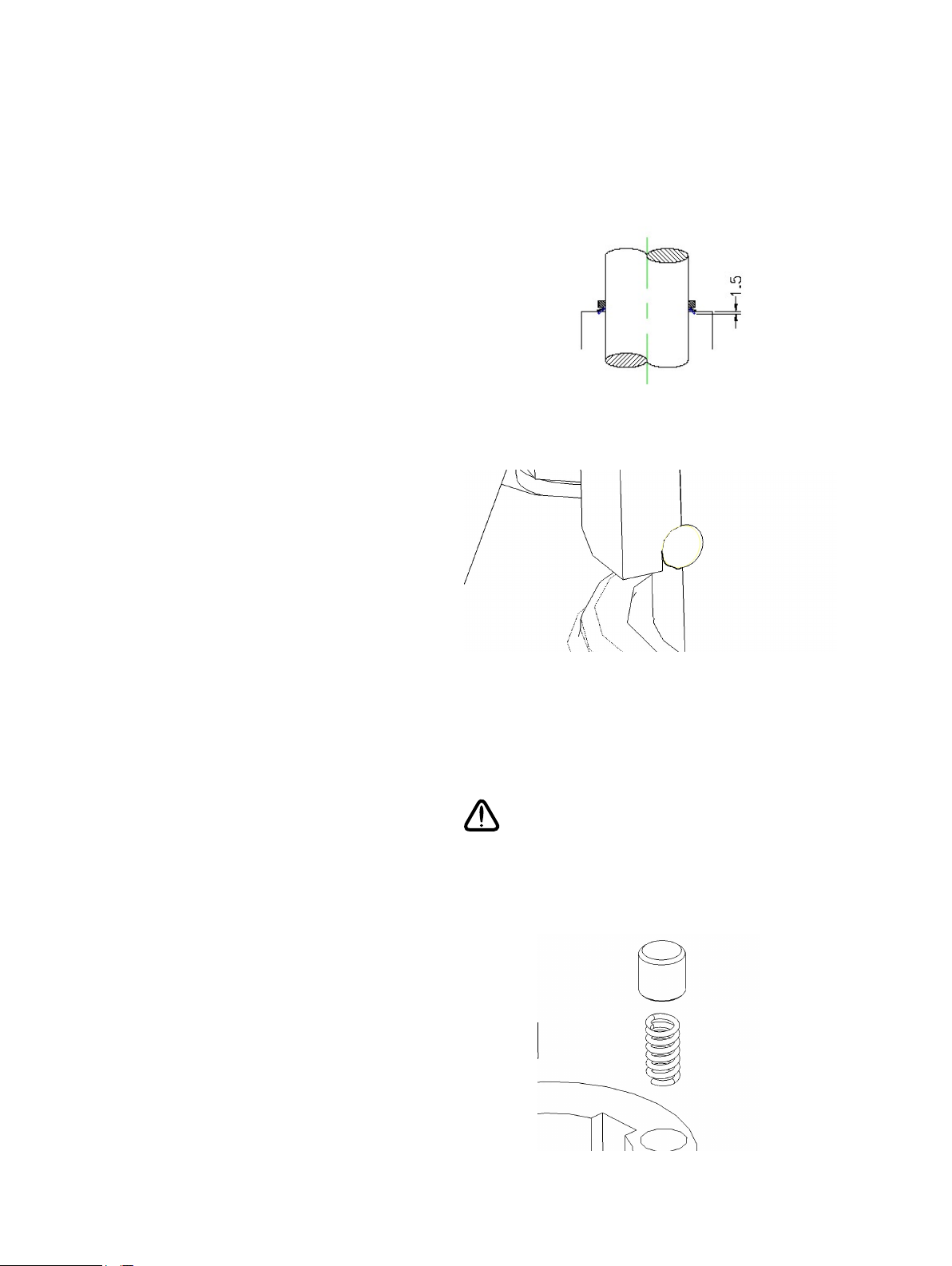
• If a chain counter is used, its sensor should be
tted into the Ø15mm hole in the Deckplate,
currently covered with a Plastic Plug. Make sure
the deck is drilled below for the sensor cable.
See brochure supplied with Chain Counter for
detailed assembly instructions.
• Grease Deck Seal and carefully slide it down
the Mainshaft. Push it against the Deck Bearing
(28) by approx 1.5 mm after initial contact (see
Picture 2.8).
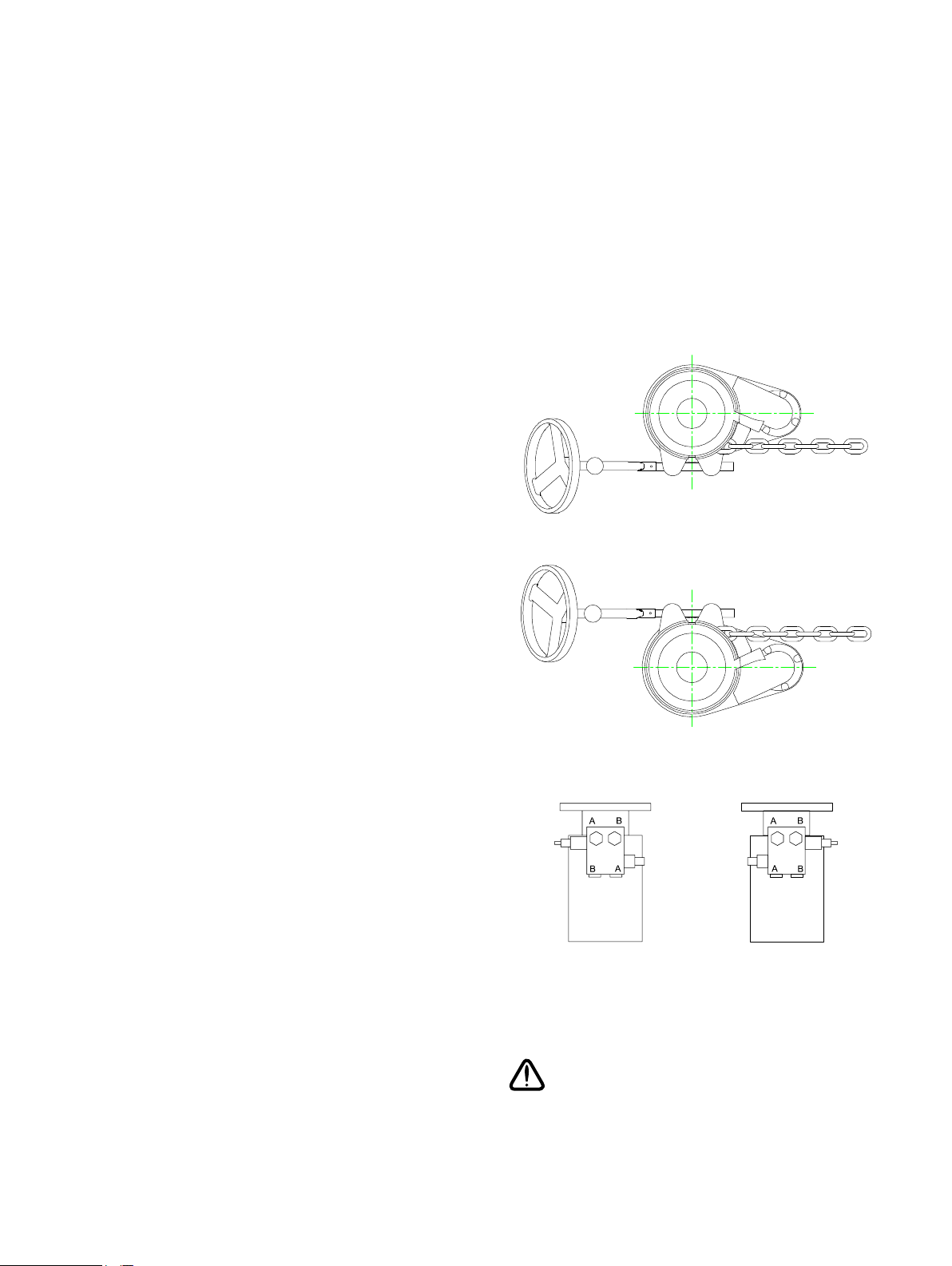
Picture 2.6
Clockwise topwork
Picture 2.7
Anticlockwise topwork
clockwise
windlass
Picture 2.8
Positions of valves on hydraulic motors
When assembling hydraulic drives, take
care not to swap over the drives (couple the
clockwise motor and gearbox to anticlockwise
topworks). See letters on Picture 2.8 for drive
identication.
anticlockwise
windlass
Page 12
• Insert the two Retention Clips into the groove in
the Mainshaft; apply some grease to help keep
them in position.
• Apply anti-seize compound generously over
the Mainshaft and keyway. Insert Key into the
keyway in the Mainshaft.
• Assemble the Lower Clutch Cone making sure it
sits nicely on the retention clips (see Picture 2.9).
Apply Lithium based marine grease generously
to the conical surface of the Lower Clutch Cone,
to assist with free falling the anchor.
• Install 6 springs and Plungers into holes in the
Lower Clutch Cone.
• Install Chainwheel, Upper Spring Holder and the
remaining 3 Plungers and springs.
• Install Band Brake (if applicable) on the
Chainwheel, putting its two stops one each side
of Heel Block. The Band Brake can be assembled
with its handle pointing either direction, choose
more convenient option.
• Make sure the band sits at on the shoulder at
the lower end of the Chainwheel and tighten the
brake by turning the Lead Screw. Slide shaft
guide (5 – Band brake) on Handle Shaft (6
– Band brake). Line up both parts of the Lead
Screw Assembly in one vertical plane and make
sure the bottom surface of the Shaft Guide sits
at on the deck.
• Mark up the position of the Shaft Guide on deck,
then remove the guide and drill Ø13mm clearance
hole in the deck for the retaining screw (not
supplied). The Shaft guide has a mounting hole
M12 x 25mm deep and should be retained from
under the deck with a M12 bolt of appropriate
length (depending on the deck thickness).
• Apply the same bedding/sealing compound as
used under the deck plate, replace the Shaft
guide and retain it from underneath.
• Slide the Retaining Nut (2 – Band brake) on
the Shaft (6 – Band brake) and insert the Pin (3
– Band brake) into the hole in the Shaft. Then put
on the Handwheel (1 – Band brake), making sure
the end of the Shaft comes into the square recess
in the Handwheel, and fasten it with the Retaining
Nut.
• Install Chainpipe and retain it with the 3 cap
screws. Note that there are three Spacers
supplied for the Stripper. They should be used
to adjust the position (height) of the Stripper.
The correct height is when the Stripper is in, or
as close as possible to the centre of the central
12
Picture 2.9
Installing Deck Seal
Picture 2.10
Lower Clutch Cone Assembly
For effective operation of the band brake,
the friction lining must remain free from
contamination by any lubricant. Lithium
complex base grease should, however, be
applied to the lead screw thread.
Picture 2.11
Plunger and Spring Assembly
Page 13

13
groove of the Chainwheel.
• Slide Upper Clutch Cone. Note that this cone has
friction lining, which SHOULD NOT be greased,
unlike the lower cone.
• Assemble Drum on top of the clutch cone (VWC
models only).
• Assemble Clutch Nut.
• Put Retaining Washer on top of the Mainshaft
and secure it with the Screw.
• Insert Cap into the Clutch Nut.
2.5 SELECTION OF MOTOR STARTER
Several AC motor starter options for windlasses are
available, each with characteristic current demands
and start load limitations. Maxwell recommends that
selection of the best motor start system be entrusted
to experienced persons familiar with anchoring
procedures and the vessels generating capacity.
"Direct On Line" starter is the simplest way of starting
an AC motor and it will allow the windlass to start
under full rated load. However, this method requires
relatively high momentary starting current, which the
generators may have adverse effect to the rest of
the electrical system on board. See specications
for current values at 400V in Section 1.3 and make
sure to recalculate it for the voltage used on board.
Start current may be limited to about half the above
amount by using a "Star-Delta" starter. However, start
torque is thereby limited to loads of about 25-30% of
the windlass rated capacity.
“Star-delta” and “soft starters” are not recommended
for starting windlass motors, as the motor torque is
severely limited during start up period. Since these
motors often have to start under load (when retrieving
the ground tackle), they might not be able to move
until they reach the full voltage and torque. The
benet of starting at lower current would therefore be
lost. Also, the motor brake would release immediately
on start-up, which could cause short movement of the
chain in opposite direction.
The Variable Frequency Drives (VFD) offer accurate
control of current during start up period while keeping
high motor torque. They also offer various other
benets like:
• innite speed control
• running the windlass over its nominal speed
• accurate current overload and thermal overload
control
The selection of the type of motor starter
should be done by a qualied electrical
engineer, taking into consideration the power
generating capacity on board.
Maxwell offers both advice and different types
of custom made starters to complement our
windlasses.
The “up” and “down” start contactors must
be mechanically or electrically interlocked
to safeguard the motor, in the event that an
accidental attempt is made to start the motor
in both directions simultaneously.
Page 14

14
Both “Direct On Line” starters and Variable Frequency
Drives are suitable and available from Maxwell,
customised to suit the anchor windlass and stern
capstan application.
2.6 POWER CONNECTIONS TO AC MOTOR
Remove the motor terminal box cover and take care
not to misplace the sealing gasket and screws.
Select a suitably sized, waterproof cable gland for
the armoured supply cable. The selected gland tting
must t the terminal box, be capable of anchoring the
armoured cable, and allow an effective waterproof
entry seal to be made.
Make the line connections to motor terminals. Make
also an effective earth connection.
Separately and similarly, enter the 2 thermistor cables
to the motor terminal box, and connect to the two
auxiliary terminal connectors of the thermistor circuit.
Check:
• Is the direction of rotation of the motor correct?
• Are cables satisfactorily xed?
• Are cable entry points to motor terminal box
satisfactorily waterproofed?
Spray the cable gland, cable entry points and motor
terminal box with anti-corrosive waterproof coating
"CRC 3013 Soft Seal" or equivalent.
Page 15

15
2.7 POWER CONNECTIONS TO DC MOTOR
The main power system is a two cable, ungrounded,
fully insulated, negative return system. The motor is
of the isolated earth type. This system is selected to
minimise electrolytic corrosion problems.
The DC motor has four power terminals, marked 1-4.
They should be connected to the starter box as per
schematic P101807 in Appendix C.
After connecting the cables, spray all terminals with
anti-corrosive waterproof coating, “CRC 3013 Soft
Seal” or equivalent.
2.8 POWER CONNECTIONS TO HYDRAULIC MOTOR
A basic hydraulic schematic is shown in Appendix C.
Port sizes on the hydraulic motor and minimum hose
sizes are specied in Section 1.3.
The motor is supplied with oil through two ports on
the Counterbalance Valve Block. They should be
connected to a bi-directional, solenoid controlled valve
(not supplied by Maxwell). The pressure line (when
retrieving the anchor) should be connected to the port B
and the return line to the port A (see Picture 2.8).
After connecting the power lines, spray all ports and
ttings with anti-corrosive waterproof coating, “CRC
3013 Soft Seal” or equivalent.
Page 16

2.9 INSTALLATION OF CONTROLS
The windlass can be operated using:
• Deck mounted footswitches
• Hand held pendant controller (single or dual
speed)
• Helm switch (single or dual speed)
• Chain counter
These control accessories are available from Maxwell
customised to suit your windlass.
It is the choice of the designer/builder to use one,
two or all three of these controls. They are wired
in parallel to the directional valve (for hydraulic
windlasses) or to the starter unit (for electric
windlasses). The controls can work on 12 or 24V
power supply.
If footswitches are used, then an isolator switch for
them must be installed in the wheelhouse, to prevent
operating the windlass by someone accidentally
stepping on the footswitch.
Hand held pendant controller is often the most
convenient way of operating the windlass. Maxwell
offers several variations of pendants, including single
speed, dual speed, single pendant for running a pair
of windlasses, pendants with auxiliary buttons which
can be used for starting chain wash system, hydraulic
pump etc. They are supplied with a plug on the other
end of cable and a matching waterproof socket,
which should be installed on a convenient location
on the deck.
All units are supplied with detailed wiring instructions
to assist installation.
Refer to wiring schematics in Appendix C for control
circuits. All control wiring should be done using no
smaller than 1.5mm² wire (AWG 16).
Where applicable, a manually resetable, ignition proof
3A breaker or fuse should be installed on the power
supply line for controls, within 1m (40”) from the main
breaker/isolator. These requirements are mandatory
to meet USCG, ABYC and NMMA rules.
After connecting the power lines, spray all ports and
ttings with anti-corrosive waterproof coating “CRC
3013 Soft Seal” or equivalent.
16
Picture 2.15
Pendant controller for operating two windlasses
Page 17

17
2.10 NOTE TO BOAT BUILDER
Experience has shown that, on long ocean
deliveries, sulphur from the ship's exhaust can settle
on polished surfaces, which can affect the quality of
the nish.
Please ensure that, upon completion of installation,
the windlass is treated with suitable corrosion
protective coating (“CRC 3097 Long Life”) and
wrapped in plastic lm. This ensures that your
customer receives the windlass from you in the
same top quality condition as you received it from
Maxwell.
Page 18

3.0 USING THE WINDLASS
3.1 PERSONAL SAFETY WARNINGS
• As with all load carrying equipment, the
consequences of heavy overload, neglect or
misuse may be unexpected failure and exposure
of crew and/or vessel to risk. Operate the
windlass with extreme care at all times.
• Before testing the windlass for the rst time,
check that all the wiring has been done correctly.
• When using the windlass, at all times practice
good seamanship and adhere to the following
rules in order to avoid any likelihood of injury or
accident.
• At all times keep hands, feet, loose clothing,
cordage and your hair WELL CLEAR.
• Never operate the windlass from a remote station
without maintaining a clear view of it and having
made sure that everyone is well clear of the
windlass, anchor and chain.
• Never use the windlass under power with
the clutch handle inserted into clutch nut or
emergency crank collar.
• When engaging the pawl while chain is running,
keep ngers away from the chain. Use clutch nut
lever, underneath and guarded by the chainpipe.
• Always motor up to the anchor position before
retrieving it from the bottom. Do not use the
windlass to pull the boat to the anchor.
• If the anchor is fouled, do not use the windlass
to break it out. With the chain stopper taking the
load, use the boat’s engine to break the anchor
loose.
• When lowering the anchor under manual control,
use the band brake or friction clutch (if tted) to
control the speed of the chain. Never lower the
anchor without maintaining safe chain speed.
• When the windlass is not in use, make sure the
power supply is isolated, making an accidental
operation thereby impossible.
• Do not use the windlass as an anchoring point
for the chain. Engage the chain stopper when the
windlass is not in operation.
• Never proceed at speed without rst ensuring
that the chain stopper is engaged. Also engage
the tensioner to keep the anchor snug in the
pocket.
• When using the windlass, do not switch
immediately from one direction of rotation to the
other, without waiting for windlass to stop. Abuse
is not covered by warranty.
Page 19

19
3.2 LOWERING THE ANCHOR UNDER POWER
• Ensure the clutch is fully engaged by inserting the
clutch nut lever in one of the slots on the clutch
nut, and turning clockwise rmly. The windlass
is equipped with a friction clutch, so it can be
engaged in any position (there is no need to
match the position of the opposite sides of the
clutch before engaging it).
• Remove clutch handle.
• Release band brake or pawl (whichever is
tted).
• Disengage chain stopper and chain tensioner (if
tted). To disengage the chain stopper pawl the
windlass may require momentary jogging in the
up direction.
• The windlass may now be lowered under power
by operating either the hand held pendant control,
helm switch or footswitch.
• When nished, turn off the isolator switch for the
controls.
3.3 RETRIEVING THE ANCHOR UNDER POWER
• Ensure the clutch is engaged, as described
above, and band brake or pawl is released.
• Remove clutch handle from the clutch nut.
• If a pawl type chain stopper is used, it can be left
ratchetting on the chain, so it will engage itself
automatically when the windlass stops.
• The windlass may now be operated to raise the
anchor.
• After retrieving the anchor make sure the chain
stopper and tensioner are engaged.
• Turn off the isolator switch for the controls.
As a safety feature all buttons on the controls
(pendant, toggle switch or footswitch) are
non-latching and the windlass will continue to
operate up or down only while they are held in
the engaged position.
Picture 3.1
Engaging the clutch
It is regarded as sound practice to motor
over the anchor position and so reduce chain
tension. This will also help the anchor to break
out, reduce the power consumption and reduce
load on the windlass and deck gear.
Care should be exercised when docking the
anchor to avoid damage to the anchor pocket.
Jog in the last meter (3-4’) of the chain
carefully seating the anchor home.
3.4 LOWERING THE ANCHOR UNDER MANUAL CONTROL
This method will normally be employed to lower
the anchor quickly, to lower it in "quiet ship" and in
emergencies (power loss or control failure).
Proceed as follows:
• Tighten the clutch and band brake (if tted).
• Release the chain stopper and chain tensioner.
If the anchor has to be lowered in case of power
loss and pawl on the chain stopper is engaged
and under tension (by chain), to release it, pull
the chain in slightly, using tensioner. Once the
pawl is disengaged, release the tensioner and
Page 20

20
disengage it. If there is too much slack in the
chain, it might be necessary to remove the domed
nut from the end of lead screw and release the
It is considered potentially dangerous to allow
the chain to free fall in an unrestricted manner
- always control the chain speed.
screw completely. If doing that, make sure the
band brake and clutch is still engaged, for safety
reasons.
• Fully disengage the clutch by turning the clutch
nut anticlockwise until it comes to a stop.
• Slowly release the band brake in a controlled
manner. The chain should now release, the
weight of self-launching anchor being sufcient to
draw out the chain. Regulate the chain speed by
gradually engaging/disengaging the band brake.
• When the required amount of chain is out, tighten
the band brake and engage the chain stopper.
• If the band brake is not tted, the speed of chain
can be controlled by the clutch. In that case, after
disengaging the chain stopper, slowly release the
clutch by inserting the lever into the clutch nut
and turning it anti-clockwise. Regulate the chain
speed by gradually engaging/disengaging the
clutch.
Chain Roller-Stopper-Tensioner
The chain slack between the tensioner and
the windlass should be kept to less than the
end travel of the tensioner. This allows for safe
disengagement of the tensioner and transfer of
load to the chainwheel.
3.5 OPERATING THE WARPING DRUM INDEPENDENTLY
This is applicable to VW and VWC models only.
The drum can be operated independently of the
chainwheel and can be used to manage docking
lines or a second anchor. To use in this way, proceed
as follows:
While handling docking lines with the capstan,
ensure everyone stays well clear of the lines
and the capstan.
• Engage the chain stopper, the pawl or the band
brake (whichever is tted).
• Fully disengage the clutch as described in
Section 3.4.
The drum may now be operated independently of
the chainwheel. Maxwell recommends all warping
operations be controlled by the footswitch. This
makes it a one-person operation and offers better
control of the capstan in case of emergency.
Take several turns of the warping line around the
drum and pull on the rope tail with sufcient manual
force to provide good grip of the line to the drum,
Take care not to allow “riding turns”. This is
caused by the loaded line climbing on top of
lower loaded coils on the drum. A riding turn
can only be removed by paying the line out to
the point where the riding turn is created.
whilst operating the footswitch. Make sure the drum is
operated in the same direction as the line is wrapped
around it.
Do not engage more turns on the drum than are
necessary to accomplish the task. Whilst docking,
wind and tide can impose sudden and excessive line
tension. It is recommended to allow slipping to occur
at the drum. This will protect the capstan, docking
lines and vessel from damage.
Picture 3.2
Page 21

4.0 MAINTENANCE
4.1 WINDLASS MAINTENANCE
21
Every six months disassemble the above deck
components of the windlass (up to the Deckplate) as
described in Section 2.3. Clean all components and
check for damage. Grease the components using
lithium complex base, water proof grease, especially
grease the conical surface on the Lower Clutch Cone,
Upper Clutch Cone has a friction lining and should
not be greased. Grease bearing in the Deckplate
through the Grease Nipple.
Clean chromed surfaces with a cloth, damp with
kerosene. After cleaning spray them with “CRC 3037
Long Life” or alternatively, with “CRC 6-66” or “WD40”. Regular use of “CRC3097 Long Life” will assist in
maintaining the bright chrome nish.
Re-assemble in the reversed order.
Inspect the components below deck for corrosion,
chipped paint etc, clean them, touch up the paint if
necessary. Spray them for protection with “CRC 3013
Soft Seal”.
The gearbox on electric windlasses is lubricated for
life and, as such, does not need periodical oil change.
Once installed correctly, it should give many years of
trouble free service without maintenance.
If, for any reason, the oil in the gearbox has to
be replaced, use Shell Tivela Oil SC320. If not
available, another synthetic oil of equivalent viscosity
characteristics can be used.
The gearbox on hydraulic windlasses is lled with
synthetic oil, which should be changed every three
years. When changing the oil, take the gearbox of
the windlass together with the motor because motor
ange acts as a seal to the lower end of the gearbox.
Turn the gearbox up side down and then take the
motor off. When the new oil is lled up, the oil level
should be up to the centre of the Sight Glass (refer
– Gearbox assembly – appendix B).
Before doing any maintenance work on electric
motor, starter units and wiring, make sure the
power supply is switched off.
Use synthetic oils only. Never mix two oils, even
if they are from the same manufacturer.
Page 22

4.2 BAND BRAKE MAINTENANCE
The frequency of brake lining renewal will depend
entirely on its usage. Should visual inspection reveal
that the lining thickness has worn to below 2mm or if
the ends of brake band can touch each other when
tight, renewal of brake lining is necessary.
Grease the band brake lead screw at least every
three months.
Avoid grease contamination of brake friction linings.
4.3 RECOMMENDED LUBRICANTS
Greases
- Lithium complex base NLG1 consistency No.
2
• CASTROL LMX
• DUCKHAMS Keenol
• FINA CERAN WR 2
• SHELL Retinex LX
• MOBIL Mobilgrease HP
22
Gearbox Oils
- ISO 3448 VG 320
• CASTROL Alpha MAX 320
• SHELL Tivela oil SC320
• MOBIL Mobilgear 632
• BP MACH GR XP 320
Anti-Corrosive Coatings
• CRC 3013 Soft Seal
• Boeshield T9
• Lanocote
Anti-Seize Coating
• International Paints Res-Q-Steel
Never mix greases, use only one type. If in doubt,
remove the previous lubricant and clean the parts
thoroughly before applying the new one.
Page 23

23
4.4 SPARE PARTS
Maxwell recommends a modest quantity of spare
parts to be ordered as familiarity with the windlass is
developed during installation. As small parts can be
lost during maintenance, keeping spares (and spare
tools) is recommended.
We recommend the following list of spare parts per
windlass to be carried on board:
Part No. Description Qty
3006 Retention clip 2
4809 Cap 1
SP2769 O-Ring 1
3566 Plunger 5
3567 Spring 5
Topworks key* 1
SP0718 Deck Seal 1
SP0840 External circlip** 1
*The part number will vary depending on the model,
see Appendix B.
**Hydraulic drives only.
If any other spare part is required, please refer to
Appendix B for the correct part number and contact
one of our distributors worldwide (Appendix D). When
ordering spare parts, please quote:
• Windlass model
• Serial number of the windlass
• Part number (see Appendix B)
• Part description
• Quantity required
4.5 TOOLS FOR MAINTENANCE
We recommend the following tools be kept on board
for disassembling and assembling the windlass:
• Set of metric hexagon keys (Allen keys) 5, 8, 10
and 14mm
• Ring/open end spanner 17, 19, 24mm
• Curved ring spanner (or socket spanner) 17mm
• Circlip pliers
Page 24

24
Check the fuse on power supply to controls
Check wiring for damage
If there is more than one type of control (pendant unit, footswitch,
helm switch), check them all in an effort to isolate the problem
Check isolator switch and fuse on Variable Frequency Motor
Control, if supplied
Check the power supply to controls from the source, step by step,
and identify the point where it stops
between 50 and 500 ohms. When doing that, do not use voltage
Incorrect or incomplete wiring Check wiring against the diagrams supplied
Damaged thermistors on the motor To conrm, check resistance across thermistors, it should be
Faulty thermistor relay To conrm, check resistance between terminals 21 and 22. If it is
above 500 ohms, contact Maxwell
Check main isolator switch
Check hydraulic pump (hydraulic windlasses only)
Check name plate on the motor. If conrmed, contact Maxwell
No power supply to the windlass Check power supply lines
Motor voltage does not match the power supply
on board
Make sure the bolts have spring washers, adjust bolt length
Hydraulic relief valve not set correctly Check valve setting
The mounting bolts of the motor are touching
persists, contact Maxwell
the motor winding
The clutch is not fully engaged Tighten the clutch up, as described in Section 3.2. If the problem
Band brake is engaged Release band brake
Electric AC motors: leave it to cool down and the thermistor relay
will reset itself automatically
Topworks key (26) not installed Install the key
The motor has been overloaded and has
reached its critical temperature
Problem Possible cause Solution
5.0 TROUBLESHOOTING
Windlass does not start No electric power to controls Make sure the isolator switch for windlass controls is on
Windlass is not able to pull the
specied load
DC motor draws high current but
struggles to pull the load
Windlass runs but the chainwheel
stays stationary
Electric motor stops after prolonged
heavy use
Page 25

25
Electric DC motors: leave it to cool down and reset the circuit
breaker
The clutch is not fully disengaged Disengage the clutch fully
The band brake is not disengaged Disengage the band brake fully
board
Plungers & springs (8,9) not tted Fit as described in Section 2.4
Check the installation. If the problem persists, some height
adjustments might have to be made
Chain twisted between windlass and bow roller Untwist the chain
Vertical angle of incoming chain bigger than 2
degrees (see Picture 2.1)
The anchor does not free fall Lower clutch cone is not greased Disassemble the cone (19), clean and grease the conical surface
Chain jumps / slips on the chainwheel The chainwheel not selected correctly Contact Maxwell with correct identication of the chain used on
Page 26

APPENDIX A - Dimensional drawings
26
Page 27

27
220
140
CUTOUT
90 Cutout
R
190
250
142.5
R
70
DO NOT USE AS A TEMPLATE
THIS IS FOR REFERENCE ONLY
(SEE NOTE 3)
on a 250 PCD.
8 holes
or tap M12 x 1.75 into deck adapter plate,
12.5 Through Deck
PORT AND STARBOARD FITTING
NOTES:
1. BEFORE CUTTING DECK, CHECK AL L
UNDERDECK CLEARANCES.
READ & UNDERSTAND INSTALLATIO N
INSTRUCTIONS CONTAINED WITHI N
THE MANUAL.
2. CHECK YOUR MARKED OUT DIMENSI ONS
CAREFULLY, BEFORE CUTTING & D RILLING.
DECK BOLT HOLES MUST BE DRIL LED PARALLEL
& SQUARE TO MOUNTING FACES.
3. MAXWELL MARINE IS NOT RESPON SIBLE FOR
ANY INACCURATE DATA, DUE TO R EPRODUCTION
ERRORS OF FAX MACHINES, PRINTE RS,
PHOTOCOPIERS ETC.
3815
3.00
Deck Cutout D etails - 6000 VW C
1
1:1
A2
Scale
0.5
of
Sheet
1
Description:
Material:
Revision No:
0.5
Tolerances if none specified
1 DECIMAL (X.X)
Drawing No:
ALL ANGLES
0.1
Sheet Size
2 DECIMAL (X.XX)
0.2
0 DECIMAL (X)
This drawing is protected by copyright and the design and or details
contained therein are the confidential property of
MAXWELL MARINE LTD.
This drawing must be returned upon demand and must not be copied,
loaned or have its contents communicated to any other persons,
including subcontractors, without the consent in writing from
Maxwell Marine Ltd. This drawing must not be used for any other
purpose other than that for which it was originally supplied.
R
e
v
.
C
h
a
n
g
e
M
a
d
e
o
n
D
e
s
/
D
r
a
w
n
2
.
0
0
I
s
s
u
e
d
i
n
C
A
D
3
/
8
/
0
4
A
N
3
.
0
0
T
e
m
p
l
a
t
e
n
o
t
e
a
d
d
e
d
.
N
o
t
e
s
r
e
v
i
s
e
d
2
9
/
3
/
0
6
R
P
Page 28

8 Holes drill
15
Equispaced on 310 PCD
This drawing is protected by copyright and the
design and or details contained therein
are the confidential property of
MAXWELL MARINE LTD.
This drawing must be returned upon demand
and must not be copied, loaned or have its
contents communicated to any other persons,
including subcontractors, without the consent
in writing from Maxwell Marine Ltd. This
drawing must not be used for any other purpose
other than that for which it was originally supplied.
Recommended line of
deck pad
Drawing No:
Revision No:
Description
Deck Cutout Details - 6000 8000 11000 VC - 6000 VW
3983 3.00
Date:
3/8/04
AH
Drawn:
Scale:
A2=1:1
NOTES:
1. BEFORE CUTTING DECK, CHECK ALL
UNDERDECK CLEARANCES.
READ & UNDERSTAND INSTALLATION
INSTRUCTIONS CONTAINED WITHIN
THE MANUAL.
2. CHECK YOUR MARKED OUT DIMENSIONS
CAREFULLY, BEFORE CUTTING & DRILLING.
DECK BOLT HOLES MUST BE DRILLED PARALLEL
& SQUARE TO MOUNTING FACES.
3. MAXWELL MARINE IS NOT RESPONSIBLE FOR
ANY INACCURATE DATA, DUE TO REPRODUCTION
ERRORS OF FAX MACHINES, PRINTERS,
PHOTOCOPIERS ETC.
DO NOT USE AS A TEMPLATE
THIS IS FOR REFERENCE ONLY
(SEE NOTE 3)
LINE OF DECK BEARING
PROFILE
Cutout for under deck spacertube
232
346
28
Page 29

APPENDIX B - Spare parts
293031
Page 30

Page 31

Page 32

32
Item Description Qty Part no.
1 Cap 1 4809
1.1 O-Ring 1 SP2769
2 Label 1 3740
3 Hex head bolt M10 x 25 1 SP0281
4 Retaining washer 1 1474
5 Clutch nut
VWC VW 1 3801C
VWC VW - S/S 1 5186
VWCLP 1 3839C
6 Drum
chromed bronze 1 2637C
stainless steel 1 5188
7 Upper clutch cone 1 P14180
8 Plunger 9 3566
9 Spring 9 3567
10 Upper spring holder 1 2640
11 Chainwheel*
Non band brake version 1 2513C
Band brake version 1 2514C
12 Socket head cap screw M12 x 40 12 6417
13 Heel block - chrome 1 3808C
Heel block - stainless steel 1 5193
14 Socket head cap screw M10 x 30 2 SP0169
15 Socket head cap screw M12 x 35 3 SP2481
16 Chainpipe
clockwise version 1 3755C
anticlockwise version 1 3756C
17 Spacer 3 3733
18 Stripper arm - VWC VWCLP 1 3732
Stripper arm - VW VWLP 1 6856
18.1 Cap Screw - M10 x 30 2 SP0169
18.2 Cap Screw - M10 x 50 2 SP2464
18.3 Stripper arm support - VW VWLP 1 6854
18.4 Dowel 2 6193
18.5 Stripper arm support spacer - VW VWLP 1-3 6855
19 Lower clutch cone 1 2641
20 Grub screw 1 SP0113
21 Retention clip 2 3006
22 Deck seal 1 SP0718
23 Plug 1 SP0875
23.1 Socket head grub screw 2 SP0111
24 Hex head bolt M12 x 60 8 SP0283
25 Spring washer M12 8 SP0475
Page 33

33
26 Topworks key
VWC VW 1 2638
VWCLP 1 3273
27 Insulating bush 8 3012
28 Deck bearing 1 3028
29
30 Deckplate
VWC VWCLP clockwise version 1 P14521
VWC VWCLP anticlockwise version 1 P14523
VWC VWCLP non- band brake version 1 P14167
VW VWLP clockwise and anticlockwise S/S 1 6852
30.1 VW VWLP Deckplate Lower 1 6853
31 Insulating gasket 1 3015
32 Main shaft (see table below for part numbers) 1
33 Threaded insert 8 SP0589
34 Spacer tube
DC & AC right angle drive 1 5262
AC vertical & hydraulic drive 1 2646
35 Gearbox key
DC & AC right angle drive 1 5265
AC vertical drive 1 3759
Hydraulic drive 1 3005
36 Socket head cap screw M12 x 35 8 SP2481
37 Socket head cap screw M10 x 35 8 SP2451
38 Nut M16 4 SP0327
39 Spring washer M16 4 SP0451
40 Flat washer M16 4 SP0421
41 Adaptor ange 1 4409
42 Hex head bolt M16 x 70 4 SP0297
43 Socket head cap screw M10 x 30 8 SP0169
44 Spring washer M10 8 SP0466
45 External circlip 2 SP0840
46 Gearbox
Electric DC drive 1 SP2999
Electric AC right angle drive 1 SP4117
47 Retaining washer 1 5201
48 Spring washer M10 1 SP0466
49 Socket head cap screw M10 x 25 1 SP0166
50 Socket head cap screw M12 x 50 4 SP0180
51 Spring washer M12 4 SP0475
52 Nut M12 4 SP0326
Page 34

34
53 Motor
Electric AC motor 208V - 60Hz two speed 1 SP3344
Electric AC motor 208V - 60Hz 1 SP3395
Electric AC motor 400V - 50Hz 1 SP3394
Electric AC motor 400V - 50Hz two speed 1 SP3335
Electric DC motor 24V 1 SP2993
54 Vertical AC drive
AC motor & gearbox 220V 50Hz 1 5317
AC motor & gearbox 208V 60Hz 1 5320
AC motor & gearbox 400V 50Hz 1 5321
AC motor & gearbox 400V 50Hz two speed 1 5322
55 Gearbox 1 P14153
56 Socket head cap screw M12 x 40 4 SP0160
57 Hydraulic motor **
26 l/mmin, 206 bar 1 SP0934
42 l/mmin, 138 bar 1 SP1064
57 l/mmin, 103 bar 1 SP1065
58 Counterbalance valve block 1 SP2226
User's Manual 1 P19137
Clutch nut lever (not shown) 1 3081
* see Section 1.3 for complete part number
** refer to gearbox drawing for motor pinion (item 16) and locking nut (item 17) part no.s
Main shaft part numbers
VWC VWCLP VW - S/S
Shaft Shaft Shaft Shaft Ext
DC & AC right angle drive 5263 5264
AC vertical drive 3757 5383
Hydraulic drive 2654 3378 6441 5370
Page 35

35
Band brake part numbers
Item Description Qty Part no.
1 Hand Wheel 1 6925
2 Dowel 1 6927
3 Bush 1 6926
4 Cap Screw 4 SP2459
5 Guide Bush 1 5545
6 Shaft Guide 1 5525
7 Band Brake 1
8 Threaded Boss 1 3654
9 Circlip 4 SP0846
10 Anchor Pin 1 3655
Lead Screw Assembly - Standard 1 P103819
11
12 Thrust Washer 1 3656
13 Locking Nut 1 3656
14 Roll Pin 1 SP0528
15 Stud - M12 1 4587
16 Flat washer - M12 1 SP0424
17 Spring washer - M12 1 SP0475
18 Hx Hd Nut - M12 1 SP0326
Lead Screw Assembly - Short Shaft 1 P103820
Lead Screw Assembly - Long Shaft 1 P103821
Page 36

36
8
1
2
3
4
7
8
9
12
13
14
15
16
17
18
19
7
4
20
3
2
1
14
13
14
5
6
7
11
9
9
8
10
Page 37

37
Item Description Qty Part no.
1 Oil seal 2 SP0715
2 Socket head capscrew M6 x 35 12 SP2483
3 Main shaft bearing 2 3043
4 Nut 3/8" 12 SP0322
5 Threaded insert 8 SP0587
6 Bolt - Hex Hd - 3-8 x 3in 304 SS 3 SP0267
7 Flat washer 12 SP0434
8 O-ring seal 4 SP0720
9 Oil plug 3 3263
10 Gear case upper 1 2686
11 Sight glass 1 3223
12 Thrust washer 1 SP0681
13 Thrust bearing 2 SP0639
14 Thrust washer 3 SP0640
15 Output gear 1 2664
16 Pinion 1 2674
17 Pinion nut 1 3039
18 Stud 3 3610
19 Gear case lower 1 2673
20 Threaded insert 4 SP0589
Page 38

38
APPENDIX C - Installation schematics
Page 39

39
Page 40

40
Page 41

Bridge or Wheel house
controls
LEGEND:
C1C2C3
S1
S2
Roving 2 button (up-down) hand held water proof controller
Bridge/Wheel House fixed windlass control UP/OFF/DOWN
Footswitch
Isolator switch for power supply to the controls
Manually resetable circut breaker 3A, recommended ETA
41-10-P10-G10-WT
Tinned multistrand conductors of at least 1.5mm2 must be used
for all control circuits
Directional valve
Power supply
to controls
24V DC
41
Page 42

42
APPENDIX D - Network of Agents and Distributors
EUROPE
Composite Works–authorized service agent
Croatia
Heli d.d. – authorized service agent
Sv. Polikarpa 8
52100 Pula
Tel. +385 52 37 55 00
Fax +385 52 37 55 10
Quai Francois Mitterrand 46
13600 La Ciotat
Tel. +33 4 42 83 83 00
Fax +33 4 42 83 83 04
mark.salman@compositeworks.com
Contact: Mark Salman
iurem@heliyachts.com
Contact: Ivan Urem
Italy
Denmark
Pro Marine
Nobilisvej 8
DK - 9320 Hjallerup
Denmark
Tel. +45 96 473 200
Fax +45 96 473 201
info@promarine.dk
Saim SpA
Via Donizetti 9-11
20090 Assago - MI
Italy
Tel. +39 02 4570 3394
Fax +39 02 4570 0663
marine@saim-group.com
Saim SpA
Lungomare della Salute 2
Germany
Sailtec GMBH
Hasselbinnen 28
D-22869 Schenefeld
Bei Hamburg
00054 Fiumicino (Rome)
Italy
Tel. +39 06 6502 9462
Fax +39 06 6502 9468
marine.roma@saim-group.com
Germany
Tel. +49 40 08229940
Fax. +49 40 08304279
Christian Gnass – cg@sailtec.de
Anja Czemper – ac@sailtec.de
Norway
Engbo AS
Ollebukta N-3110
Tonsberg
Norway
France
Saim France
Allee Francois Coli-Bat 13 F
Tel. +47 33 300 850
Fax +47 33 300 860
rmapost@engbo.no
06210 Mandelieu
France
Tel. +33 4 9390 2822
Fax +33 4 9390 3487
saimfrance@wanadoo.fr
Page 43

43
Spain
Pasch y Cia. S.A.
Campo Volantin, 24-3
48007 Bilbao
Spain
Tel. +34 94 413 2660
Fax +34 94 413 2662
iaxpe@bilbao.pasch.es
Ferdicold – authorized service agent
Muelle Viejo 13C
07012 Palma de Mallorca
Tel. +34 971 72 72 25
Fax +34 971 72 72 25
ferdicold@ferdicold.jazztel.es
Contact: Fernando Lesmes
Malta
Strand Marine – authorised service agent
Valdor Buildings
Trig Is-Sebh
Qormi QRM05
Malta
Tel. +356 21 4723366
Fax. +356 21 472338
info@strandmarinemalta.com
Fenerbahce
81030 Istanbul
Turkey
Tel. +90 216 338 1441
Fax +90 216 337 4492
deniz@marinadeniz.com.tr
United Kingdom
Golden Arrow Marine
Saxon Wharf
Lower York Street
Southampton
SO14 5QF
United Kingdom
Tel. +44 (0)23 8071 0371
Fax +44 (0)23 8071 0671
sales@goldenarrow.co.uk
NORTH AMERICA
USA
Maxwell America LLC.
5829 B Triangle Drive
Raleigh
North Carolina 27617
Tel. +1 919 791 3845
Fax +1 919 791 3844
infousa@maxwellmarine.com
The Netherlands
Ocean Yacht Systems
Nijverheidsstraat 10
Hardinxveld-Giessendam
The Netherlands 3371 XE
Tel. +31 184 676730
Fax. +31 184 621130
Contact. Mr Jan Blokland
Email. j.blokland@dbr-pumps-parts.nl
Turkey
Marina Deniz Araclari
Kalamisfener Cad. 75
Carribean Island Rigging
8186 Sub Base, Suite4
St Thomas US Virgin Islands
Tel. +1 809 774 6833
Fax +1 809 774 5024
Canada
Western Marine
1494 Powell Street
Vancouver,
BC V5L5B5
Tel. +1 604 253 3322
Fax. +1 604 253 8696
Page 44

SOUTH AMERICA
Argentina
Trimer SA
PO Box 206
1425 Buenos Aires
Argentina
Tel. +54 11 4777 4577
Fax +54 11 4777 4588
Brazil
Equanautic
Rua Emesto Paiva
139 Porto Alegre RS
Brazil CEP91900-200
Tel. +55 51 32686675
44
Malaysia
Explorer Marine Centre SDN BHD
Lot 593-A1, Off Jalan PBS
14/11
Taman Perindustrian Bukit
Serdang
43300 Seri Kembangan,
Selangor
Malaysia
Tel +603 8945 7258
Fax +603 8945 5326
Email: emcmarin@tm.net.my
Website: www.explorermarine.com.my
Territory: Recreational Marine for all of
East and West Malaysia.
ASIA - PACIFIC
Taiwan
Mercury Marine Supply Co Ltd
15 Chongshan Street
812, Kaohsiung
Taiwan, ROC
Tel +886 7 8133 2335
Fax +886 7 8133 236
mms46654@ms16.hinet.net
China
Ronsil Development Ltd.
Unit 2002, 20F, Kodak house II
39 Healthy Street East
Hong Kong
Tel +852 2834 1633
Fax +852 2834 1711
ronsil@netvigator.com
Semangat Lestari (M) SDN.
BHD.
2491A & 2491B, Pekan
Pumpong,
05250 Alor Setar
Kedah Darul Aman
MALAYSIA
Tel +604 733 3319
Fax +604 733 3375
Email: zilahs@pc.jaring.my
Contact: (Mr) Faizal Suleiman
Territory: East and West Malaysia
Singapore
Best Marine Electrical
61 Kaki Bukit Avenue 1 #03-17
Shun Li Industrial Park
Singapore 417943
Tel. +65 741 0317
Fax +65 744 0317
Page 45

Japan
Dives Trading Co Ltd
3-6-41 Liv. Bldg. 3f,
Marunouchi Kaka-ku, Nagoya, Aichi
460-0002, JAPAN
Tel. +81 52 971 5700
Fax +81 52 971 5708
dives@asahi-net.or.jp
Thailand
C/- Andaman Marine Consultants
90/5 M002 Chaofah Road West,
Vichit, Muang 83000
Thailand
Tel. +76 230031
Fax. +76 239032
45
New Zealand – Head ofce
Maxwell Marine International Ltd
16-18 William Pickering Drive
Albany, Auckland
PO Box 100-703 NSMC
New Zealand
Tel. + 64 9 9856600
Fax. +64 9 9856699
Call free 0800 MAXWELL (0800 6299355)
info@maxwellmarine.com
South Africa
Harken South Africa
48 Marine Drive
Paardenisland, 7405
Cape Town,
South Africa
Tel. +27 21 5113244
Fax. +27 21 5113249
Australia
Maxwell Marine International Ltd
PO Box 1292
Capalaba
Queensland 4157
Tel. +61 7 3245 4755
Call free 1800 816 957
Fax +61 7 3245 5906
infoaus@maxwellmarine.com
Page 46

46
Page 47

LIMITED WARRANTY
Warranty: Maxwell Marine International Ltd provides a three year limited warranty on all windlasses for pleasure boat usage, and a
one year limited warranty for those systems used on commercial or charter vessels. Warranty, service and parts are available around
the world. Contact your nearest Maxwell office for a complete list of service centres and distributors.
This warranty is subject to the following conditions and limitations:
1. This Warranty will be null and void if (a) there is any neglect or failure to properly maintain and service the products.
(b) the products are serviced, repaired or maintained improperly or by unauthorised
persons.
(c) loss or damage is attributed to any act, matter or omission beyond the
reasonable control of Maxwell or the purchaser.
2. Maxwell’s liability shall be limited to repair or replacement (as determined by Maxwell) of the goods or parts defective in
materials or workmanship.
3. Determination of the suitability of the product and the materials for the use contemplated by the buyer is the sole responsibility
of the buyer, and Maxwell shall have no responsibility in connection with such suitability.
4. Maxwell shall not be liable for any loss, damages, harm or claim attributed to:
(a) use of the products in applications for which the products are not intended.
(b) corrosion, wear and tear or improper installation.
(c) improper use of the product.
5. This Warranty applies to the original purchaser of the products only. The benefits of the Warranty are not transferable to
subsequent purchasers.
6. Maxwell shall not be responsible for shipping charges or installation labour associated with any warranty claims.
7. There are no warranties of merchantability, fitness for purpose, or any other kind, express or implied, and none shall be implied
by law. If any such warranties are nonetheless implied by law for the benefit of the customer they shall be limited to a period of
three years from the original purchase by the user.
8. Maxwell shall not be liable for consequential damages to any vessel, equipment, or other property or persons due to use or
installation of Maxwell equipment.
9. This Warranty sets out your specific legal rights allowed by Maxwell; these may be varied by the laws of different countries. In
addition, the purchaser may also have other legal rights which vary from country to country.
10. To make a claim under this Warranty, contact your nearest Maxwell Marine office or distributor. Proof of purchase and
authorisation from Maxwell will be required prior to any repairs being attempted.
To be eligible for warranty protection, please either complete
the form below at the time of purchase and return it to the
appropriate address above, or fill out the electronic Warranty
Form on our website, www.maxwellmarine.com
Purchaser
Name:
Telephone: Facsimile
Address:
Supplier / Dealer
Name:
Telephone: Facsimile
Address:
Windlass Model Serial Number
Date of Purchase
Boat Type
Name L.O.A.
Built by
Windlasses Supplied
With boat
Fitted by boat yard/dealer
Purchased from dealer/chandler
47
Page 48

Page 49

 Loading...