

Page 1

User ManUal
BedienUngsanleitUng
Használati Utasítás
ManUal de Utilizare
Užívateľská prírUčka
DIGITAL CLAMP METER
DIGITALCRIMPZANGE
DIGITÁLIS LAKATFOGÓ
APARAT MASURA TIP CLESTE
KLIEŠŤOVÝ MULTIMETER
Product code / Termékkód / Cod produs / Kód produkta: 25605
i
EM306B
Page 2
EN
User Manual
secUrity inforMation
This multimeter complies to the IEC-61010
electronic standard CAT II. 600V.
secUrity Warnings
ATo avoid possible electric shock and injury
please keep the following instructions:
• Never use the device if it is damaged. Verify
the intactness of the cover before use. Pay
special attention to the insulation of the
connectors.
• Verify the insulation of the measuring wires
and whether they touch any metal surfaces.
Replace the measuring wires if they are
damaged.
• Do not use the device if it operates
abnormally. If you have doubts, take it to a
service station.
• Do not use the device near ammable or
explosive gases, vapors and powders.
• Never measure higher values than the given
thresholds.
• Verify the operation of the clamp meter on a
known circuit before use.
• When repairing the device, always use parts
recommended by the manufacturer.
• Take extra caution when measuring 30V
alternate RMS, 42V peak or 60V direct voltage,
because it may lead to electric shock.
• When using an external probe, make sure that
your ngers are behind the metal part of the
probe, on the insulated area.
• Connect the secondary measuring wire (black)
to the circuit rst, and then the primary one
(red). When nished, disconnect the primary
one rst and the secondary after.
• Always remove the measuring wires before
opening the battery container.
• Never use the device with an open battery
container lid or damaged cover.
• To avoid incorrect measuring results and
personal injury ("stray current") replace the
battery in the device as soon as the icon is lit
on the display.
• Remove the measuring wires from the device
when using the clamp part.
• Remove the clamps from the circuit before
opening the battery container lid.
• Do not measure in higher category than CAT
II. (low power devices, domestic and simple
devices) like CAT III. or CAT IV. as that may lead
to device damage or serious electric shock.
WARNING!
To avoid damage in the device always keep the
following instructions:
• Turn o the power in the measured circuit and
discharge all high capacity capacitors before
measuring resistance, diode or continuity.
• Always measure in the proper measuring
range, if you do not know the proper range,
start with the highest available threshold and
move backwards.
• Make sure the device is not connected to the
measured circuit when turning the function
selection switch.
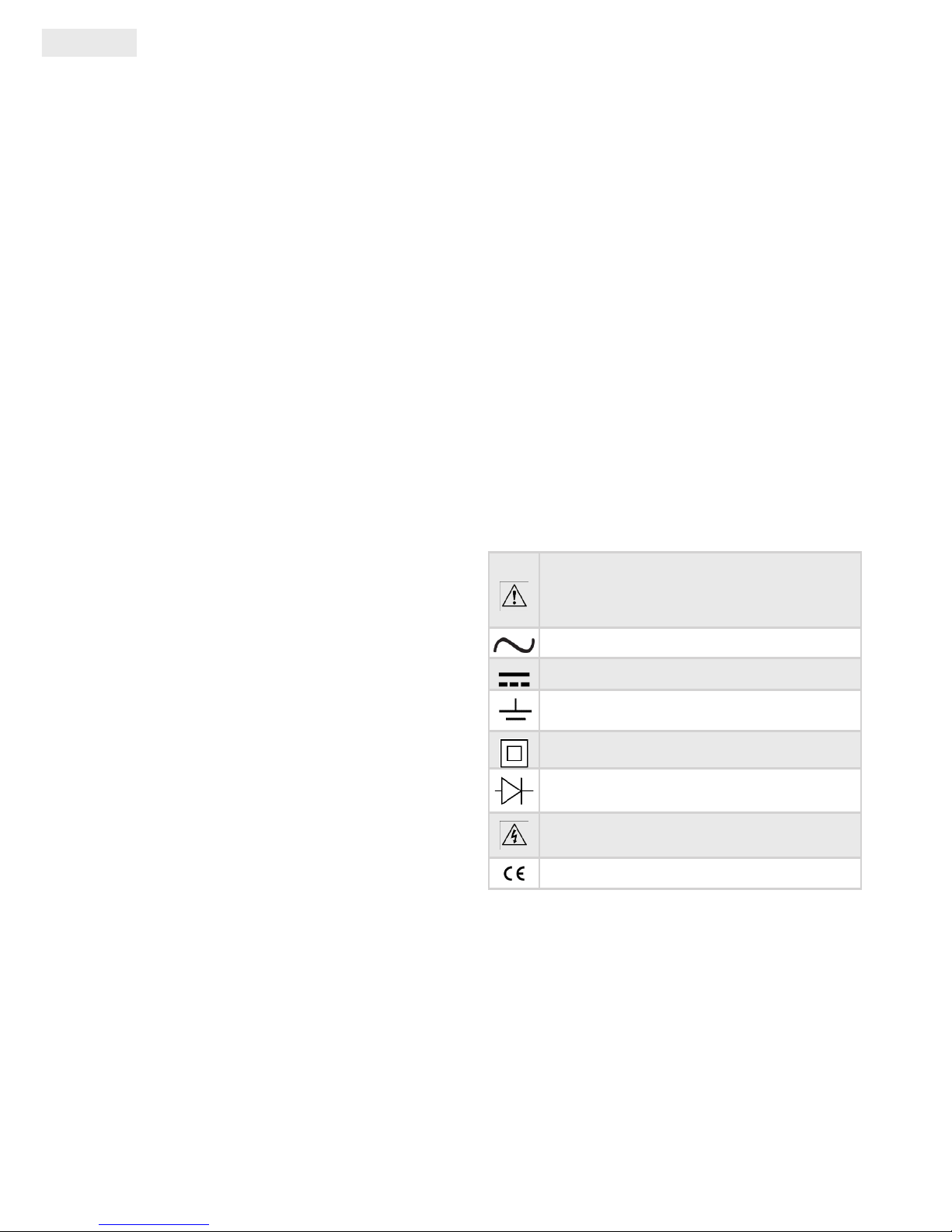
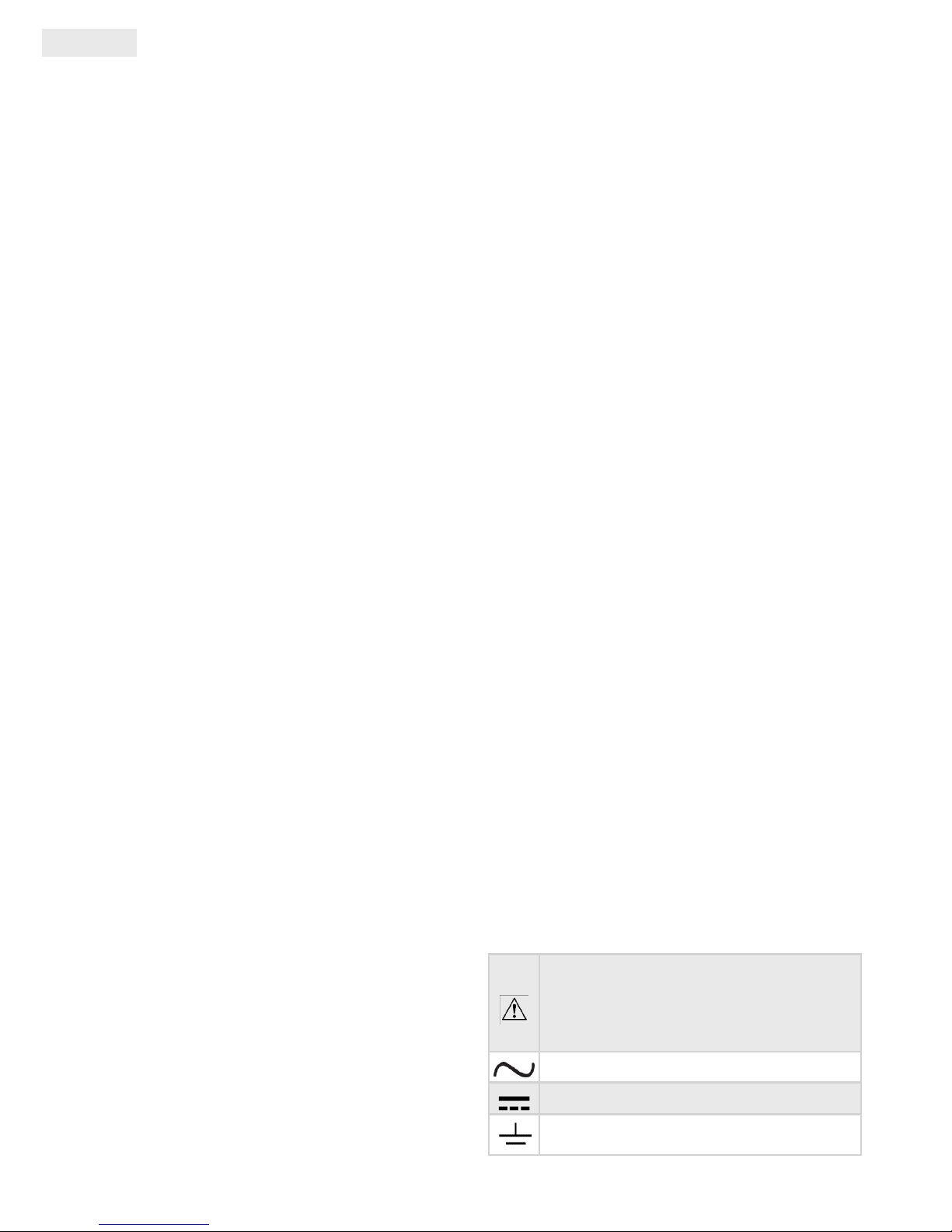
Symbols used on the device and in the
manual:
WARNING: Check the referring pages of
the manual! Improper use may lead to
device damage.
Alternate current (AC)
Direct current (DC)
Earthing
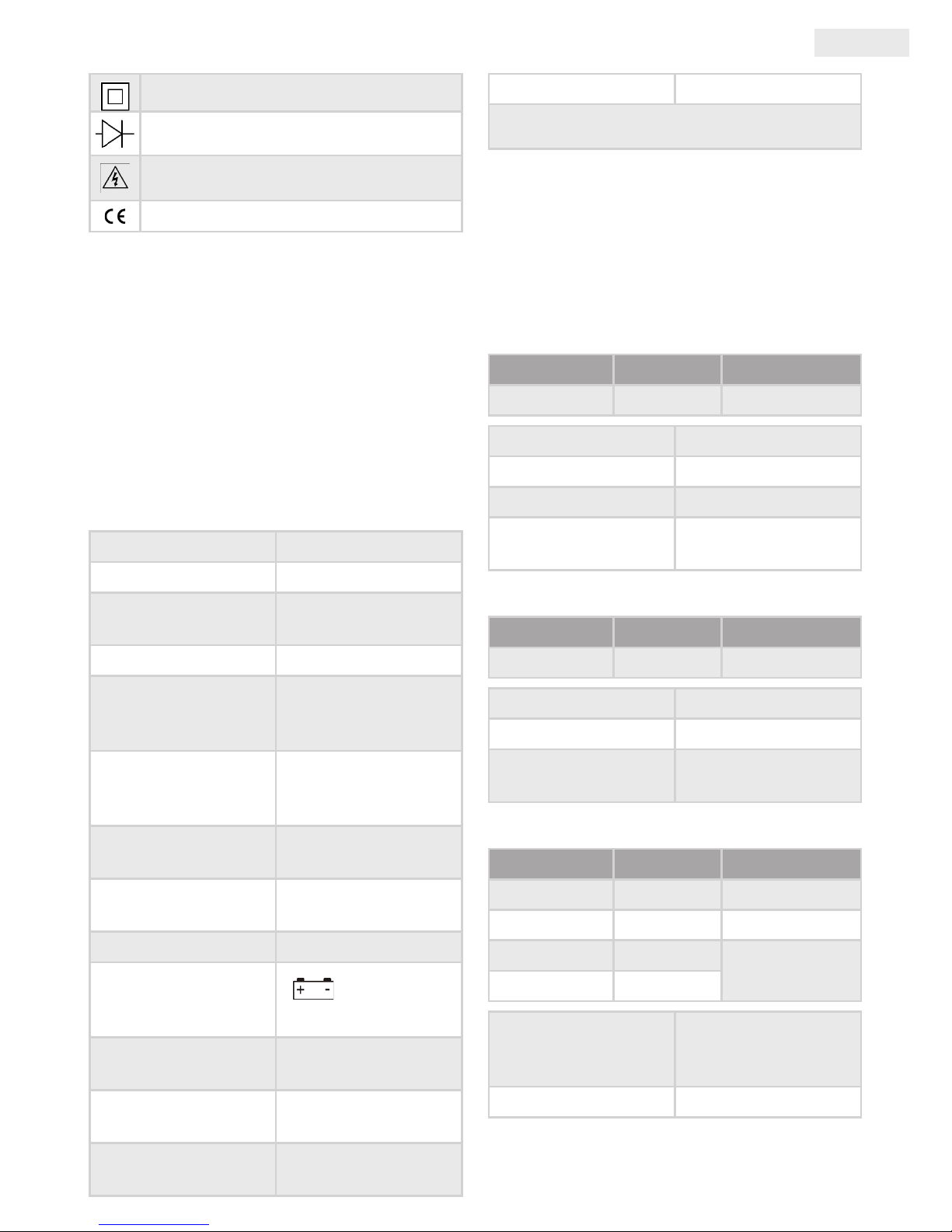
Double insulation
Diode
Dangerous voltage!
EU directives
description
This device is a compact digital clamp meter
with a 3 and ½ digit display for measuring AC
voltage, DC voltage, alternate current, resistance,
continuity and diode. It is easy to use and due to
its small size can always be around for a possible
measurement.
Page 3
User Manual
EN
general tecHnical
paraMeters
Display 3 and ½ digit, LCD
maximal
characteristic
1999
Overload display
„1” is displayed on the
screen
Sampling rate App. 3x per second
Error due to
incorrect placement
when reading
1 %
Sensor
Clamp shaped for AC
measuring
Distance between
clamps
27 mm
Max. measurable
conductor
Ø 25 mm
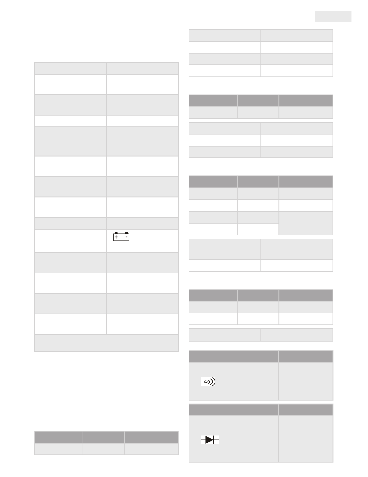
Battery 3x 3V, CR2032
Low battery power
”
„ icon on the
screen
Operating
temperature
0 ºC - 40 ºC, <75%
humidity
Storage
temperature
-20 ºC - 60 ºC, <85%
humidity
Size
151mm x 65mm x
34mm
Weight
app. 127g (with
battery)
Note: the conductor must be inside the closed area
between the clamps for proper measurement
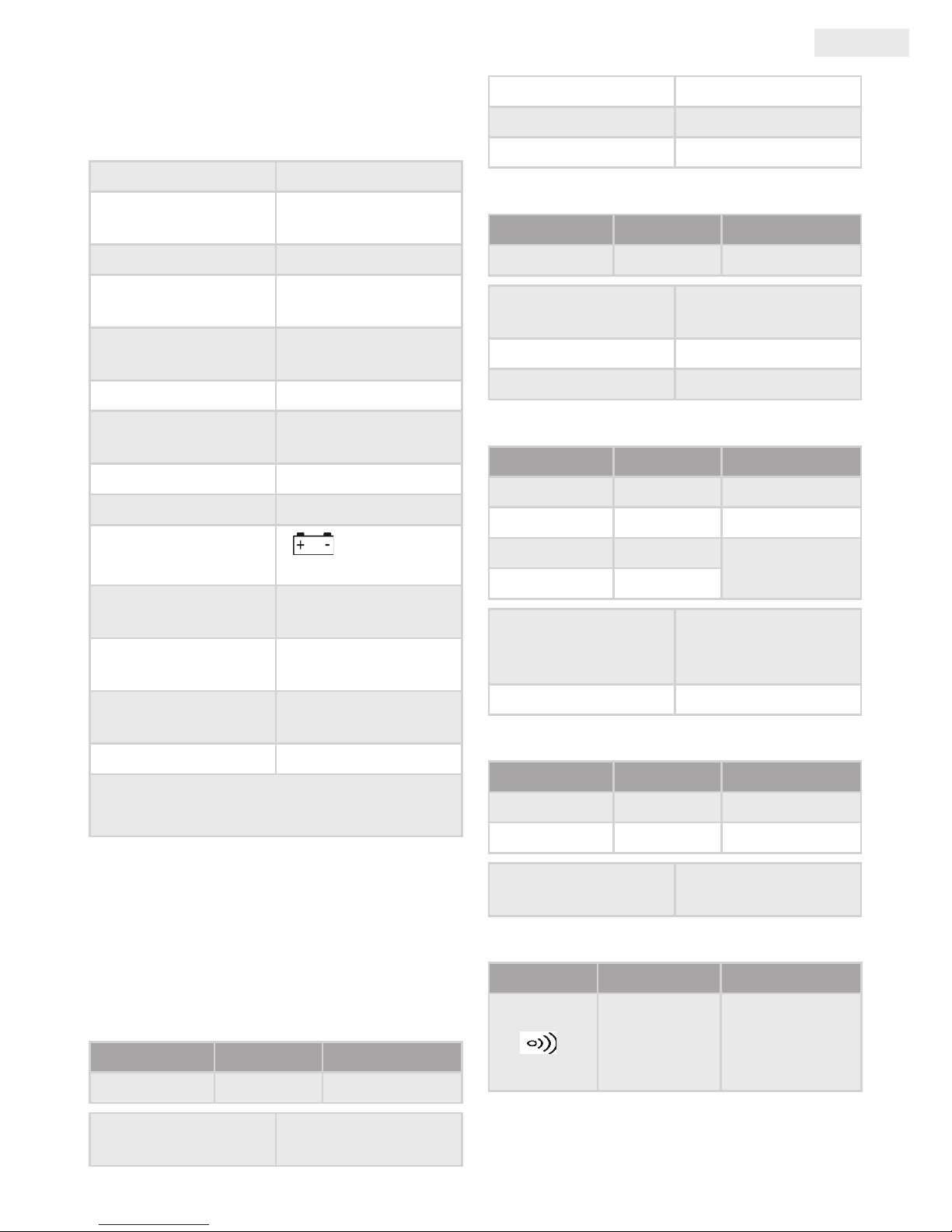
specification
Precision data were measured a year after
calibration under 18ºC-28ºC temperature, <75%
relative humidity. Format: ±(% measured value
+ value of digits)
AC voltage
Threshold Resolution Precision
600V 1V ±(1,2% + 3)
Overload protection DC 600V AC 600Vrms
Inward impedance 9MΩ
Frequency 40 Hz - 400 Hz
Max. inward voltage 600Vrms
DC voltage
Threshold Resolution Precision
600V 1V ±(1,2% + 3)
Overload protection DC 600V AC 600Vrms
Inward impedance 9MΩ
Max. inward voltage 600Vrms
AC current (alternate current)
Threshold Resolution Precision
2 A 1 mA ±(5,0% + 5)
20 A 10 mA ±(3,0% + 5)
200 A 100 mA
±(2,5% + 5)
400 A 1 A
Response time
average, calibrated to
the RMS sine waves
Frequency range 50 - 60 Hz
Resistance
Threshold Resolution Precision
2000 Ω 1 Ω ±(1,2% + 2)
200 kΩ 100 Ω ±(1,5% + 2)
Overload protection DC 250V AC 250Vrms
Diode or continuity test
Measuring Resolution Precision
1Ω
If the resistance
is ≤ 30 Ω
the device will
beep
Measuring Resolution Precision
1 mV
The
approximate
opening
voltage is
displayed
Page 4

EN
User Manual
Overload protection
250V DC or
AC rms
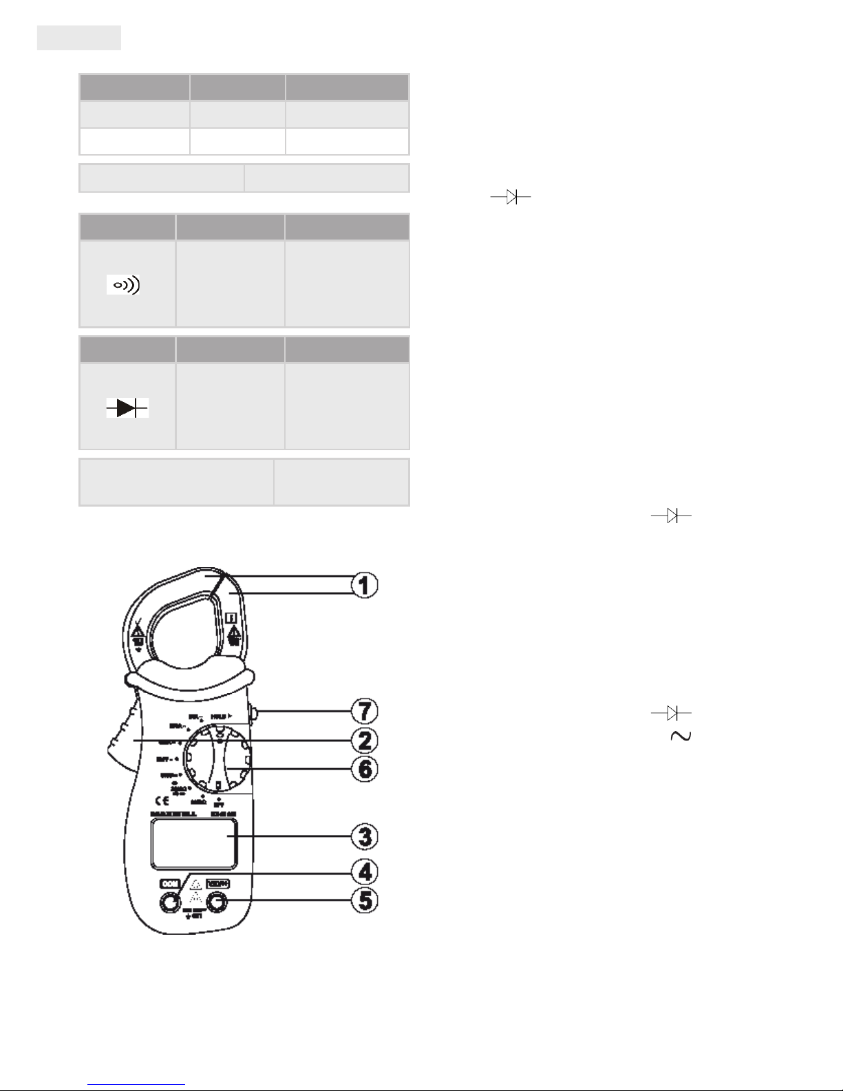
controls
1. Measuring clamps: For use with conductors.
To ensure proper measurement the conductor
needs to be in the closed area between the
clamps.
2. Clamp release button (trigger): To open and
close the clamps.
3. Display : 3 and ½ digit LCD, max.display:
1999
4. „COM” connector: For connectint the black
(negative) measuring wire.
5. „V Ω ” connector: For connecting the
red (positive) measuring wire..
6. Function selection (rotating) button: For
selecting the desired measuring function
and threshold, and turning the device on/o.
bekapcsolásához használhatjuk.
7. „HOLD” button: After pressing the button
the measured value will be held on the screen
with the "HOLD" text displayed. To turn o this
mode press the button again.
Using tHe claMp Meter
DC voltage measurement
• Connect the black measuring wire to the
"COM"connector and the red one to the „V Ω
” connector.
• Set the function selection button to the „600V
” position.
• Touch the measuring wires to the measured
source.
• The measured value is displayed on the screen,
along with the polarity of the red wire.
AC voltage measurement
• Connect the black measuring wire to the
"COM"connector, and the red one to the „V Ω
” connector.
• Set the function selection button to the „600V
” position.
• Touch the measuring wires to the measured
source.
• The measured value is displayed on the screen.
AC current measurement
• Set the function selection button to the
appropriate threshold for the measurement
• Pull the trigger to release the clamps and place
them over and around the conductor. Make
sure that the clamps are properly closed.
• The measured value is displayed on the screen.
Note:
• Only measure one conductor at a time!
• The phase and null sine values in one conductor cancel
each other out, the measured value will be 0!
• Do not touch the conductor by hand, not even if you are
sure that it is properly insulated.
Resistance measurement
• Connect the black measuring wire to the
"COM"connector, and the red one to the „V Ω
” connector.
• Set the function selection button to „2000 Ω”
or „200kΩ” position, based on the measured
object.
• Touch the measuring wires to the measured
source.
• The measured value is displayed on the screen.
Note: Before measuring resistance make sure that the
source is not under power and all high capacity capacitors
are discharged.
Page 5
User Manual
EN
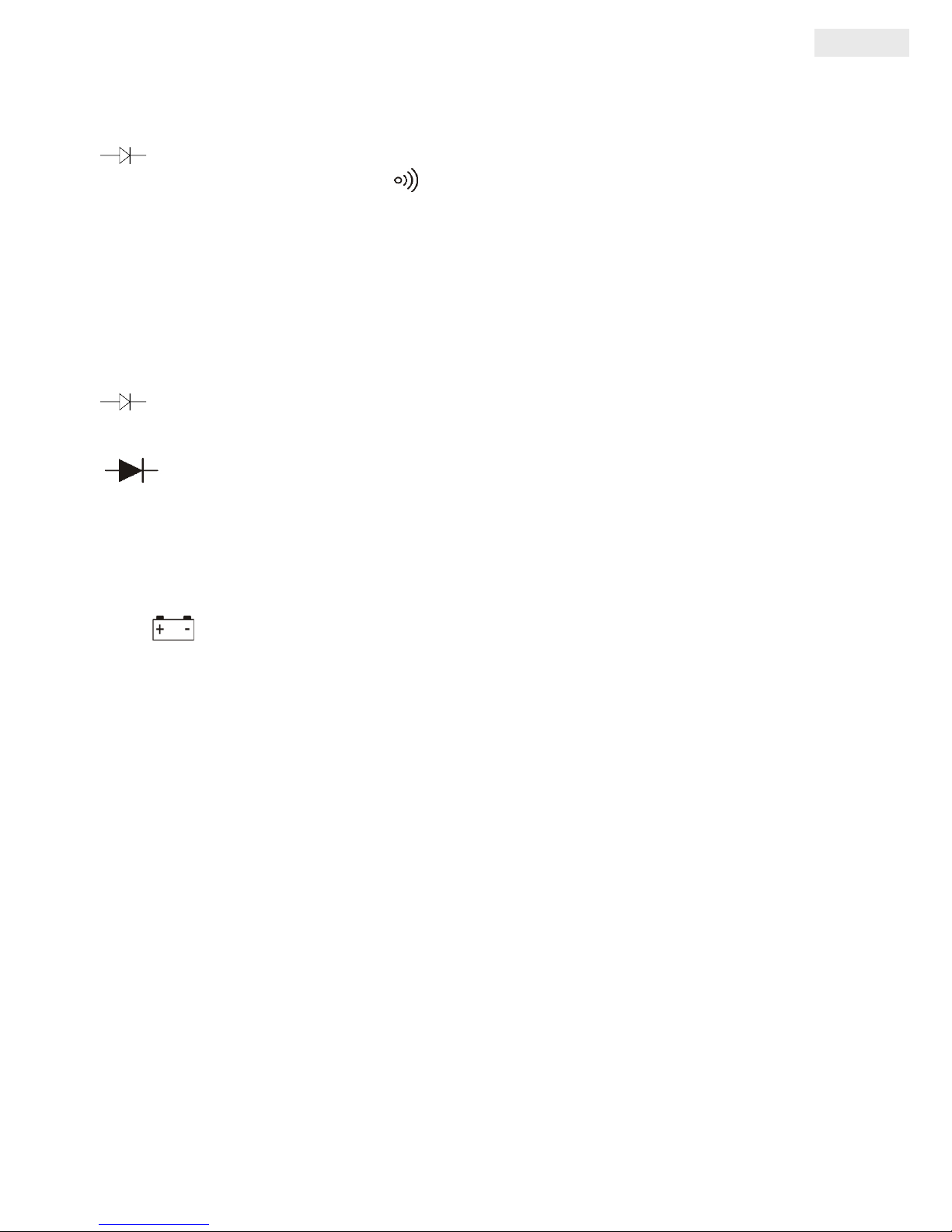
Continuity test
• Connect the black measuring wire to the
"COM"connector and the red one to the „V Ω
” connector.
• Set the function selection button to „ ”
position.
• Touch the measuring wires serially to the
measured source.
• If the measured resistance is lower than 30Ω,
the device will beep.
Diode measurement
• Connect the black measuring wire to the
"COM"connector and the red one to the „V Ω
” connector. The polarity of the red wire
will be positive.
• Set the function selection button to the „
” position.
• Touch the red measuring wire to the anode of
the diode, and the black one to the cathode.
• The opening voltage of the diode is displayed.
The value is in mV-s.
Battery replacement
• If the „ ” symbol is displayed on the
screen, the battery power is running low. For
replacement remove the measuring wires from
the device and the clamps from a possibly
measured circuit. Turn the device o and
remove the screws from the battery container
lid. Replace the used batteries to those of the
same type and voltage (3 x 3V, CR2032) Pay
attention to the polarity of the batteries, the
"+" sign must be upwards. Replace the battery
container lid.
Maintenance
You can clean the connectors according to the
following:
• Make sure that the clamps are not connected
to a circuit or a measured object.
• Turn the device o and remove the measuring
wires.
• Shake out the possible dirt from the
connectors.
• Dip a cotton swab into isopropyl alchohol and
carefully wipe the connectors.
Regularly wipe the device with a wet cloth or a cloth with
gentle detergent. Do not use solvents or abrasives. Dirt on
the connectors may cause incorrect measuring results.
accessories
• 1 user manual
• 1 pair of measuring wires
Page 6
DE
Anwendungsinformation
sicHerHeitsinforMation
Dieses Messgerät entspricht die Vorschriften des
elektronischen standards IEC-61010 von CAT II.
600V.
WarnUngen
Um Stromschläge und eventuelle VErletzungen
zu vermeiden, befolgen Sie Anweisungen der
Bedienungsanleitung.:
• Das Gerät darf nicht benutzt werden wenn
es beschädigt ist. Bevor Anwendung soll die
Unversehrtheit der Hülle überprüft werden.
Beachten Sie die Isolierung der Anschlüsse.
• Überprüfen Sie, ob die Isolierungen der
Anschlüsse nicht mit Metall in Berührung
kommen. Falls die Messleitungen beschädigt
sind, sollen sie sofort ausgetauscht werden.
• Benutzen Sie das Gerät nicht, wenn es nicht
perfekt funktioniert. Wenn Sie Zweifel am
Betrieb des Geräts haben, bringen Sie es in
Service .
• Das Gert darf nicht in der Nähe von
brennbaren, expolisonsgefährlichen Gasen,
Dämpfe und Pulvern benutzt werden.
• Der gegebene höchste Messbereich darf nie
überschritten werden.
• Bevor Sie das Gerät verwenden, überprüfen
Sie den Betrieb der Greifzange auf einen
bekannten Stromkreis.
• Wenn Sie das Gerät reparieren, benutzen Sie
immer die Bestandteile, die vom Hersteller
empohlen werden.
• Seien Sie vorsichtig bei der Messung von
wechselnden 30V RMS, 42V Hochspannung
oder 60V Gleichspannung, da es Stromschlag
erregen kann.
• Falls Sie eine Ergenzungssonde benutzen,
beachten Sie, dass Ihre Finger immer hinter
dem metallischen Teil der Sonde, im isolierten
Bereich sein sollen.
• Die sekundäre Messleitung (schwarz)
soll zuerst, dann die primäre (rote) zum
messenden Gegenstand, Stromkreis
verbunden werden. Nach der Messung soll
zuerst die primäre, dann die sekundäre
Messleitung vom Stromkreis abgelöst werden.
• Die Messleitungen sollen immer entfernt
werden, bevor Sie die Deckplatte des
Batteriehalters önen.
• Das Gerät darf nie benutzt werden, wenn die
Deckplatte des Batteriehalters geönet ist
oder die Gehäuse beschädigt ist.
• Um das falsche Wert der Messung und die
eventuelle Personal-Verletzungen vermeiden
zu können, soll die Batterie ehestens getauscht
werden, wenn Sie den Symbol auf dem Display
erblicken.
• Wenn Sie den Schoss des Messgeräts
benutzen, entfernen Sie die Messleitungen!
• Die Anker sollen aus dem Stromkreis entfernt
werden, bevor Sie die Deckplatte önen.
• Bei CAT II. Messungen (Schwachstrom; Klein,-
und Haushaltsgeräte) benutzen Sie nicht die
höhere Messbereiche wie CAT III. oder CAT
IV.-. Das könnte zur Beschädigung des Geräts
führen.
Achtung!
Um die Beschädigung des Messgeräts
vermeiden zu können, folgen Sie die folgende
Vorschrifte:
• Bevor Widerstandsmessung, Diode,- oder
Kontinuitätstest soll das Gerät ausgeschaltet
und die Kondensatoren mit großer Kapazität
entladet werden.
• Die Messungen sollen immer im gegebenen
Messbereich geführt werden. Wenn Sie das
Wert vorher nicht wissen, fangen Sie mit der
Messung im höchsten Messbereich an und
bewegen Sie daher rückwerts.
• Bei der Anwendung des Funktionsschalters
darf das Gerät nicht zum messenden
Stromkreis oder zu anderen Gegenstände
verbunden werden.
Angewendete Symbole am Messgerät und in
der Bedienungsanleitung:
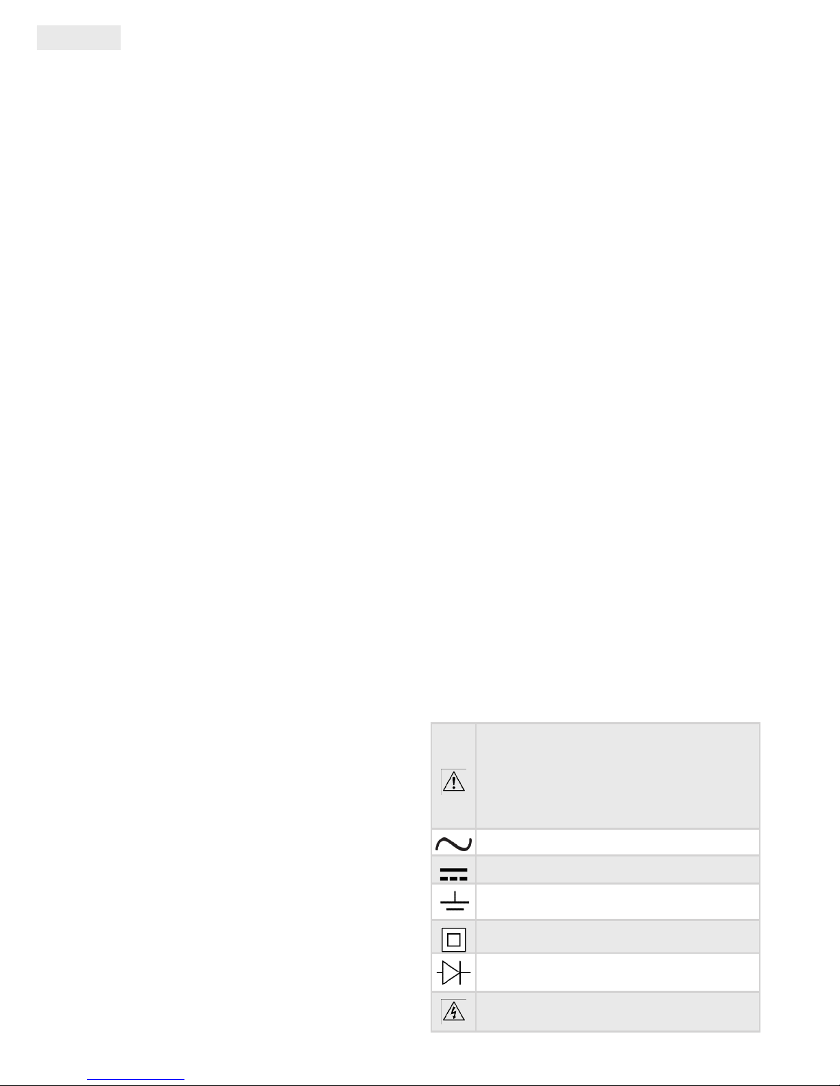
Warnung: Lesen Sie vorsichtig die
Bedienungsanleitung! Die falsche
Verwendung kann zur Beschädigung
des Geräts führen!
Wechselstrom (AC)
Gleichsstrom (DC)
Erdung
Page 7
Anwendungsinformation
DE
Doppel-Isolierung
Diode
Gerfährliches Spannungswert!!
Übereinstimmung mit EU-Richtlinien
BescHreiBUng
Diese Greifznage ist ein kompaktes DigitalMessgerät mit einem 3 ½ digit Display zur
Messung von AC Spannung, DC Spannung,
Wechsselstrom, Widerstand, Kontinuität,- und
Diodentest. Es ist einfach zu behandeln und ist
wegen seiner kleinen Format immer anhanden.
allgeMiene tecHniscHe
daten
Display 3 ½ digit, LCD
max. Charakteristik 1999
Anzeige der
Überlastung
„1” jelenik meg az
LCD-n
Musterentnahme ca. 3x 1 Sec
beim Lesen von
Fehler wegen
ungenauer Lage
1 %
Sensor
Schlossförmiger
Sensor zur AC
Messung
Rauminhalt der
Wangen
27 mm
Max. messbare
Leitung
Ø 25 mm
Batterie 3V, CR2032, 3 Stücke
Niedrige
Versorgungsspannung
”
„ auf dem
Display
Betriebstemperatur
0 ºC - 40 ºC, <75%
Luftfeuchtigkeit
Lagertemperatur
-20 ºC - 60 ºC, <85%
Luftfeuchtigkeit
Größe
151mm x 65mm x
34mm
Gewicht ca. 127g (mit Batterie)
Anmerkung: die Leitung soll wegen der genauen
Messung zwischen den Wangen der Greifzange sein.
spezifikation
A pontosság mérése a kalibráció után egy évvel,
18ºC-28ºC közötti hőmérsékleten, <75% relatív
páratartalom esetén lettek mérve. Formátum:
±(% mért érték + digitek értéke)
AC Spannung
Messbereich Auösung Präzision
600V 1V ±(1,2% + 3)
Überlastungsschutz DC 600V AC 600Vrms
Eingangsimpedanz 9MΩ
Frequenz 40 Hz - 400 Hz
Max.
Eingangsspannung
600Vrms
DC Spannung
Messbereich Auösung Präzison
600V 1V ±(1,2% + 3)
Überlastungsschutz DC 600V AC 600Vrms
Eingangsimpedanz 9MΩ
Max.
Eingangsspannung
600Vrms
AC Strom (Wechselstrom)
Messbereich Auösung Präzision
2 A 1 mA ±(5,0% + 5)
20 A 10 mA ±(3,0% + 5)
200 A 100 mA
±(2,5% + 5)
400 A 1 A
Zeitdauer der
Antwort
durchschnittlich, auf
die Sinuswelle von
RMS kalibriert
Frequenzbereich 50 - 60 Hz
Ellenállás
Page 8

DE
Anwendungsinformation
Messbereich Auösung Präzision
2000 Ω 1 Ω ±(1,2% + 2)
200 kΩ 100 Ω ±(1,5% + 2)
Überlastungsschutz DC 250V AC 250Vrms
Diode,- oder Kontinuitätstest
Messung Auösung Präzision
1Ω
Wenn der
Widerstand ≤
30 Ω werden
Sie einen
Pton hören
Messung Auösung Präzision
1 mV
ca. Önungs-
spannung ist
vom Display
ablesbar
Überlastungsschutz
250V DC oder
AC rms
BeHandlUngsorgane
1. Zangenanker: werden zur Messung der
Leitungen benutzt. Um ein genaues Wert zu
bekommen, sollen die Leitungen zwishcen
Wangen sein.
2. Ablösetaste der Greifzange (Abzug):
A mérőpofák nyitásához illetve zárásához
használhatjuk.
3. Kijelző: 3 és ½ digites LCD, max. kijelzés:
1999
4. „COM” aljzat: A fekete (negatív) mérőzsinór
csatlakoztatásához.
5. „V Ω
” aljzat: A piros (pozitív)
mérőzsinór csatlakoztatásához.
6. Funkcióválasztó- (forgató-) gomb: A kíván
mérési funkció és tartomány kiválásztásához,
illetve a lakatfogó ki/bekapcsolásához
használhatjuk.
7. „HOLD” gomb: A gomb megnyomása
után az éppen mért érték a kijelzőn rögzítve
marad, eközben a „HOLD” felirat olvasható a
kijelzőn. Az mód kikapcsolásához nyomjuk meg
mégegyszer a gombot.
verWendUng der
greifzange
Messung von DC Spannung
• Verbinden Sie die schwarze Messleitung in
die „COM” Buchse, die rote in die „V Ω ”
Buchse.
• Stellen Sie die Drehtaste in die „600V" Position.
• Berühren Sie die messende Quelle mit den
Messleitungen.
• Sowohl das gemessene Wert, als auch die
Polarität der roten Leitung ist vom Display
abzulesen.
Messung von AC Spannung
• Verbinden Sie die schwarze Messleitung in
die „COM” Buchse, die rote in die „V Ω ”
Buchse.
• Stellen Sie die Drehtaste in die „600V ”
Position.
• Berühren Sie die messende Quelle mit den
Messleitungen.
• Das gemessene Wert ist vom Display
abzulesen.
Messung von AC Strom
• Stellen Sie den Funktionsschalter in die
adäquate Position.
• Drücken Sie den Abzug zur Entkopplung
Page 9

Anwendungsinformation
DE
der Ankern und erfassen Sie die Leitungen
zwischen die Ankern. Vergewissen Sie sich, ob
sich die Anker gut schliessen.
• Das gemessene Wert ist vom display
abzulesen.
Anmerkung:
• Zugleich darf nur eine Messung durchgeführt werden!
• Sinuswerte von Phase und Null , die in der gleichen
Leitung laufen, lösen einander aus und das wert wird 0
sein.
• Berühren Sie nicht mit dem eigenen Hand die Leitung,
selbst wenn sie denken, dass es gut isoliert ist.
•
Widerstandsmessung
• Verbinden Sie die schwarze Messleitung in
die „COM” Buchse, die rote in die „V Ω ”
Buchse.
• Stellen Sie die Drehtaste in„2000 Ω” oder
„200kΩ” Position, abhängig von der Größe des
messenden Geräts.
• Berühren Sie das messende Gerät mit den
Messleitungen.
• Das gemessene Wert ist vom display
abzulesen.
Anmerkung: Vergewissen Sie sich bei
Widerstandsmessung ob die messende Quelle nicht an
keinen Stromkreis verbunden ist und alle Kondensatoren
von hoher Kapazität entladet sind.
Kontinuitätstest
• Verbinden Sie die schwarze Messleitung in
die „COM” Buchse, die rote in die „V Ω ”
Buchse.
• Stellen Sie die drehtaste in „ ” Position.
• Verbinden Sie die messende Quelle seriell mit
den Messleitungen.
• Wenn der gemessene Widerstand kleiner als
30Ω ist, werden Sie einen Pton hören.
Diodentest
• Verbinden Sie die schwarze Messleitung in
die „COM” Buchse, die rote in die „V Ω
”
Buchse. Die Polarität der roten Messleitung ist
postiv.
• Stellen Sie die Drehtaste in „ ”
Position.
• Berühren Sie die Anode der Diode mit der
roten Messleitung, den Ausführung der
Kathode mit der schwarzen Messleitung. .
• Lesen Sie die Önungsspannung der Diode.
Das Wert ist in mV angegeben.
Batterieaustausch
• Auf dem Display erscheint folgendes
Symbol „ ” ,es bedeutet, dass die
Batterien ausgetauscht werden müssen. Die
Messleitungen müssen aus dem Gerät und
die Messklammen vom Stromkreis entfernt
werden. Das Gerät soll ausgeschaltet
werden. Schrauben Sie den Batteriehalter
aus. Tauschen Sie die Batterien aus (gleiche
Spannung und Größe 3 Stk 3V, CR2032)
Beachten Sie die Polarität, die Batterie soll
mit „+” Zeichen hinauf sein. Legen Sie den
Batteriehalter zurück.
Instandhalten
Sie können die Buchsen nach folgender Weise
reinigen:
• Seien Sie sicher, ob die Messklammen mit
Stromkreise oder messene Geräte nicht in
Verbindung stehen.
• Schalten Sie das Gerät aus und entfernen Sie
die Messleitungen.
• Entfernen Sie die eventuelle Verschmutzungen
aus der Buchse.
• Tauchen Sie ein Wattestäbchen in Isopropyl-
Alkohol und wischen Sie vorsichtitig die
Buchsen.
Das Gerät soll regelmäßig mit einem nassen oder mit
Reinigungsmittel bedeckten Tuch gereinigt werden.
Benutzen Sie kein Lösungsmittel oder Scheuernmittel.
Die Verschnutzung an den Buchsen kann falsche
Messergebnisse erzeugen.
zUBeHör
• 1 Bedienungsanleitung
• 1 Paar Messleitungen
Page 10
HU
Használati utasítás
Biztonsági inforMáció
Ez a multiméter megfelel a IEC-61010
elektronikai szabványnak CAT II. 600V.
Biztonsági
figyelMeztetések
Az esetleges áramütés és személyi sérülés
elkerülése érdekében kövesse a következő
utasításokat:
• Soha ne használja a műszert ha az sérült.
Használat előtt ellenőrizze a burkolat épségét.
Fordítson különös gyelmet a csatlakozók
érintkezésének szigetelésére.
• Ellenőrizze a mérőzsinórok szigetelését vagy
hogy nem érintkeznek-e fémmel. Cserélje ki a
mérőzsinórokat ha azok sérültek.
• Ne használja a műszert ha az a normálistól
eltérően működik. Ha kétségei vannak a
működéssel kapcsolatban vigye szervízbe.
• Ne használja a készüléket gyúlékony,
robbanásveszélyes gázok, gőzök és porok
környezetében.
• Soha ne mérjünk a megengedett legnagyobb
méréshatárnál nagyobbat.
• Használat előtt ellenőrizze a lakatfogó
működését egy ismert áramkörön.
• Ha a készüléket javítja, mindig használja az
gyártó által javasolt alkatrészeket.
• Fokozott óvatossággal mérjen 30V váltakozó
RMS, 42V csúcs vagy 60V egyenfeszültség
esetén, mert könnyedén súlyos áramütés
érheti.
• Ha valamilyen kiegészítő szondát használ,
gyeljen arra, hogy ujjai mérés közben a
szonda fém része mögött, a szigetelt területen
helyezkedjenek el.
• A másodlagos mérőzsinórt (fekete)
csatlakoztassa először a mérendő tárgyhoz,
áramkörhöz, majd az elsődlegest (piros). A
mérés befejezésekor pedig az elsődlegest
válassza le először az áramkörről, majd a
másodlagost.
• Mindig távolítsa el a mérőzsinórokat, mielőtt
felnyitja az elemtartó fedelet.
• Soha ne használja a műszert nyitott elemtartó
fedéllel, vagy sérült házzal.
• A hibás mérési eredmény, illetve az esetleges
személyi sérülések elkerülése végett („szivárgó
áram”) cserélje minél hamarabb az elemet a
készülékben ha az azt jelző ikon megjelenik a
kijelzőn.
• A műszer lakat részének használatakor a
mérőzsinórokat távolítsuk el.
• Mielőtt felnyitjuk az elemtartó fedelet akkor
távolítsuk el a lakatfogó mérőpofáit az
áramkörből.
• CAT II.-nél (gyengeáramú készülékek,
áramkörök; háztartási-, egyszerű eszközök)
ne mérjünk magasabb kategórában pl. CAT
III. vagy CAT IV.-ben. Ugyanis az a készülék
károsodásához illetve súlyos áramütéshez
vezethet.
FIGYELEM!
A készülékben keletkező károk elkerülése
érdekében mindig tartsuk be a következő
utasításokat:
• Kapcsoljuk ki az áramforrást illetve süssük ki a
nagy kapacitású kondenzátorokat ellenállás,
dióda vagy folytonosság mérése előtt.
• Mindig a megfelelő mérési tartományban
mérjünk. ha nem ismerjük a mért értéket
kezdjünk a legnagyobb mérési tartományban
és úgy haladjunk visszafelé.
• A funkció választó gomb eltekerésekor ne
csatlakozzunk a mérendő áramkörhöz illetve
tárgyhoz.
A készüléken és a leírásban használatos szimbólumok:
FIGYELMEZTETÉS: Nézze meg a
használati útmutató erre vonatkozó
utasításait! A nem megfelelő használat
a készülék meghibásodásához
vezethet!
Váltóáram (AC)
Egyenáram (DC)
Föld
Dupla szigetelés
Dióda
Veszélyes feszültégi érték!!
Page 11

Használati utasítás
HU
EU irányelvek
leírás
Ez a készülék egy kompakt digitális lakatfogó,
3 és ½ digites kijelzővel AC feszültség, DC
feszültség, váltóáram, ellenállás, folytonosság
és dióda méréséhez. Könnyen kezelhető és
kis mérete miatt állandóan kéznél lehet egy
esetleges méréskor.
általános tecHnikai
paraMéterek
Kijelző 3 és ½ digit, LCD
maximális
karakterisztika
1999
Túlterhelés kijelzése
„1” jelenik meg az
LCD-n
Mintavételezés
Kb. 3x egy másodperc
alatt
Pontatlan
elhelyezésből
eredendő hiba
olvasáskor
1 %
Érzékelő
Lakat formájú AC
méréshez
Pofák befogadó
szélessége
27 mm
Max. mérhető
vezető
Ø 25 mm
Elem 3V, CR2032, 3db
Alacsony tápellátás
jelzés
”
„ jel a kijelzőn
Működési
hőmérésklet
0 ºC - 40 ºC, <75%
páratartalom
Tárolási
hőmérséklet
-20 ºC - 60 ºC, <85%
páratartalom
Méret
151mm x 65mm x
34mm
Súly
kb. 127g (elemmel
együtt)
Megjegyzés: a vezetőnek a lakatfogó mérőpofái közé
zárt területen kell elhelyezkednie a pontos mérés
érdekében
specifikáció
A pontosság mérése a kalibráció után egy évvel,
18ºC-28ºC közötti hőmérsékleten, <75% relatív
páratartalom esetén lettek mérve. Formátum:
±(% mért érték + digitek értéke)
AC feszültség
Méréshatár Felbontás Pontosság
600V 1V ±(1,2% + 3)
Túlterhelés védelem DC 600V AC 600Vrms
Bemenő impedancia 9MΩ
Frekvencia 40 Hz - 400 Hz
Maximális bemenő
feszültség
600Vrms
DC feszültség
Méréshatár Felbontás Pontosság
600V 1V ±(1,2% + 3)
Túlterhelés védelem DC 600V AC 600Vrms
Bemenő impedancia 9MΩ
Maximális bemenő
feszültség
600Vrms
AC áram (váltóáram)
Méréshatár Felbontás Pontosság
2 A 1 mA ±(5,0% + 5)
20 A 10 mA ±(3,0% + 5)
200 A 100 mA
±(2,5% + 5)
400 A 1 A
Válaszidő
átlagos, az RMS
szinuszhullámára
kalibrálva
Frekvencia tartomány 50 - 60 Hz
Ellenállás
Page 12
HU
Használati utasítás
Méréshatár Felbontás Pontosság
2000 Ω 1 Ω ±(1,2% + 2)
200 kΩ 100 Ω ±(1,5% + 2)
Túlterhelés védelem DC 250V AC 250Vrms
Dióda vagy folytonossági teszt
Mérés Felbontás Pontosság
1Ω
Ha az ellenállás
≤ 30 Ω
sípoló hangot
fogunk hallani
Mérés Felbontás Pontosság
1 mV
A körülbelüli
nyitófeszültség
olvasható le a
kijelzőn.
Túlterhelés védelem
250V DC vagy
AC rms
kezelőszervek
1. Mérőpofák: Vezetők mérésére használhatjuk.
A pontos mérési eredmény eléréséhez a
vezetőnek a pofák közt közre zárt területen kell
elhelyezkednie.
2. Lakatfogó kioldó gomb (ravasz): A
mérőpofák nyitásához illetve zárásához
használhatjuk.
3. Kijelző: 3 és ½ digites LCD, max. kijelzés:
1999
4. „COM” aljzat: A fekete (negatív) mérőzsinór
csatlakoztatásához.
5. „V Ω
” aljzat: A piros (pozitív)
mérőzsinór csatlakoztatásához.
6. Funkcióválasztó- (forgató-) gomb: A kíván
mérési funkció és tartomány kiválásztásához,
illetve a lakatfogó ki/bekapcsolásához
használhatjuk.
7. „HOLD” gomb: A gomb megnyomása
után az éppen mért érték a kijelzőn rögzítve
marad, eközben a „HOLD” felirat olvasható a
kijelzőn. Az mód kikapcsolásához nyomjuk meg
mégegyszer a gombot.
a lakatfogó Használata
DC feszültség mérése
• Helyezzük a fekete mérőzsinórt a „COM”
aljzatba, a pirosat pedig a „V Ω ” aljzatba.
• Állítsuk a forgatógombot a „600V ”
pozícióba.
• Érintsük a mérőzsinórokat a mérendő
forráshoz.
• A mért érték a kijelzőn olvasható, a piros
vezeték polaritásával együtt.
AC feszültség mérése
• Helyezzük a fekete mérőzsinórt a „COM”
aljzatba, a pirosat pedig a „V Ω ” aljzatba.
• Állítsuk a forgatógombot a „600V ”
pozícióba.
• Érintsük a mérőzsinórokat a mérendő
forráshoz.
• A mért érték a kijelzőn olvasható.
AC áram mérése
• Állítsuk a fukcióválasztógombot a mérésnek
megfelelő tartományba.
• Nyomjuk be a ravaszt a pofák kioldásához
majd fogjuk be a vezetőt a közre zárt területre.
Bizonyosodjunk meg arról, hogy a pofák jól
visszazáródtak.
• A mért érték a kijelzőn olvasható.
Megjegyzés:
• Egyszerre egy vezetőt mérjünk!
• Az egy vezetékben futó fázis és nulla szinusz értékei
Page 13
Használati utasítás
HU
kioltják egymást a mért érték 0 lesz!
• Ne érjünk a mért vezetőhöz kézzel, még akkor sem ha
biztosak vagyunk abban hogy az tökéletesen szigetelt.
•
Ellenállás mérése
• Helyezzük a fekete mérőzsinórt a „COM”
aljzatba, a pirosat pedig a „V Ω ” aljzatba.
• Állítsuk a forgatógombot a „2000 Ω” vagy
„200kΩ” pozícióba, a mérendő tárgy
nagyságától függően.
• Érintsük a mérőzsinórokat a mérendő
forráshoz.
• A mért érték a kijelzőn olvasható.
Megjegyzés: Ellenállás mérés előtt bizonyosodjuk
meg arról hogy a mért forrás nincs csatlakoztatva
semmilyen áramforráshoz, és minden nagyteljesítményű
kondenzátor ki van sütve.
Folytonossági teszt
• Helyezzük a fekete mérőzsinórt a „COM”
aljzatba, a pirosat pedig a „V Ω ” aljzatba.
• Állítsuk a forgatógombot „ ” pozicióba.
• Érintsük a mérőzsinórokat sorosan a tesztelt
forráshoz.
• Ha a mért ellenállás kisebb mint 30Ω, a
készülék sípoló hangot fog hallatni.
Diódamérés
• Helyezzük a fekete mérőzsinórt a „COM”
aljzatba, a pirosat pedig a „V Ω ” aljzatba.
A piros merőzsinór polaritása pozitív.
• Állítsuk a forgatógombot „ ” pozícióba.
• Érintsük a piros mérőzsinórt a dióda
anódjához, a feketét pedig a katód
kivezetéséhez.
• Olvassuk le a dióda nyitófeszültségét. Az érték
mV-ban van megadva.
Elemcsere
• Ha a kijelzőn megjelenik a „ ”
szimbólum, azt jelenti a készülékben lévő
elem feszültsége alacsony. A cseréhez
távolítsuk el a mérőzsinórokat a készülékből
és a mérőpofákat egy esetlegesen mért
áramkörből. Kapcsoljuk ki a készüléket.
majd csavarozzuk ki az elemtartó fedelet.
Az elhasználódott elemeket cseréljük ki
ugyanolyan feszültségűre és méretűre. (3 db
3V, CR2032) Figyeljünk a polaritásra, az elem
„+” jelzéssel felfelé helyezkedjen el. Ilessze
vissza az elemtartó fedelet.
Karbantartás
Az aljzatokat a következőképpen tisztíthatja:
• Bizonyosodjon meg hogy a mérőpofák nem
csatlakoznak áramkörbe vagy mért tárgyhoz.
• Kapcsolja ki a készüléket és távolítsa el a
mérőzsinórokat.
• Rázza ki az esetleges szennyeződéseket az
aljzatból.
• Mártson bele isopropyl alkoholba pl. egy
fültisztító pálcikát és óvatosan törölje körül az
aljzatokat.
Rendszeresen törölje meg a készüléket egy nedves
ronggyal, vagy gyenge mosószeres ruhával. Ne használjon
oldószert vagy súrolószert. A szennyeződés az aljzatokon
okozhat hibás mérési eredményeket.
tartozékok
• 1 db felhasználói kézikönyv
• 1 pár mérőzsinór
Page 14

RO
Manual de utilizare
inforMaţii de sigUranţă
Acest multimetru îndeplineşte standardul
electronic IEC-61010 CAT II. 600V.
avertisMent
de
sigUranţă
În scopul de a evita şocul electric şi vătămarea
corporală posibilă urmaţi instrucţiunile:
• Nu utilizaţi niciodată instrumentul dacă
acesta este deteriorat. Înainte de utilizare,
vericaţi integritatea carcasei. Acordaţi o
atenţie deosebită, la izolarea contactelor
conectoarelor.
• Vericaţi izolaţia cablurilor de testare, sau să
nu aibă contact cu metale. Înlocuiţi cablurile
de testare dacă acestea sunt deteriorate.
• Nu utilizaţi instrumentul în cazul în care
funcţionează diferit faţă de normal. Dacă
aveţi dubii în ceea ce priveşte funcţionarea
instrumentului duceţi-l la depanare.
• Nu folosiţi aparatul în mediu gazos, vaporos
inamabil şi exploziv, aburi sau praf.
• Niciodată nu măsuraţi valori mai mari decât vă
permite domeniul de măsurat maxim.
• Înainte de utilizare, vericaţi funcţionarea
cleştelui într-un circuit bine cunoscut.
• Când depanaţi aparatul, întotdeauna folosiţi
piese recomandate de producător.
• Măsuraţi cu mare prudenţă în caz de 30Vca
RMS, 42V de vârf sau 60Vcc deoarece uşor
puteţi suferi şoc grav electric.
• În cazul în care folosiţi sondă din accesorii
suplimentare ţi atent ca degetele în timpul
măsurării să rămână în spatele părţii metalice
în zona izolată a sondei.
• Cablul de măsurat secundar (negru) să
conectaţi prima dată la obiectul, circuitul care
urmează să e măsurat abia după aceasta pe
cel primar (roşu). După terminarea măsurării
deconectaţi cablul primar din circuit şi apoi cel
secundar.
• Întotdeauna scoateţi cablurile de testare
înainte de a deschide capacul bateriei.
• Nu folosiţi niciodată instrumentul cu capacul
bateriei deschisă, sau carcasă avariată.
• Pentru înlăturarea erorii rezultatelor de
măsurare şi pentru evitarea oricărui vătămare
corporală ( "scurgere de curent"), cât mai
curând posibil înlocuiţi bateria din aparat
atunci când pictograma este aşată.
• Când folosiţi partea de cleşte al instrumentului
scoateţi cablurile de testare.
• Înainte de a scoate capacul bateriei scoateţi
din circuitul de măsurat fălcile cleştelui.
• La CAT II (dispozitive, circuite de joasă
tensiune; dispozitive de uz casnic, simple) nu
măsuraţi în categorie mai mare. De ex. CAT III.
sau CAT IV. Poate duce la şoc electric grav sau
deteriorarea echipamentului.
ATENŢIE!
Pentru evitarea deteriorării aparatului
întotdeauna păstraţi următoarele instrucţiuni:
• Opriţi sursa de alimentare respectiv descărcaţi
condensatorii de mare capacitate înainte de
măsurarea rezistenţei, a diodelor sau înainte
de măsurare de continuitate .
• Întotdeauna măsuraţi în domeniul de măsurat
corespunzător. În cazul în care nu cunoaştem
domeniul rezultatului începem măsurarea
în domeniul maxim şi aşa avansăm înapoi la
domeniul mai mic.
• În momentul rotirii butonului selector de
funcţii să nu conectaţi instrumentul la circuitul
sau obiectul ce va măsurat.
Simbolurile folosite pe aparat şi în această
descriere:
AVERTISMENT: Consultaţi instrucţiunile
manualului referitoare la asta! Utilizarea
necorespunzătoare a aparatului o
poate deteriora!
Curent alternativ(AC)
Curent continuu(DC)
Masă
Izolaţie dublă
Diodă
Valoare periculoasă de tensiune!!
Directive EU
Page 15

Manual de utilizare
RO
descriere
Acest aparat este un Cleşte de măsurat compact
digital, cu aşaj de 3 şi ½ cifre pentru măsurarea
următoarelor: tensiune AC, tensiune DC, curent
alternativ, rezistenţă, continuitate şi diode. Uşor
de utilizat şi datorită dimensiunilor mici poate
la îndemână întotdeauna dacă se iveşte o
măsurare.
paraMetrii teHnici
generale
Aşaj LCD cu 3 şi ½ cifre
Caracteristică
maximă
1999
Aşarea de
suprasarcină
Apare „1” pe LCD
Prelevare de probe Cca. 3 ori pe secundă
La citire eroarea
rezultată din
aşezare inexactă
1 %
Senzor
Formă de cleşte
pentru măsurarea
curentului AC
Capabilitatea lăţimii
fălcilor
27 mm
Conductorul maxim
măsurabil
Ø 25 mm
Baterie 3 buc 3V, CR2032
Semnalarea
tensiunii slabe a
bateriei
Semnul ”
„ pe
aşaj
Temperatura de
lucru
0 ºC - 40 ºC, umiditate
<75%
Temperatura de
depozitare
-20 ºC - 60 ºC,
umiditate <85%
Mărime
151mm x 65mm x
34mm
Greutate cca. 127g (cu baterii)
Notă: În vederea măsurării precise conductorul trebuie
să e situat în zona închisă de fălcile aparatului
specficaţii
Măsurarea preciziei după un an de la calibrare
la temperatura 18ºC-28ºC, unde umiditatea
relativă <75%. Format: ±(% valoarea măsurată +
valoare cifrelor)
Tensiune AC
Domeniu Rezoluţie Acurateţe
600V 1V ±(1,2% + 3)
Protecţie la
suprasarcină
DC 600V AC 600Vrms
Impedanţa de intrare 9MΩ
Frekvenţa 40 Hz - 400 Hz
Tensiune maximă de
intrare
600Vrms
Tensiune DC
Domeniu Rezoluţie Acurateţe
600V 1V ±(1,2% + 3)
Protecţie la
suprasarcină
DC 600V AC 600Vrms
Impedanţa de intrare 9MΩ
Tensiune maximă de
intrare
600Vrms
Curent AC (alternativ)
Domeniu Rezoluţie Acurateţe
2 A 1 mA ±(5,0% + 5)
20 A 10 mA ±(3,0% + 5)
200 A 100 mA
±(2,5% + 5)
400 A 1 A
Timp de răspuns
mediu, calibrat la
unda sinusoidală a
RMS
Domeniu de
frekvenţă
50 - 60 Hz
Rezistenţă
Domeniu Rezoluţie Acurateţe
2000 Ω 1 Ω ±(1,2% + 2)
Page 16

RO
Manual de utilizare
Domeniu Rezoluţie Acurateţe
200 kΩ 100 Ω ±(1,5% + 2)
Protecţie la
suprasarcină
DC 250V AC 250Vrms
Diodă sau test de continuitate
Măsurare Rezoluţie Acurateţe
1Ω
Semnal sonor
dacă rezistenţa
este ≤ 30 Ω
Măsurare Rezoluţie Acurateţe
1 mV
Tensiunea de
deschidere
aproximativă se
va aşa.
Protecţie la suprasarcină 250V DC AC rms
părţile de control
1. Fălci de măsurat: Se pot folosi pentru
măsurarea conductorilor. În scopul de a obţine
rezultate precise conductorul trebuie să e
situat în zona închisă de fălcile aparatului.
2. Buton de deblocare a cleştelui (piedică):
Putem folosi la deschiderea sau închiderea
fălcilor de măsurat.
3. Aşaj: LCD cu 3 şi ½ cifre, aşare max.: 1999
4. Banană „COM”: pentru conectarea cablului
de testare neagră (negativ).
5. Banană „V Ω
” : pentru conectarea
cablului de testare roşie (pozitiv).
6. Buton de selectare funcţii (rotativ): Pentru
selectarea funcţiei, domeniului de măsurare
respectiv pentru a activa/dezactiva cleştele de
măsurat.
7. Butonul „HOLD”: După apăsarea butonului
valoarea reală măsurată rămâne pe ecran xat,
în acest timp va aşat „HOLD” pe ecran. Pentru
dezactivare apăsaţi butonul din nou.
Utilizarea cleştelUi de
MăsUrat
Măsurarea tensiunii DC
• Aşezaţi cablul de testare neagră în banana
„COM” iar cel roşu în „V Ω ”.
• Aşezaţi butonul rotativ în poziţia „600V ”
• Atingeţi cablurile de testare la sursa ce trebuie
măsurat.
• Valoarea măsurată se va regăsi pe aşaj
împreună cu polaritatea cablului de testare
roşie.
Măsurarea tensiunii AC
• Aşezaţi cablul de testare neagră în banana
„COM” iar cel roşu în „V Ω ” .
• Aşezaţi butonul rotativ în poziţia „600V ”.
• Atingeţi cablurile de testare la sursa ce trebuie
măsurat.
• Valoarea măsurată se va regăsi pe aşaj
împreună cu polaritatea cablului de testare
roşie.
Măsurarea curentului AC
• Aşezaţi butonul selector de funcţii în domeniul
de măsurat corespunzător.
• Apăsaţi piedica pentru declanşarea fălcilor
apoi aşezaţi conductorul în zona închisă între
fălci. Asiguraţi-vă că fălcile s-au închis la loc
corect.
• Valoarea măsurată se poate citi pe aşaj.
Notă:
• Deodată doar un singur conductor să măsuraţi!
• Valorile sinusoidale ale fazei şi nul-ului se anulează
reciproc şi aşa valoarea măsurată va 0!
Page 17

Manual de utilizare
RO
• Nu atingeţi conductorul măsurat cu mâna, chiar dacă
sunteţi sigur că acesta este complet izolat.
Măsurarea rezistenţei
• Aşezaţi cablul de testare neagră în banana
„COM” iar cel roşu în „V Ω ” .
• Aşezaţi butonul rotativ în poziţia „2000 Ω” sau
„200kΩ” în funcţie de mărimea obiectului ce va
măsurat.
• Atingeţi cablurile de testare la sursa ce trebuie
măsurat.
• Valoarea măsurată se va regăsi pe aşaj.
Notă: Înainte de măsurare a rezistenţei asiguraţi-vă că
sursa măsurată nu este conectată la nici o sursă de curent,
precum şi toate condensatoarele de mare capacitate sunt
descărcate.
Test de continuitate
• Aşezaţi cablul de testare neagră în banana
„COM” iar cel roşu în „V Ω ” .
• Aşezaţi butonul rotativ în poziţia „ ”.
• Atingeţi cablurile de testare în serie cu sursa
testată.
• Dacă rezistenţa măsurată este mai mică de
30Ω, aparatul va scoate un semnal sonor.
Măsurare de diode
• Aşezaţi cablul de testare neagră în banana
„COM” iar cel roşu în „V Ω
” . Cablul
detestare roşie are polaritatea pozitivă.
• Aşezaţi butonul rotativ în poziţia„ ”.
• Atingeţi cablul de testare roşie la anodul
diodei iar cel negru la catod.
• Citiţi tensiunea de deschidere al diodei.
Valoarea este aşată în mV.
Schimbarea bateriilor
• Dacă pe aşaj apare simbolul „ ” atunci
tensiunea bateriilor din aparat este mică.
Pentru a le schimba îndepărtaţi cablurile de
testare din aparat şi fălcile din circuitul testat
dacă e cazul. Opriţi aparatul. Deşurubaţi
capacul bateriilor. Bateriile uzate schimbaţi cu
altele noi de acelaşi dimensiuni şi valori. (3 buc
3V, CR2032) Aveţi în vedere polaritatea „+” –ul
bateriilor se vor aşeza în sus. Aşezaţi la loc
capacul bateriilor.
Întreţinere
Bananele puteţi curăţa în felul următor:
• Asiguraţi-vă că fălcile de măsurat nu sunt
conectate în circuit sau la obiect în vederea
măsurării.
• Opriţi alimentarea şi scoateţi cablurile de
testare.
• Scuturaţi eventualele mizerii din banane.
• Îmbibaţi în alcool izopropilic. un tampon de
bumbac (cum ar beţişorul de curăţat urechi)
şi ştergeţi cu grijă în jurul bananelor.
Curăţaţi periodic aparatul cu o cârpă umedă. Puteţi
utiliza apă cu puţin detergent. Însă nu folosiţi detergenţi
puternici, solventi, detergenţi cu materiale abrazive!
Coroziunile la şe afectează rezultatele de măsurare.
accesorii
• 1 buc manual de utilizare
• 1 pereche cablu de testare
Page 18

SK
Uživateľská príručka
Bezpečnostná inforMácia
Tento multimeter je vhodný elektronickej norme
IEC-61010 CAT II. 600V.
Bezpečnostné
Upozornenia
Aby ste vyhli prípadnému úrazu elektrickým
prúdom a osobnému zraneniu, dajte pozor na
nasledovné inštrukcie:
• Nikdy nepoužívajte prístroj, ak je poškodený.
Pred používaním skontrolujte, či obal nie je
poškodený. Dajte pozor zvlášť na izoláciu
spojení konektorov.
• Skontrolujte izoláciu meracích šnúr, a čí nie sú
v kontakte s kovom. Vymeňte meracie šnúry v
prípade ich poškodenia.
• Nepoužívajte prístroj, ak ten nefunguje
normálne. Ak mate pochybnosti v súvislosti s
fungovaním prístroja, odnieste ho do servisu.
• Nepoužívajte zariadenie v blýzkosti horlavých,
výbušných plynov, pary a prášok.
• Nikdy nemerajme nad maximálne povolenou
hranicou merania.
• Pred používaním skontrolujte funkciu
zámkovú svorku na jednom poznanom prúde.
• Ak opravujete zariadenie, použite vždy
súčiastky navrhované výrobcou.
• V prípade 30V striedavého RMS, 42V hrot,
alebo 60V jednosmerného prúdu merajte
zvýšenou opatrnosťou, lebo to lahko môže
viesť k úrazu elektrickým prúdom.
• Ak používate nejakú doplnkovú sondu, dajte
pozor na to, aby vaše prsty pri meraní boli za
kovovou časšťou sondy, na izolovanej oblasťi.
• Najprv pripojte k predmetu merania a na prúd
sekundárnu meraciu šnúru (čierna), potom
primárnu šnúru (červená). Na konci merania
z prúdu najprv odpojte primárnu, až potom
sekundárnu.
• Vždy odstráňte meracie šnúry pred otvorením
pokrývky baterky.
• Nikdy nepoužívajte prístroj s otvorenou
pokrývkou alebo poškodeným krytom.
• Aby ste nemali chybný výsledok merania a
vyhli osobným zraneniam ( unikujúci prúd),
čím skôr vymeňte baterku v zariadení, ak na
monitore sa objaví ikona.
• Pri používaní zámkovej kliešte časti prístroja
odstráňme meracie šnúry.
• Pred otvorením pokrývky baterky, odstráňme
chlypsy zámkovej kliešte z prúdu.
• Pri CAT II. (gyengeáramú zariadenia, prúdy;
domáce-, jednoduché prostriedky) nemerajme
vo vyššej kategórii napr. CAT III. alebo CAT
IV.. môže to viesť k poškodeniu zariadenia a k
vážnemu úrazu elektrickým prúdom.
POZOR!
Aby ste vyhli poškodeniam zariadenia, vždy
dodržte nasledovné pokyny:
• Vypnime zdroj prúdu a vybime kondenzátory s
velkou kapacitou pred meraním napätie, diody
alebo kontinuity.
• Merajme vždy v vhodnej oblasti merania.
Ak nepoznáme hodnotu merania, meranie
začnime v najväčšej oblasti merania a tak
postupujme naspäť.
• Pri odtočení gombíku výber funkcie sa
nepripojme na prúdu alebo predmetu
merania.
Symboly používané na zariadení a v opisu:
UPOZORNENIE: pozrite si pokyny
v návode na použitie! Nevhodné
používanie môže viesť k poškodeniu
prístroja!
Striedavý prúd (AC)
Jednosmerný prúd (DC)
Uzemnenie
Dvojitá izolácia
Dióda
Nebezpečná hodnota napätia!!
Normy EU
opis
Tento zariadenie je kompaktné digitálné
zámkové kliešte s 3 a ½ digitovým monitorom.
Na meranie AC napätie, DC napätie, striedavý
prúd, napätie, kontinuita a diódy. Lahko sa s ním
zaobchádzať, vždy môže byť po ruke kvôli jeho
velkosti pri prípadnom meraní.
Page 19
Uživateľská príručka
SK
všeoBecné tecHnické
paraMetre
Monitor 3 a ½ digit, LCD
maximálna
karakteristika
1999
Displej prehriatiu „1” sa objaví na LCD
Vzor
Kb. 3x počas jednej
sekundy
Chyba vyjavený z
nepresnej čítanie
1 %
Senzor Zámka k meranie AC
Pripustená šírka
chopsy
27 mm
Max. meraný vodič Ø 25 mm
Baterka 3V, CR2032, 3 kusy
Nízke pohonné
jednotky
”
„ oznamka na
displej
Prevádzková
teplota
0 ºC - 40 ºC, <75%
vlhkosť páry
Skladovacia teplota
-20 ºC - 60 ºC, <85%
vlhkosť páry
Rozmery
151mm x 65mm x
34mm
Váha kb. 127g (s baterkou)
Poznámka Vodič musí byť umiestnený v uzavretom
priestore medzi chlapsom zamkovej klište na presné
meranie
špecifikácia
Meranie presnosti po roku kalibrácie,boli
merané v teplote medzi 18ºC-28ºC, <75% v
prípade relatívneho vlhkosti pary. Formát: ±(%
nameraná hodnota+ hodnota digitov)
napätie AC (striedavý prúd)
Kapacita Rozlíšenie Presnosť
600V 1V ±(1,2% + 3)
Ochrana proti
prehriatiu
DC 600V AC 600Vrms
Vstupná impedancia 9MΩ
Frekvencia 40 Hz - 400 Hz
Max. vstupné nepätie 600Vrms
DC napätie
Kapacita Rozlíšenie Presnosť
600V 1V ±(1,2% + 3)
Ochrana proti
prehriatiu
DC 600V AC 600Vrms
Vstupná impedancia 9MΩ
Max. vstupné nepätie 600Vrms
AC prúd
Kapacita Rozlíšenie Presnosť
2 A 1 mA ±(5,0% + 5)
20 A 10 mA ±(3,0% + 5)
200 A 100 mA
±(2,5% + 5)
400 A 1 A
Doba odozvy
obyčajná, RMS
kalibrovaný na vlny
sínusa
Frekvencia 50 - 60 Hz
Odpor
Kapacita Rozlíšenie Presnosť
2000 Ω 1 Ω ±(1,2% + 2)
200 kΩ 100 Ω ±(1,5% + 2)
Ochrana proti
prehriatiu
DC 250V AC 250Vrms
Dióda alebo kontinuita test
Meranie Rozlíšenie Presnosť
1Ω
Ak odpor je
≤ 30 Ω
Budete počuť
pípnutie
Page 20

SK
Uživateľská príručka
Meranie Rozlíšenie Presnosť
1 mV
Na displeji
ja načítané
vstupné
napätie
Ochrana proti prehriatiu
250V DC alebo
AC rms
Manažéry
1. Meracie chlapsy: na používanie meranie
vodičov. Na dosiahnutie presného výsledku
merania, vodič sa musí nachádzať na oblasti
medzi chlapsy.
2. Tlačidlo na odstránenie zámky: môžeme
používať na otvorenie a zatvorenie.
3. Monitor: 3 a ½ digitový LCD, max. displej:
1999
4. „COM” zásuvka: na pripojenie čiernej
(negatívnej meracej šnúry..
5. „V Ω ” zásuvka: na pripojenie červenej
(pozitívnej meracej šnúry.
6. Gombík výber funkcie: na výber
požadovanej funkcie a oblasti merania, na
vypnutie a zapnutie.
7. Gombík „HOLD”: po stlačení gombíku vtedy
meraná hodnota zostane xovaná na monitore,
pričom na monitore je nápis „HOLD”. Na jeho
vypnutie stlačme znovu gombík..
poUžívanie záMkovej
kliešte
Meranie DC napätia
• Položme čiernu meraciu šnúru do zásuvky
„COM” , a červenú do zásuvky „V Ω ” .
• Postavme gombík do pozície „600V”.
• Pripojme meracie šnúry k zdroju merania.
• Hodnota merania spolu s polaritou červeného
vedenia je na monitore.
Meranie napätia AC
• Položme čiernu meraciu šnúru do zásuvky
„COM” , a červenú do zásuvky „V Ω ”.
• Nastavme tlačidlo do pozície a „600V ”.
• Pripojme si meraciu šnúru k meranej zdroje.
• Nameraná hodnota je ukazená na displej, s
polaritou červeného vodiča.
Meranie prúdu AC
• Nastavme gombík výber funkcie na oblasť
vhodné na meranie.
• Tlačme spúšť na vylúhovanie meracej chapsy,
potom zavrite vodiča do zatvorenej.oblasti.
presvedčme sa o tom, že chapsy sú uzavreté
naspäť poriadne.
• Nameraná hodnota je na monitore.
Poznámka:
• Naraz merajme len jeden vodič!
• Hodnoty fázy a sína nuly, ktoré prebiehajú v jednom
vodiče,sa uhasia navzájom a meraná hodnota bude 0
• Nedotýkajme sa k vodiču, ani vtedy, ked sme istý, že je
perfektne izolovaný.
Meranie odporu
• Vložme čiernu meraciu snúru do zásuvky
„COM” , a červený do zásuvky „V Ω ” .
• .Nastavte si tlačdlo do pozíciu „2000 Ω” alebo
„200kΩ” , závisí od veľkosti meranej objekta.
• Dotýkajte meraciu šnúru k meraného zdrroja.
• Nameraná hodnota je na monitore.
Pripomienka: Pred meranie napätia, presvedčme sa, aby
meraný zdroj nebol pripojený k zdroju energie a všetky
vysoko – výkonové kondenzátory sú vybité.
Test kontinuivity
• Vložme čiernu meraciu snúru do zásuvky
„COM” , a červený do zásuvky „V Ω ” .
• Nastavte si tlačdlo do pozíciu „ ” .
• Dotýkajte meraciu šnúru k meraného zdrroja.
Page 21

Uživateľská príručka
SK
• Ak nameraná hodnota je menší, ako
30Ω,počujete pípnutie.
Meranie diody
• Vložme čiernu meraciu snúru do zásuvky
„COM” , a červený do zásuvky „V Ω ”.
Polarita červenej meraciej šnúry je pozitívna.
• Nastavte si tlačdlo do pozíciu „ ”.
• Dajte meraciu šnúru k anode diody, a čierny k
zásuvky katoda.
• Čítajme vstupnú napätiu diody. Hodnota je v
mV.
Výmena baterky
• Ak sa na monitore objaví symbol „ ” t o
znamená, že napätie baterky v zariadeni je
nízke. Na výmenu odstráňme meracie šnúry
zo zariadenia a chlapsy z prúdu. Vypnime
zariadenie, a vyskrutkujme pokrývku baterky.
Baterky vymeňme na baterky s takým istým
napätím a rozmerom (3 db 3V, CR2032) dajme
pozor na polaritu, baterka má byť hore so
znakom „+” . Dajte naspäť pokrývku baterky.
Údržba
Zásuvky .môžete čistiť nasledovne:
• Presvedčte sa o tom, že chopsy nie sú
pripojené k prúdu alebo k meraného
predmetu.
• Vypnite zariadenie a odstráňte meracie šnúry.
• Vytriaste prípadné nečistoty zo zásuvky.
• Namočte jednu bavlnu do isopropyl alkoholu
.a zotrite nečistoty
Pravidelne zotrite zariadenie s mokrou handrou, alebo s
handrou so slabým pracím prostriedkom. Nepoužívajte
rozpúšťadlo alebo kefku. Nečistota na zásuvky môže
spôsobit chybné výsledky merania.
príslUšenstvo
• 1 ks návod na používanie
• 1 pár meracia šnúra
 Loading...