

Page 1

User ManUal
Használati Utasítás
ManUal de Utilizare
Užívateľská prírUčka
DIGITAL CLAMP METER
DIGITÁLIS LAKATFOGÓ
CLEŞTE DE MĂSURAT DIGITAL
DIGITALNY KLIEŠŤOVÝ MULTIMETER
Product code / Termékkód / Cod produs / Kód produkta:
25602
Page 2
EN
User Manual
secUrity inforMation
This manual provides the description of
using the Digital Clamp Meter safely. Pleasse, read and follow the safety information.
To get the best service from this Meter, read
carefully this user’s manual and respect the
detailed safety precautions. Use the meter
only as specied in this manual; otherwise,
the protection provided by the meter may
be impaired. Hereafter, misuse can cause damage or error.
safety Warnings!
Please, read and follow the safety information carefully before usage.
When using the instrument, the user must
observe all normal safety rules:
Never measure higher values than the given
thresholds.
Do not use the Meter around explosive gas,
vapour or dust.
Only use the test probes supplied with the
instrument. Before use, check that they are in
good condition. Never use the instrument if
any of the parts are damaged, or if the instrument and/or your hand is wet.
Never open the battery holder during measuring process.
Do not alternate the function switch during
measuring processes.
Do not use spare-parts to change any damaged parts of the Clamp Meter. When repairing the device, always use parts recommended by the manufacturer.
Before changing batteries, always switch o
the instrument and disconnect it from the
circuit.
Never change the batteries in wet conditions
or environment.
Before measuring processes, make sure
about the proper position of the function selection switch.
Do not store the Meter in high temperature
or high humidity and dustful environment
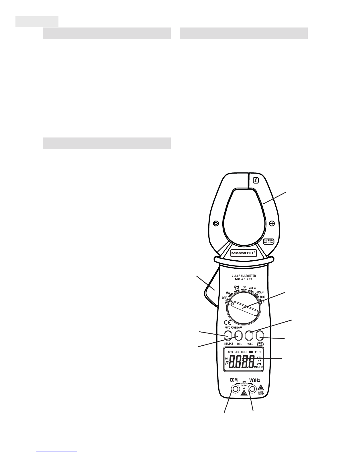
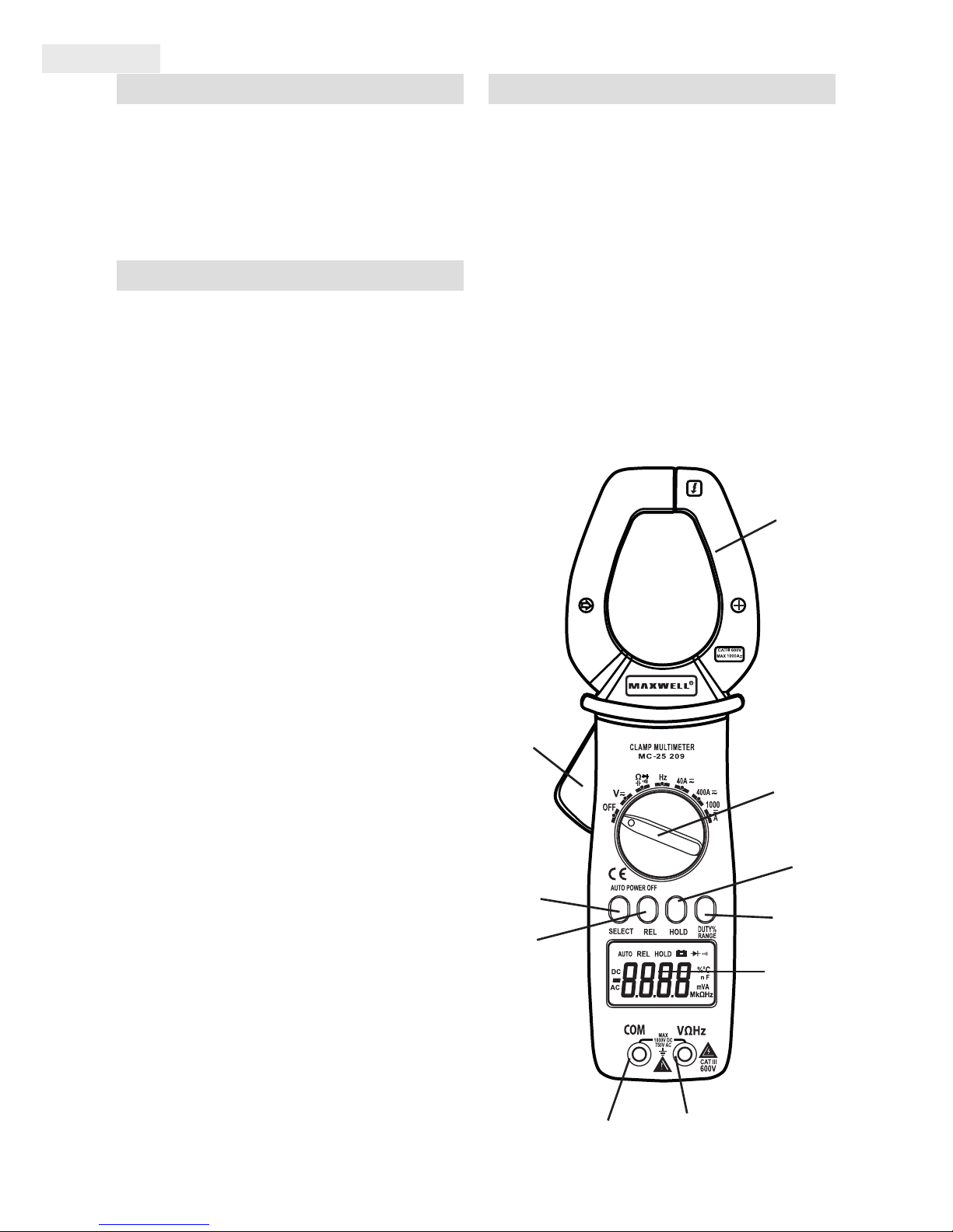
instrUMent layoUt
1. Clamp Release Button (opener)
2. Data HOLD Button
3. SELECT Button (Function Selector switch)
4. REL (relative measurement) Switch
5. RANGE/DUTY switch (selection function
and range)
6. COM connector (for connecting the black/
negative measuring wire)
7. V, Ω, CAP, Hz connector (for connecting the
red/positive measuring wire)
8. LCD Display
9. Function/Measuring selection button
10. Measuring Clamps
8.
7.
5.
2.
9.
10.
1.
4.
3.
6.
Page 3
User Manual
EN
specifications
Measuring Ranges and Accuracy
DC Current 0.01A - 1000A
AC Current 0.01A - 1000A
DC Voltage 0.1mV - 1000V
AC Voltage 1mV - 750V
Resistance 0.1Ω - 40MΩ
Capacity 1pF – 100uF
Frequency 0,001Hz-100KHz
Conductor Size 80mm opened
Diode test Opening voltage 0.3mA, voltage 1.5V DC
Continuity Limit value <50Ω; current intensity max.<1mA
Low battery power “ ” is shown on the display
Low battery power „OL” is shown on the display
Sample Rate 2/mp
Inward impedance 10MΩ (VDC és VAC)
Display 4 digites LCD
AC Current 50-60 Hz (AAC)
AC Voltage 40-400 Hz (VAC)
Operating Temperature -10°C-50°C (14°F-122°F)
Storage temperature -30°C-60°C (-22°F-140°F)
Relative Humidity max. 85%
Standard Cat III. cat. 600V
Battery DC 9V IEC 6F22.1604.
Automatically powered down After about 20 min.
Dimensions 258 x 83 x 45 mm
Súly 425 g (with battery)
DC CURRENT
Range Resolution Accuracy (%)
40A 0.01A ± (3.0% + 8 digit)
400A 0.1A ± (2.5% + 8 digit)
1000A 1A ± (3.0% + 10 digit)
Page 4
EN
User Manual
AC CURRENT
Range Resolution Accuracy (%)
40A 0.01A ± (3.0% + 10 digit)
400A 0.1A ± (2.5% + 8 digit)
1000A 1A ± (3.0% + 10 digit)
DC VOLTAGE
Range Resolution Accuracy (%)
400mV 0.1mV
± (0.5% + 4 digit)
4V 0.001V
40V 0,01V
400V 0.1V
1000V 1V ± (1.0% + 6 digit)
Input Impedance: 10MΩ
MAX. INPUT VOLTAGE: 1000V DC OR MAX. AC VALUE
AC VOLTAGE
Range Resolution Accuracy (%)
400mV 0.1mV ± (1.6% + 8 digit)
4V 0.001V
± (0.8% + 10 digit)40V 0,01V
400V 0.1V
750V 1V ± (1.0% + 10 digit)
Input Impedance: 10MΩ
Max. Input Voltage: 1000V DC or AC maximum value
Frequency Range: below 400V: 40-400Hz, above 400V: 40-200Hz
RESISTANCE
Range Resolution Accuracy (%)
400Ω 0.1Ω ± (0.8% + 5 digit)
4kΩ 1Ω
± (0.8% + 4digit)
40kΩ 10Ω
400kΩ 100Ω
4MΩ 1kΩ
40MΩ 10kΩ ± (1.2% + 10 digit)
Overload Protection: 250V DC or AC maximum
Page 5
User Manual
EN
CAPACITANCE
Range Resolution Accuracy (%)
4nF 0.001nF ± (3.5% + 30 digit)
40nF 0.01nF
± (3.0% + 5 digit)
400nF 0.1nF
4μF 0.001μF
40μF 0.01μF
100μF 0.1μF ± (5.0% + 10 digit)
FREQUENCY
Range Resolution Accuracy (%)
9,999Hz 0.001Hz
± (1.5% + 2 digit)
99,99Hz 0,01Hz
999,9Hz 0,1Hz
9,999kHz 1Hz
99,99kHz 10Hz
Input Voltage Range: min. 2V RMS
Overload Protection: 250V DC or AC maximum
cUrrent MeasUreMent
1.: Set rotary switch to the „1000A, 400A” or
„40A” position then select the voltage type
(AC or DC) by pushing the „SELECT” button.
Press the trigger to open the transformer
jaws and clamp onto one conductor only.
NOTE: During current measurement, keep
the transformerjaws fully closed. Otherwise,
accurate measurement cannot be made.
Warning: Do not make current measurement
with the test leads connected to the instrument.
voltage MeasUreMent
Set the rotary switch to the „V” range then by
the „SELECT” button select the voltage type,
DC or AC voltage.
Connect the black and red test leads to the
„COM” and „VΩHz” terminals.
Connect the test leads to the circuit being
measured.
Read the displayed value on the instrument’s
screen.
resistance MeasUreMent
Set the rotary switch to the „Ω” range.
Connect the black and red test leads to the
„COM” and „VΩHz” terminals.
Connect the test leads to the circuit being
measured.
Read the displayed value on the instrument’s
screen.
WARNING: Always make sure that the circuit
under test is powered o.
capacitance MeasUreMent
Set the rotary switch to „- | | -” range.
Connect the black test leads to the „COM”
Page 6

EN
User Manual
and the red test leads to „VΩHz” terminals.
Connect the test leads to the capacitor being
measured and read the displayed value on
the screen
NOTE: The meter only do automatically capacitance measurement.
WARNING: To avoid electrical shock and/or
damage to the instrument, disconnect circuit
power and discharge all high-voltage capacitors before measuring capacitance.
freqUency MeasUreMent
Set the rotary switch to „Hz” range.
Press the „Hz/DUTY” key to select the measurement function (frequency or duty cycle
measurement).
Connect the black test leads to the „COM”
and the red test leads to „VΩHz” terminals.
Connect the test leads to the circuit under
test and read the displayed value on the screen.
NOTE: The meter only do automatic frequency measurement.
diode test
Set the rotary switch to “ ” range.
Press the „SELECT” key once to activate Diode
Test.
Connect the black test leads to the „COM”
and the red test leads to „VΩHz” terminals.
Connect the test leads to the diode terminals
of the circuit under test and read the displayed value on the screen.
continUity cHeck
Set the function switch to “ ” range. Push
the „SELECT” button to select the continuity
check mode.
Connect the black test leads to the „COM” and
the red test leads to „VΩHz” terminals.
Connect the test leads to the circuit under test
and read the displayed value on the screen.
If the resistance is less than approximately
50Ω, an audible signal will sound.
WARNING: Always make sure that the circuit
under test is powered o.
NOTE: To avoid electrical shock and damage
to the instrument or faulty measurement,
disconnect circuit power and discharge all
high-voltage capacitors before measuring
continuity
relative MeasUreMent Mode
The Relative mode permits the user to store a
reference reading and compare all subsequent readings to the stored reference value by
pressing the „REL” button the instrument will
store the valued measure as 0. Subsequent
readings will display a value that is the dierence between the actual reading and the
stored reference value.
1. Press the „REL” key when the desired valued is displayed on the meter. This becomes
the stored reference. The „REL” symbol will
appear on the LCD.
2. Take measurements and note that the meter displays the actual reading minus the reference reading.
3. Press the „REL” key to return to normal operation. The „REL” symbol will switch o.
data Hold
To freeze the LCD meter reading, press the
„HOLD” button once during measurement
process. While data hold is active, the „HOLD”
signal appears on the LCD, an audible sound
can be heard and the instrument will store
the measured value. Press the „HOLD” button
again to return to normal operation.
sleep fUnction
This function causes the instrument to automatically enter the sleep (powered down)
mode about 20 minutes after the last switch
Page 7

User Manual
EN
or button operation. To exit the sleep mode,
turn the function selector switch back to any
position, or press any button. Befor activating
the istrument, make sure that the test leads
are not connected to any circuit in order to
avoid any damage or electrical shock.
Battery replaceMent
Replace the battery as soon as the battery indicator appears on the screen to avoid false
readings.
To replace the 9V (IEC 6F22) battery:
Turn the Meter o and remove all the connections from the input terminals.
Set the function selector to “OFF” position.
Turn the Meter’s front case down.
Remove the screw from the battery compartment, and separate the battery compartment
from the case bottom.
Take out the old battery and replace with a
new 9V battery (IEC 6F22).
Rejoin the case bottom and the battery compartment, and reinstall the screw.
Maintenance
• Periodically wipe the case with a damp
cloth and mild detergent.
• Do not use abrasives or solvents.
• Dirt or moisture in the terminals can aect
readings.
To clean the terminals:
- Turn the meter o and remove all test
leads.
- Shake out any dirt that may be in the
terminals.
- Soak a new swab with a cleaning and oiling
agent.
- Work the swab around in each terminal.
The oiling agent insulates the terminals from
moisture-related contamination
Warnings
• The rotary switch should be placed in the
correct position to prevent the Clamp Meter
during measurement process.
• Pay attention when you apply more than
50V. If the value to be measured is unknown,
use the maximum measurement position
and reduce the range step by step until a satisfactory reading is obtained.
• Use the proper terminals, functions, and
range for your measurements.
• When servicing the Clamp Meter, use only
the same model number or identical electrical specications replacement parts.
• Do not apply more than the rated voltage,
as marked on the Meter, between the terminals or between any terminal and ground. If
the value to be measured is unknown, use
the maximum measurement position and reduce the range step by step until satisfactory
reading is obtained.
Page 8
HU
Használati utasítás
Biztonsági inforMáció
Ez a segédlet tartalmazza a műszer helyes és
biztonságos használatához szükséges tudnivalókat. Amennyiben nem követi a megfelelő
utasításokat, az a műszer meghibásodásához
vezethet.
figyelMeztetés!
Olvassa el gyelmesen a használati utasításban leírtakat, mielőtt használatba venné a
készüléket.
Kövesse a biztonsági és használati instrukciókat, hogy biztosítsa a maximális személyi
biztonságot a műszer használata alatt.
Soha ne vizsgálja a megengedett maximum
bemeneti értéket a méréseknél!
Ne kíséreljen meg mérést végezni tűzveszélyes területeken, füst, pára vagy por közelében.
Ne használja a műszert ha annak burkolata
vagy az Ön keze vizes/nedves!
Soha ne nyissa ki az elemtartót, ha mérést
végez!
Mindig ellenőrizze a műszert és a mérővezetékeket mérés előtt. Ha a műszeren vagy
annak tartozékain bármilyen szerkezeti hibát
észlel, pl. a vezetékek törése, a készülékház
megrepedése, ne használja azt.
Ne forgassa a funkciókapcsolót addig, amíg
bármilyen áramkör van csatlakoztatva a műszerhez.
Ne használjon cserealkatrészeket, és ne módosítsa a készülék áramköreit. A javítást vagy
hitelesítést végeztesse szakemberrel.
Mindig kapcsolja ki a műszert és csatlakoztassa le az ármakörről mielőtt elemet cserélne.
Soha ne cserélje ki az elemet ha a műszer
vagy az ön keze vizes/nedves.
Mérések előtt győződjön meg róla, hogy a
megfelelő pozícióba állította a funkciókapcsolót.
Ne tegye ki a műszert erős napsugárzásnak
vagy nedves, poros környezeti hatásnak.
felépítés
1. Lakatfogó fej nyitó
2. HOLD (adattartás) gomb
3. SELECT (funkcióváltó) gomb
4. REL (relative mérés) gomb
5. RANGE/DUTY (Range- és üzemmód váltó)
gomb
6. COM (közös mérőbemenet a fekete műszerzsinórnak) aljzat
7. V, Ω, CAP, Hz (mérőbemenet a piros műszerzsinórnak) aljzat
8. LCD kijelző
9. Mérés üzemmód kapcsoló
10. Lakatfogó fej
8.
7.
5.
2.
9.
10.
1.
4.
3.
6.
Page 9

Használati utasítás
HU
specifikáció
MÉRÉSHATÁR
DC Áram 0.01A - 1000A
AC Áram 0.01A - 1000A
DC Feszültség 0.1mV - 1000V
AC Feszültség 1mV - 750V
Ellenállás 0.1Ω - 40MΩ
Kapacitás 1pF – 100uF
Frekvencia 0,001Hz-100KHz
Befogó mérete 80mm nyitott állapotban
Diódateszt nyitó áram 0.3mA, feszültség 1.5V DC
Folytonosság határérték <50Ω; áramerősség max.<1mA
Alacsony elem feszültség “ ” kijelzése
Túl magas érték „OL” kijelzés
Mérési mintavétel 2/mp
Bemeneti impedancia 10MΩ (VDC és VAC)
Kijelző 4 digites LCD
AC áram 50-60 Hz (AAC)
AC feszültség 40-400 Hz (VAC)
Működési hőmérséklet -10°C-50°C (14°F-122°F)
Tárolási hőmérséklet -30°C-60°C (-22°F-140°F)
Relatív páratartalom max. 85%
Érintésvédelmi osztály III. kategória 600V
Elem DC 9V IEC 6F22.1604.
Automata kikapcsolás kb. 20 min.
Méretek 258 x 83 x 45mm
Súly 425 g (elemmel)
DC ÁRAM
Méréshatár Felbontás
Pontosság
(% olvasott érték)
40A 0.01A ± (3.0% + 8 digit)
400A 0.1A ± (2.5% + 8 digit)
1000A 1A ± (3.0% + 10 digit)
Page 10

HU
Használati utasítás
AC ÁRAM
Méréshatár Felbontás
Pontosság
(% olvasott érték)
40A 0.01A ± (3.0% + 10 digit)
400A 0.1A ± (2.5% + 8 digit)
1000A 1A ± (3.0% + 10 digit)
DC FESZÜLTSÉG
Méréshatár Felbontás
Pontosság
(% olvasott érték)
400mV 0.1mV
± (0.5% + 4 digit)
4V 0.001V
40V 0,01V
400V 0.1V
1000V 1V ± (1.0% + 6 digit)
Bemeneti impedancia: 10MΩ
Túlterhelés védelem: 1000V DC vagy AC csúcsérték
AC FESZÜLTSÉG
Méréshatár Felbontás
Pontosság
(% olvasott érték)
400mV 0.1mV ± (1.6% + 8 digit)
4V 0.001V
± (0.8% + 10 digit)40V 0,01V
400V 0.1V
750V 1V ± (1.0% + 10 digit)
Bemeneti impedancia: 10MΩ
Túlterhelés védelem: 1000V DC vagy AC csúcsérték
Frekvencia függőség: 400V alatt: 40-400Hz; 400V felett:40-200Hz
ELLENÁLLÁS
Méréshatár Felbontás
Pontosság
(% olvasott érték)
400Ω 0.1Ω ± (0.8% + 5 digit)
4kΩ 1Ω
± (0.8% + 4digit)
40kΩ 10Ω
400kΩ 100Ω
4MΩ 1kΩ
40MΩ 10kΩ ± (1.2% + 10 digit)
Túlterhelés védelem: 250V DC vagy AC csúcsérték
Page 11

Használati utasítás
HU
KAPACITÁS
Méréshatár Felbontás
Pontosság
(% olvasott érték)
4nF 0.001nF ± (3.5% + 30 digit)
40nF 0.01nF
± (3.0% + 5 digit)
400nF 0.1nF
4μF 0.001μF
40μF 0.01μF
100μF 0.1μF ± (5.0% + 10 digit)
FREKVENCIA
Méréshatár Felbontás
Pontosság
(% olvasott érték)
9,999Hz 0.001Hz
± (1.5% + 2 digit)
99,99Hz 0,01Hz
999,9Hz 0,1Hz
9,999kHz 1Hz
99,99kHz 10Hz
Érzékenység: min. 2V RMS
Túlfeszültség védelem: 250V DC vagy AC csúcsérték
áraMMérés
Állítsa a funkciókapcsolót az „1000A, 400A”
vagy a „40A” pozícióba, majd a „SELECT”
gomb megnyomásával válassza ki az currenttípust, „DC” – egyenáram, „AC” – váltóáram.
Nyomja meg a lakatfogó nyitó gombot, hogy
kinyíljon a befogópofa és fogja körbe a vezetéket. Olvassa le a mért értéket.
Megjegyzés: Currentméréskor legyen a lakatfogó fej szorosan zárva, különben befolyásolhatja a mérés pontosságát.
VIGYÁZAT: Ügyeljen rá, hogy a műszerzsinórok ne legyenek csatlakoztatva a műszerhez amikor a lakatfogó mérést végez.
feszültség Mérés
Állítsa a funkciókapcsolót a „V” állásba majd
a „SELECT” gomb megnyomásával válassza
ki a feszültség típust, „DC” – egyenfeszültség,
„AC” – váltófeszültség. Csatlakoztassa a piros
mérőzsinórt a „V•Ω•HZ” aljzatba és a fekete
mérőzsinórt a „COM” aljzatba. Csatlakoztassa
a műszerzsinórok végeit a mérendő áramkörbe. Olvassa le a mért értéket.
ellenállás Mérés
Állítsa a funkciókapcsolót „Ω” állásba.
Csatlakoztassa a piros mérőzsinórt a „V•Ω•-
HZ” aljzatba, és a fekete mérőzsinórt a „COM”
aljzatba. Csatlakoztassa a műszerzsinórok végeit a mérendő áramkör ellenállás kivezetéseibe. Olvassa le a mért értéket.
Figyelmeztetés! Mielőtt belekezdene az ellenállás mérésbe, győződjön meg róla, hogy
nincs-e feszültségre kötve az áramkör.
kapacitás Mérés
Page 12

HU
Használati utasítás
Állítsa a funkciókapcsolót a „- | | -” tarto-
mányba. Csatlakoztassa a piros mérőzsinórt
a „V•Ω•HZ” aljzatba, és a fekete mérőzsinórt
a „CO M” aljzatba. Érintse a vezetékek végét a
mérendő áramkör kondenzátor kivezetéseibe. Olvassa le a mért értéket.
Megjegyzés: A műszer csak automata kapacitás mérést végez.
Figyelmeztetés! A műszer károsodásának
elkerülésére győzödjön meg róla, hogy a mérendő áramkör nincsen feszültség alatt, ill. a
mérendő kondenzátor ki van sütve. Nagyértékű kondenzátorokat mindig megfelelő
ellenállás segítségével süsse ki, majd DC feszültségméréssel győződjön meg róla, hogy
a kondenzátor nincs feszültség alatt.
frekvencia Mérés
Állítsa a funkciókapcsolót a „Hz” tartományba. Nyomja a „RANGE/DUTY” gombot, hogy
kiválassza a mérési funkciót (frekvencia vagy
kitöltési tényező). Csatlakoztassa a piros mérőzsinórt a „V•Ω•HZ” aljzatba, és a fekete mérőzsinórt a „COM” aljzatba. Érintse a vezetékek végét a mérendő áramkör kivezetéseibe.
Olvassa le a mért értéket.
Megjegyzés: A műszer csak automata frekvencia mérést végez.
dióda teszt
Állítsa a funkciókapcsolót “ ” pozícióba.
Nyomja meg a „SELECT” gombot, hogy a diódamérést kiválassza. Csatlakoztassa a piros
mérőzsinórt a „V•Ω•HZ” aljzatba, és a fekete
mérőzsinórt a „COM” aljzatba. Érintse a műszerzsinórok végeit a mérendő áramkör dióda kivezetéseibe.
Olvassa le a mért értéket.
folytonossági teszt
Állítsa a funkciókapcsolót “ ” pozicióba.
Nyomja meg a „SELECT” gombot a folytonosság teszt kiválasztásához. Csatlakoztassa
a piros mérőzsinórt a „V•Ω•HZ” aljzatba, és a
fekete mérőzsinórt a „COM” aljzatba. Érintse
a műszerzsinórok végeit a mérendő áramkör kivezetéseibe. Olvassa le az eredményt
a kijelzőről. A kijelző mutatni fogja az eredményt, a műszer pedig sípoló hanggal jelzi,
ha az olvasott érték kevesebb, mint 50Ω.
Figyelmeztetés: Mérés előtt győződjön meg
róla, hogy a mért áramkör nincs feszültség
alatt!
Megjegyzés: Feszültség alatti áramkör mérése hamis eredményt produkál, illetve kárt
okozhat a készülékben!
relatív Mérési Mód
A relatív mérési mód, a mérés folyamán először egy referencia jelet mérve majd a „REL”
gombot megnyomva az éppen mért értéket
tekinti műszer 0 szintnek. A kijelzőn ekkor a
REL felirat jelenik meg és ezentúl ehhez viszonyítja a mérendő értéket. A „REL” gomb újbóli
megnyomásával a funkció kikapcsolható.
adattartás fUnkció
Mérés közben nyomja meg a „HOLD” gombot egyszer. Ha a „HOLD” funkció aktiválódott, a műszer sípol, megtartja a mért értéket és megjelenik a HOLD felirat a kijelzőn.
A „HOLD” funkció kikapcsolásához nyomja
meg újra a „HOLD” gombot, a műszer sípolni
fog és újabb mérést végezhet.
aUtoMatikUs kikapcsolás
Ez a funkció az utolsó mérés után kb. 20 perccel automatikusan kikapcsolja a műszert. A
műszer bekapcsolásához nyomja meg valamelyik gombot vagy fordítsa el a funkciókapcsolót valamelyik pozícióba. A műszer
automatikusan kikapcsolt állapotból történő
bekapcsolása előtt ellenőrizze, hogy a vezetékek nincsenek csatlakoztatva semmilyen
áramkörhöz, hogy elkerülje a személyi sérüléseket, illetve a műszer károsodását!
Page 13

Használati utasítás
HU
eleMcsere
Amikor az akkumulátor ikon megjelenik a
kijelzőn, akkor az elem feszültsége már alacsony, ilyenkor ki kell cserélni az elemet. Kövesse az alábbi utasításokat a 9V-os (IEC 6F22)
elemcseréhez: Csatlakoztassa le a műszerzsinórokat minden áramkörről és távolítsa el a
műszerzsinórokat a bemeneti csatlakozókról.
Állítsa a funkciókapcsolót az „OFF” pozícióba.
Az elemtartó fedél kinyitásához használjon
csavarhúzót. Távolítsa el az elhasznált elemet
és cserélje ki az új IEC 6F22 9V-os elemre. Csavarozza vissza az elemtartó fedelét.
kezelés
• Tartsa a multimétert szárazon. Ha nedvesség éri, törölje le azonnal. A folyadékok korrodálják az áramköröket.
• A multimétert tárolni és használni csak
normál hőmérsékleten szabad. A magas hőmérséklet rövidíti az elektronikus eszközök
élettartamát, megrongálja az elemeket, és
eltorzítja, megolvasztja a műanyag alkatrészeket.
• Bánjon óvatosan és gondosan a multiméterrel, az elejtés kárt tesz az áramkörökben és a
tokban, ami a multiméter helytelen működését okozhatja.
• Óvja a multimétert a portól és egyéb szenynyeződésektől, amik az alkatrészek idő előtti
kopását eredményezik.
• A multimétert nedves ruhával tisztíthatja.
Ne alkalmazzon vegyszereket, oldószereket
vagy erős tisztítószereket a tisztításhoz.
figyelMeztetés
• Feszültség mérésénél ügyeljen rá, hogy a
funkciókapcsoló a megfelelő állásban legyen
• Legyen körültekintő 50 V-nál nagyobb feszültség mérésekor, különösen erősáramú berendezéseknél.
• Ellenállásmérés és dióda tesztelés előtt gondoskodjon az áramkör feszültségmentesítéséről a mérés idejére.
• Mindig a mérésnek megfelelő funkciót és
Ranget válassza. Ha kétséges a mérendő
mennyiség nagyságrendje, válassza a legmagasabb Ranget és onnan haladjon visszafelé.
Page 14

RO
Manual de utilizare
inforMaţii de sigUranţă
Vă rugăm să urmaţi instrucţiunile din acest
document, altfel riscând buna funcţionare a
aparatului.
atenţiUne!
Nu măsuraţi valorile maxime admise de
aparat.
Nu executaţi măsurări în spaţii cu pericol de
incendiu sau explozie, sau în mediu cu vapori, fum, sau praf abundent.
Nu folosiţi aparatul dacă carcasa acestuia sau
mâinile Dvs. sunt ude.
Nu rotiţi selectorul de funcţii cu cablurile
conectate la vreun circuit electric.
Nu încercaţi repararea domestică a aparatului. În cazul unor malfuncţionări, apelaţi la un
specialist autorizat.
constrUcţie
1. Cap cleşte
3. HOLD (stocare valori)
3. SELECT (selectare funcţii)
4. REL (valoare relativă)
5. RANGE/DUTY (domeniu şi mod de măsurare)
6. COM (mufă intrare comună, cablu negru
7. V, Ω, CAP, Hz (mufă intrare măsurare – cablu
roşu)
8. LCD
9. Comutator mod măsurare
10. Cap cleşte
8.
7.
5.
2.
9.
10.
1.
4.
3.
6.
Page 15

Manual de utilizare
RO
specificaţii
Domeniu de măsurare
Curent CC 0.01A - 1000A
Curent CA 0.01A - 1000A
Tensiune CC 0.1mV - 1000V
Tensiune CA 1mV - 750V
Rezistenţă 0.1Ω - 40MΩ
Capacitate 1pF – 100uF
Frecvenţă 0,001Hz-100KHz
Dimensiune utilă cleşte 80mm în stare deschisă
Test diodă I desch. 0.3mA, Tens. 1.5V CC
Continuitate limită <50Ω; I max.<1mA
Semn. baterie epuizată aşare “ ”
Depăşire val. max. simbol „OL”
Frecv. de eşantionare 2/sec.
Impedanţa de intrare 10MΩ (VCC şi V CA)
Aşaj 4 digit LCD
Curent CA 50-60 Hz (AAC)
Tens. CA 40-400 Hz (VAC)
Temp. de lucru -10°C-50°C (14°F-122°F)
Temp. de depozitare -30°C-60°C (-22°F-140°F)
Umiditate rel. max. 85%
Clasa de protecţie Cat. III. 600V
Baterie DC 9V IEC 6F22.1604.
Decuplare automată cca. 20 min.
Dimensiuni 258 x 83 x 45mm
Masa 425 g
CURENT CC
Domeniu de
măsurare
Rezoluţie Precizie (% Val. aşată)
40A 0.01A ± (3.0% + 8 digit)
400A 0.1A ± (2.5% + 8 digit)
1000A 1A ± (3.0% + 10 digit)
Page 16

RO
Manual de utilizare
CURENT CA
Domeniu de
măsurare
Rezoluţie
Precizie
(% Val. aşată)
40A 0.01A ± (3.0% + 10 digit)
400A 0.1A ± (2.5% + 8 digit)
1000A 1A ± (3.0% + 10 digit)
TENSIUNE CC
Domeniu de
măsurare
Rezoluţie
Precizie (% Val.
aşată)
400mV 0.1mV
± (0.5% + 4 digit)
4V 0.001V
40V 0,01V
400V 0.1V
1000V 1V ± (1.0% + 6 digit)
Impedanţa de intrare: 10MΩ
Protecţia la suprasarcină: 1000V CC sau CA val. de vârf
TENSIUNE CA
Domeniu de
măsurare
Rezoluţie
Precizie (% Val.
aşată)
400mV 0.1mV ± (1.6% + 8 digit)
4V 0.001V
± (0.8% + 10 digit)40V 0,01V
400V 0.1V
750V 1V ± (1.0% + 10 digit)
Impedanţa de intrare: 10MΩ
Protecţia la suprasarcină: 1000V CC sau CA val. de vârf
Răspuns la frecvenţă: sub 400V: 40-400Hz; peste 400V: 40-200Hz
REZISTENŢĂ
Domeniu de
măsurare
Rezoluţie
Precizie
(% Val. aşată)
400Ω 0.1Ω ± (0.8% + 5 digit)
4kΩ 1Ω
± (0.8% + 4digit)
40kΩ 10Ω
400kΩ 100Ω
4MΩ 1kΩ
40MΩ 10kΩ ± (1.2% + 10 digit)
Protecţie la suprasarcină: 250V CC sau CA v-v
Page 17

Manual de utilizare
RO
CAPACITATE
Domeniu de
măsurare
Rezoluţie
Precizie
(% Val. aşată)
4nF 0.001nF ± (3.5% + 30 digit)
40nF 0.01nF
± (3.0% + 5 digit)
400nF 0.1nF
4μF 0.001μF
40μF 0.01μF
100μF 0.1μF ± (5.0% + 10 digit)
FRECVENŢĂ
Domeniu de
măsurare
Rezoluţie
Precizie
(% Val. aşată)
9,999Hz 0.001Hz
± (1.5% + 2 digit)
99,99Hz 0,01Hz
999,9Hz 0,1Hz
9,999kHz 1Hz
99,99kHz 10Hz
Sensibilitate: min. 2V RMS
Protecţie la supratensiune: 250V CC sau CA p-p
MăsUrarea cUrentUlUi
Comutaţi comutatorul de funcţii în poz.
„1.000A, 400A” sau „40A”. Cu butonul SELECT selectaţi tip curent CC sau CA.
Prin apăsarea butonului de deschidere,
deschideţi fălcile cleştelui şi cuprindeţi cablul
de măsurat. Citiţi valoarea aşată.
Notă: În timpul măsurării fălcile cleştelui
trebuie să e închise perfect, orice rost inuenţând precizia de măsurare.
Atenţie: Cablurile de măsurare nu trebuie
să e conectate în timpul măsurării în mod
clampmetru.
MăsUrarea tensiUnii
Comutaţi comutatorul de funcţii în poz. „V”.
Cu butonul „SELECT” selectaţi tip curent CC
sau CA.
Conectaţi cablul de măsurare roşu în mufa
„V•Ω•HZ” şi cel negru în mufa „COM”. Conec-
taţi cablurile la circuitul de măsurat
şi citiţi valoarea măsurată.
MăsUrarea rezistenţei
Comutaţi comutatorul de funcţii în poz. „Ω”
. Conectaţi cablul de măsurare roşu în mufa
„V•Ω•HZ” şi cel negru în mufa „COM”.
Conectaţi cablurile la circuitul de măsurat şi
citiţi valoarea măsurată.
Atenţie: Înainte de măsurarea rezistenţei,
convingeţi-vă ca circuitul să nu e sub tensiune.
MăsUrarea capacităţii
Comutaţi comutatorul de funcţii în poz. „- | |
-”. Conectaţi cablul de măsurare roşu în mufa
„V•Ω•HZ” şi cel negru în mufa „COM”.
Conectaţi cablurile la circuitul de măsurat şi
citiţi valoarea măsurată.
Atenţie: Înainte de măsurarea rezistenţei,
Page 18

RO
Manual de utilizare
convingeţi-vă ca circuitul să nu e sub tensiune şi condensatorul să nu e
încărcat.
MăsUrarea frecvenţei
Comutaţi comutatorul de funcţii în poz.
„Hz”. Prin butonul „RANGE/DUTY” selectaţi
modul „Frecvenţă” sau „Factor de umplere”.
Conectaţi cablul de măsurare roşu în mufa
„V•Ω•HZ” şi cel negru în mufa „C O M ”. Conectaţi cablurile la circuitul de măsurat şi citiţi
valoarea măsurată.
Atenţie: Înainte de măsurarea rezistenţei,
convingeţi-vă ca circuitul să nu e sub tensiune şi condensatorul să nu e încărcat.
testare diodă
Comutaţi comutatorul de funcţii în poz. “
”. Prin butonul „SELECT” selectaţi modul de
măsurare diodă. Conectaţi cablul de măsurare roşu în mufa „V•Ω•HZ” şi cel negru în mufa
„COM” Conectaţi cablurile la circuitul de măsurat şi citiţi valoarea măsurată.
test continUitate
Comutaţi comutatorul de funcţii în poz. “
”. Prin butonul „SELECT” selectaţi modul de
testare continuitate.
Conectaţi cablul de măsurare roşu în mufa
„V•Ω•HZ” şi cel negru în mufa „C O M ”. Conectaţi cablurile la circuitul de măsurat şi citiţi
valoarea măsurată. Aparatul va emite semnal
sonor în cazul în care rezistenţa circuitului
este sub 50Ω.
Atenţie: Înainte de măsurarea rezistenţei,
convingeţi-vă ca circuitul să nu e sub tensiune deoarece acesta poate deteriora aparatul.
ModUl de MăsUrare relativ
După măsurarea unei valori de referinţă se
apasă butonul „REL” Pe aşaj va apare simbo-
lul „REL” şi valoarea măsurată va reprezenta
diferenţa faţă de valoare de referinţă xată
anterior. Prin apăsarea repetată a butonului
„REL”, funcţia se dezactivează.
fUncţia de stocare a valorii MăsUrate
În timpul măsurării apăsaţi butonul „HOLD”
aparatul va emite un semnal sonor şi pe aşaj
va apare simbolul „HOLD” . Prin apăsarea repetată a butonului „HOLD”, aparatul va emite
din nou un semnal sonor şi funcţia se dezactivează.
decUplare aUtoMată
Această funcţie decuplează automat aparatul după cca. 20 de minute de inactivitate.
Pt. recuplare apăsaţi oricare buton, sau rotiţi
butonul de selectare a funcţiilor. Înainte de
recuplare, convingeţi-vă ca aparatul să nu e
conectat la nici un circuit.
scHiMBarea Bateriei
Apariţia simbolului de baterie pe aşaj, reprezintă epuizare bateriei din aparat. Schimbarea bateriei 9V (IEC 6F22) se face după cum
urmează:
Deconectaţi cablurile de măsurare de la orice circuit electric. Comutaţi comutatorul de
funcţii în. poz. OFF. Îndepărtaţi capacul bateriei şi înlocuiţi bateria cu una de tip identic cu
originalul. Reaşezaţi capacul bateriei.
Întreţinere
· Păstraţi aparatul în mediu uscat. În caz de
umezire ştergeţi de urgenţă aparatul.
· Aparatul va păstrat şi folosit numai la temperaturi normale.
· Feriţi aparatul de şocuri şi lovituri
· Feriţi aparatul de praf şi alte impurităţi
· Aparatul va curăţat cu o cârpă moale, us-
cată fără folosirea de detergenţi sau solvenţi.
Page 19

Manual de utilizare
RO
atenţie
· La măsurarea tensiunii vericaţi poziţia selectorului de funcţii.
· Atenţie la normele de electrosecuritate la
măsurarea tensiunilor de peste 50V.
· La măsurarea rezistenţei şi test diodă, circuitul de măsurat va scos de sub tensiune.
· Folosiţi funcţiile şi modurile de măsurare
adecvate valorilor electrice de măsurat, pornind mereu de la un domeniu mai mare spre
cel mai mic.
Page 20

SK
Uživateľská príručka
Bezpečnostné inforMácie
Tento návod obsahuje informácie potrebné
pre správne a bezpečné použitie meracieho
prístroja. V prípade nedodržania dole popísaných pokynov môže dôjsť k poškodeniu meracieho prístroja.
Upozornenie!
Prečítajte si pozorne tento návod na použitie
ešte pred prvým použitím meracieho prístroja.
Dbajte na pokyny týkajúce sa bezpečnosti a
použitia meracieho prístroja preto, aby bola
zabezpečená maximálna osobná bezpečnosť.
Pri meraní nikdy neprekračujte maximálne
vstupné meracie hodnoty!
Nepokúšajte sa prevádzať meranie v priestoroch, kde hrozí nebezpečenstvo požiaru alebo v parnom, prašnom alebo zadymenom
prostredí.
Nedotýkajte sa meracieho prístroja ak máte
vlhké / mokré ruky!
Nikdy neotvárajte kryt baterky počas merania!
Pred každým meraním skontrolujte stav meracích šnúr a prístroja. Ak nájdete na prístroji
alebo príslušenstve akúkoľvek chybu, napr.
poškodená izolácia, prasknutý kryt a pod.,
nepoužívajte ho.
Neotáčajte prepínačom funkcií dovtedy ak je
merací prístroj pripojený na meraný obvod.
Merací prístroj neopravujte, neupravujte a
nezasahujte do jeho konštrukcie. Akékoľvek
opravy a kalibráciu zverte do rúk odborníkom.
Pred výmenou batérie odpojte všetky merané obvody a vypnite merací prístroj.
Baterku meracieho prístroja nevymieňajte ak
máte vlhké / mokré ruky.
Pred každým meraním sa ubezpečte o tom,
že je správne nastavená meracia funkcia.
Merací prístroj nevystavujte priamemu slnečnému žiareniu, parnému alebo prašnému
prostrediu.
popis
1. Otváranie klieští
2. HOLD (uloženie hodnoty) tlačidlo
3. SELECT (zmena funkcií) tlačidlo
4. REL (relatívne meranie) tlačidlo
5. RANGE/DUTY (zmena meracieho rozsahu,
režimu) tlačidlo
6. COM (spoločný vstup pre čierny meraciu
šnúru) konektor
7. V, Ω, CAP, Hz (merací vstup pre červenú meraciu šnúru) konektor
8. LCD displej
9. Otočný prepínač meracích funkcií
10. Kliešte meracieho prístroja
8.
7.
5.
2.
9.
10.
1.
4.
3.
6.
Page 21

Uživateľská príručka
SK
tecHnické údaje
MERACÍ ROZSAH
Jednosmerný prúd 0.01A - 1000A
Striedavý prúd 0.01A - 1000A
Jednosmerné napätie 0.1mV - 1000V
Striedavé napätie 1mV - 750V
Odpor 0.1Ω - 40MΩ
Kapacita 1pF – 100uF
Frekvencia 0,001Hz-100KHz
Rozmery klieští 80mm otvorenom stave
Test diód otvárací prúd 0.3mA, napätie 1.5V DC
Test kontinuity Hraničná hodnota <50Ω; veľkosť prúdu max.<1mA
Vybitá baterka “ ” na displeji
Prekročenie meracieho rozsahu „OL” na displeji
Odber vzoriek 2/mp
Vstupná impedancia 10MΩ (VDC és VAC)
Displej 4 číslicový LCD
Striedavý prúd 50-60 Hz (AAC)
Striedavé napätie 40-400 Hz (VAC)
Prevádzková teplota -10°C-50°C (14°F-122°F)
Skladovacia teplota -30°C-60°C (-22°F-140°F)
Relatívny obsah pary max. 85%
Kategória merania III. kategória 600V
Batéria DC 9V IEC 6F22.1604.
Automické vypnutie asi . 20 min.
Rozmery 258 x 83 x 45mm
Hmotnosť 425 g
DC PRÚD
Merací rozsah Rozlíšenie
Presnosť (% nameranej
hodnoty)
40A 0.01A ± (3.0% + 8 digit)
400A 0.1A ± (2.5% + 8 digit)
1000A 1A ± (3.0% + 10 digit)
Page 22

SK
Uživateľská príručka
AC PRÚD
Merací rozsah Rozlíšenie
Presnosť (% nameranej
hodnoty)
40A 0.01A ± (3.0% + 10 digit)
400A 0.1A ± (2.5% + 8 digit)
1000A 1A ± (3.0% + 10 digit)
DC NAPÄTIE
Merací rozsah Rozlíšenie
Presnosť (% nameranej
hodnoty)
400mV 0.1mV
± (0.5% + 4 digit)
4V 0.001V
40V 0,01V
400V 0.1V
1000V 1V ± (1.0% + 6 digit)
Vstupná impedancia: 10MΩ
Ochrana proti preťaženiu: 1000V DC alebo AC špičková hodnota
AC NAPÄTIE
Merací rozsah Rozlíšenie
Presnosť (% nameranej
hodnoty)
400mV 0.1mV ± (1.6% + 8 digit)
4V 0.001V
± (0.8% + 10 digit)40V 0,01V
400V 0.1V
750V 1V ± (1.0% + 10 digit)
Vstupná impedancia: 10MΩ
Ochrana proti preťaženiu: 1000V DC alebo AC špičková hodnota
V závislosti od frekvencie: pod 400V: 40-400Hz, nad 400V: 40-200Hz
ODPOR
Merací rozsah Rozlíšenie
Presnosť (% nameranej
hodnoty)
400Ω 0.1Ω ± (0.8% + 5 digit)
4kΩ 1Ω
± (0.8% + 4digit)
40kΩ 10Ω
400kΩ 100Ω
4MΩ 1kΩ
40MΩ 10kΩ ± (1.2% + 10 digit)
Ochrana proti preťaženiu: 250V DC alebo AC špičková hodnota
Page 23

Uživateľská príručka
SK
KAPACITA
Merací rozsah Rozlíšenie
Presnosť (% nameranej
hodnoty)
4nF 0.001nF ± (3.5% + 30 digit)
40nF 0.01nF
± (3.0% + 5 digit)
400nF 0.1nF
4μF 0.001μF
40μF 0.01μF
100μF 0.1μF ± (5.0% + 10 digit)
FREKVENCIA
Merací rozsah Rozlíšenie
Presnosť (% nameranej
hodnoty)
9,999Hz 0.001Hz
± (1.5% + 2 digit)
99,99Hz 0,01Hz
999,9Hz 0,1Hz
9,999kHz 1Hz
99,99kHz 10Hz
Citlivosť: min. 2V RMS
Ochrana proti preťaženiu: 250V DC alebo AC špičková hodnota
Meranie prúdU
Otočte prepínačom funkcíí do polohy merania prúdu, poloha „1000A, 400A“ alebo
„40A“, potom pomocou „SELECT“ tlačítka
vyberte, o ktorý druh prúdu sa jedná, „DC“ –
jednosmerný, „AC“ – striedavý.
Stlačte tlačítko pre otvorenie klieští meracieho prístroja tak, aby sa otvorili a úplne uzavreli okolo meraného vodiča.
Na displeji prečítate nameranú hodnotu.
Poznámka: Pri meraní prúdu musia byť
kliešte meracieho prístroja úplne uzavreté,
v opačnom prípade to má výrazný vplyv na
presnosť merania.
POZOR: Počas merania prúdu dbajte na to,
aby v konektoroch neboli pripojené meracie
šnúry.
Meranie napätia
Otočte prepínačom funkcíí do polohy „V“ a
potom pomocou „SELECT“ tlačítka vyberte, o
ktorý druh prúdu sa jedná, „DC“ – jednosmerný, „AC“ – striedavý. Pripojte meracie šnúry
do konektorov, červenú meraciu šnúru do
konektoru „V•Ω•HZ“ a čiernu do konektoru
„COM“. Nakoniec pripojte meracie šnúry k
meranému obvodu. Na displeji prečítate nameranú hodnotu.
Meranie odporU
Otočte prepínačom funkcíí do polohy merania odporu so znakom „Ω“. Pripojte meracie
šnúry do konektorov, červenú meraciu šnúru
do konektoru „V•Ω•HZ“ a čiernu do konektoru
„COM“. Nakoniec pripojte meracie šnúry k meranému obvodu. Na displeji prečítate nameranú hodnotu.
Upozornenie! Pred začatím merania odporu
sa ubezpečte o tom, že meraný obvod nie je
pod napätím.
Page 24

SK
Uživateľská príručka
Meranie kapacity
Otočte prepínačom funkcíí do polohy merania kapacity „- | | -“. Pripojte meracie šnúry
do konektorov, červenú meraciu šnúru do
konektoru „V•Ω•HZ“ a čiernu do konektoru
„COM“. Dotknite sa vodičov na výstupe kondenzátora v meranom obvodu. Na displeji
prečítate nameranú hodnotu.
Poznámka: Merací prístroj vykonáva iba automatickú zmenu rozsahu pri meraní kapacity.
Upozornenie! Pred začatím merania kapacity sa ubezpečte o tom, že meraný obvod
nie je pod napätím a meraný kondenzátor je
vybitý. Pri veľkých kondenzátoroch vybíjanie
prevádzajte pomocou zodpovedajúceho odporu a potom zmerajte, či kondenzátor nie je
pod napätím (DC) a je skutočne úplne vybitý
Meranie frekvencie
Otočte prepínačom funkcíí do polohy merania kapacity označenú „Hz“. Stlačte tlačítko
„RANGE/DUTY“ pre výber meracej funkcie
(frekvencia alebo vybíjací faktor - duty cycle).
Pripojte meracie šnúry do konektorov, červenú meraciu šnúru do konektoru „V•Ω•HZ“
a čiernu do konektoru „COM“. Dotknite sa
vodičov na výstupe meraného obvodu. Na
displeji prečítate nameranú hodnotu.
Poznámka: Merací prístroj vykonáva iba automatickú zmenu rozsahu pri meraní frekvencie.
test diód
Otočte prepínačom funkcíí do polohy testu
diód označenú symbolom “ ”. Stlačte tlačítko „SELECT“, pre výber testu diód. Pripojte
meracie šnúry do konektorov, červenú meraciu šnúru do konektoru „V•Ω•HZ“ a čiernu do
konektoru „COM“. Dotknite sa vodičov na výstupe diódy v meranom obvodu. Na displeji
prečítate nameranú hodnotu.
test kontinUity (skratU)
Otočte prepínačom funkcíí do polohy testu
kontinuity označenú symbolom “ ”. Stlačte
tlačítko „SELECT“, pre výber testu kontinuity.
Pripojte meracie šnúry do konektorov, červenú meraciu šnúru do konektoru „V•Ω•HZ“ a
čiernu do konektoru „COM“. Dotknite sa vodičov na výstupe diódy v meranom obvodu.
Na displeji prečítate nameranú hodnotu. Na
displeji sa zobrazí výsledná hodnota, v prípade, že je menšia ako 50Ω potom bude merací prístroj pípať a tak upozorní na jeho nízku
hodnotu.
Upozornenie: Pred začatím merania odporu
sa ubezpečte o tom, že meraný obvod nie je
pod napätím!
Popis: Ak je meraný obvod pod prúdom výrazne to zkreslí výsledok merania a naviac napätie môže spôsosbiť poškodenie meracieho
prístroja!
relatívny Merací režiM
Relatívny merací režim je taký režim, kde pri
meraní najprv zmeriate jednu porovnávaciu
hodnotu a stlačením tlačítka „REL“ potom
merací prístroj meria tak, že túto uloženú
hodnotu pokladá za 0 a všetky ďaľšie namerané hodnoty sú rozdielom oproti tejto hodnote. Na displeji meracieho prístroja bude pri
tomto meraní svietiť „REL“ nápis. Po opätov-
nom stlačení tlačítka „REL“ sa funkcia vypne
a prístroj pracuje v normálnem meracom režime.
fUnkcia Hold
Funkcia sa aktivuje krátkym stlačením tlačítka „HOLD“. Pri aktivácii funkcie „HOLD“ merací prístroj pípne, na displeji zostane svietiť
práve nameraná hodnota a zobrazí sa nápis
„HOLD“.
Pre vypnutie funkcie „HOLD“ je potrebné
znova stlačiť tlačítko „HOLD“ a prístroj pracuje v normálnem meracom režime.
Page 25

Uživateľská príručka
SK
aUtoMatické vypnUtie
Táto funkcia vypne merací prístroj po poslednom meraní asi po 20 minútach. Pre opätovné zapnutie meracieho prístroja je potrebné
stlačiť niektoré tlačidlo alebo otočiť prepínačom funkcíí na niektorú z funkcií. Po automatickom vypnutí meracieho prístroja skontrolujte, či meracie káble nie sú ešte pripojené
na meraný obvod, predídete tak prípadnému
úrazu elektrickým prúdom alebo poškodeniu
meracieho prístroja!
výMena Batérie
Keď sa na displeji zobrazí symbol batérie,
vtedy je potrebné vymeniť baterku, pretože
je už natoľko vybitá, že nedokáže plne pokryť potreby meracieho prístroja. Pri výmene
9V batérie (IEC 6F22) postupujte nasledovne: Odpojte meracie šnúry od meraného
obvodu a potom vytiahnite meracie šnúry
z konektorov na meracom prístroji. Otočte
prepínačom funkcíí do polohy vypnuté označenú symbolom „OFF“. Otvorte kryt batérie
pomocou skrutkovača. Vyberte vybitú batériu a vymeňte ju za novú rovnakého typu IEC
6F22 9V. Vložte naspäť na miesto kryt batérie
a zaskrutkujte ho.
poUžitie
• Skladujte merací prístroj na suchom mieste.
V prípade kontaktu s nejakou kvapalinou ju
okamžite utrite. Akákoľvek kvapalina môže
spôsobiť poškodenie meracieho prístroja.
• Merací prístroj je možné skladovať a používať iba za bežných teplotných podmienok.
Vysoké teploty spôsobujú zníženie životnosti
elektronických súčiastok, môžu spôsobiť poškodenie batérie a deformovať, roztopiť plastové časti.
• S meracím prístrojom zaobchádzajte opatrne a starostlivo. Prípadný pád môže poškodiť
meracie obvody alebo vonkajší obal meracieho prístroja a tak znehodnotiť alebo znemožniť ďaľšie merania.
• Chráňte merací prístroj pred prachom a
akýmkoľvek znečistením, ktoré môže spôsobiť predčasné opotrebenie pohyblivých súčiastok.
• Merací prístroj pretrite vlhkou mäkkou
handričkou. Nepoužívajte žiadne čistiace
prostriedky, rozpúšťadlá alebo iné chemické
prípravky.
Upozornenie
• Pri meraní pod napätím vždy dbajte na to,
aby otočný prepínač funkcií bol vždy v zodpovedajúcej polohe.
• Pri meraní s napätím vyšším ako 50 V buďte
opatrný, zvlášť ak sa jedná o zariadenia s trojfázovým napájaním.
• Pri meraní odporu a teste diód sa vždy ubezpečte o tom, či meraný obvod nie je počas
merania pod napätím.
• Pri meraní dbajte, aby otočný prepínač
funkcií a nastavený merací rozsah zodpovedal vykonávanému meraniu. V prípade, že nie
ste si istý veľkosťou meranej veličiny zvoľte
najvyšší možný merací rozsah a ten postupne
znižujte.
 Loading...