

Page 1

User manUal
Használati Utasítás
manUal de Utilizare
Užívateľská prírUčka
DIGITAL MULTIMETER
DIGITÁLIS MULTIMÉTER
MULTIMETRU DIGITAL
DIGITÁLNY MULTIMETER
Product code / Termékkód / Cod produs / Kód produkta:
25304
HU
RO
SK
i
VC9808+
EN
Page 2
EN
User Manual
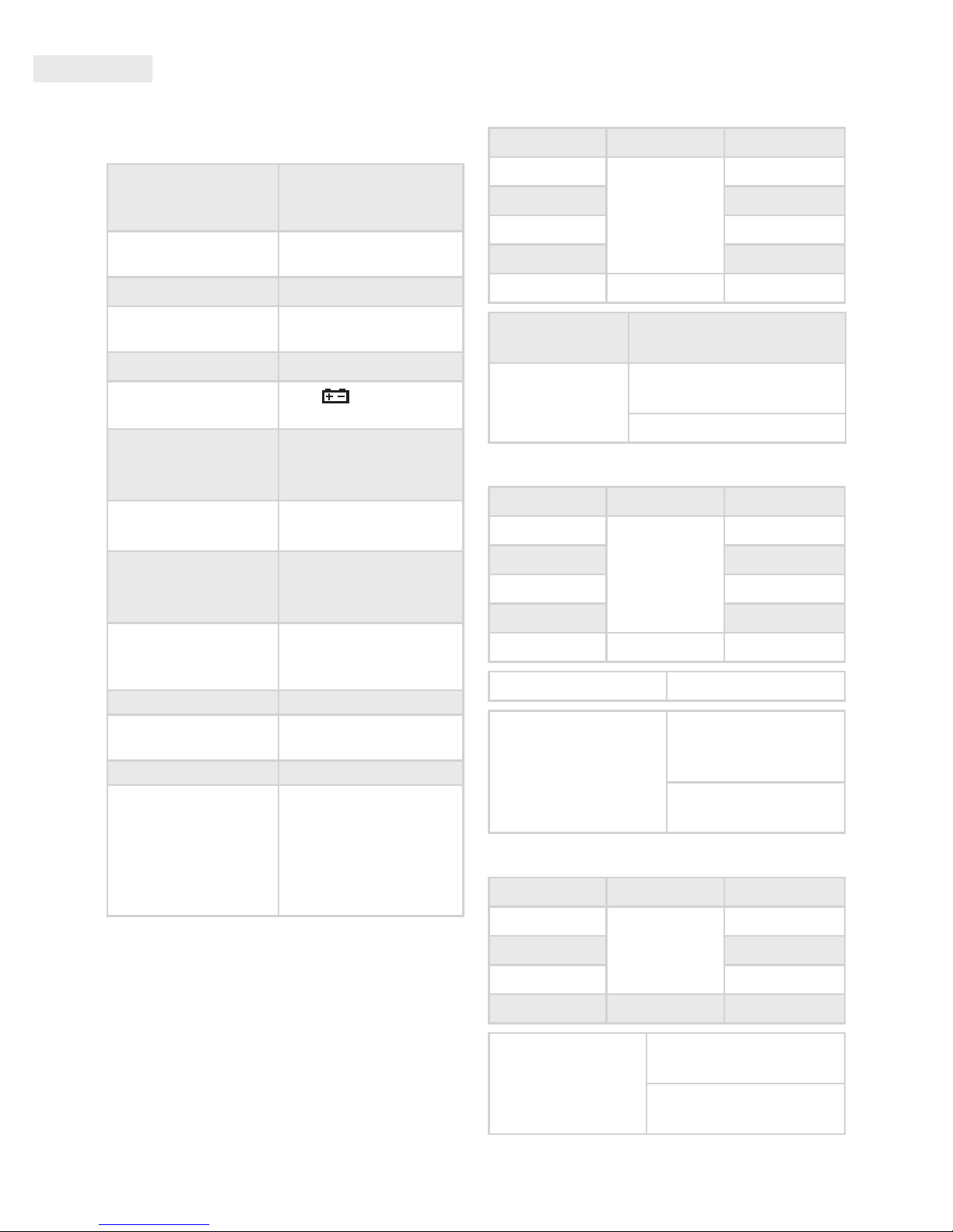
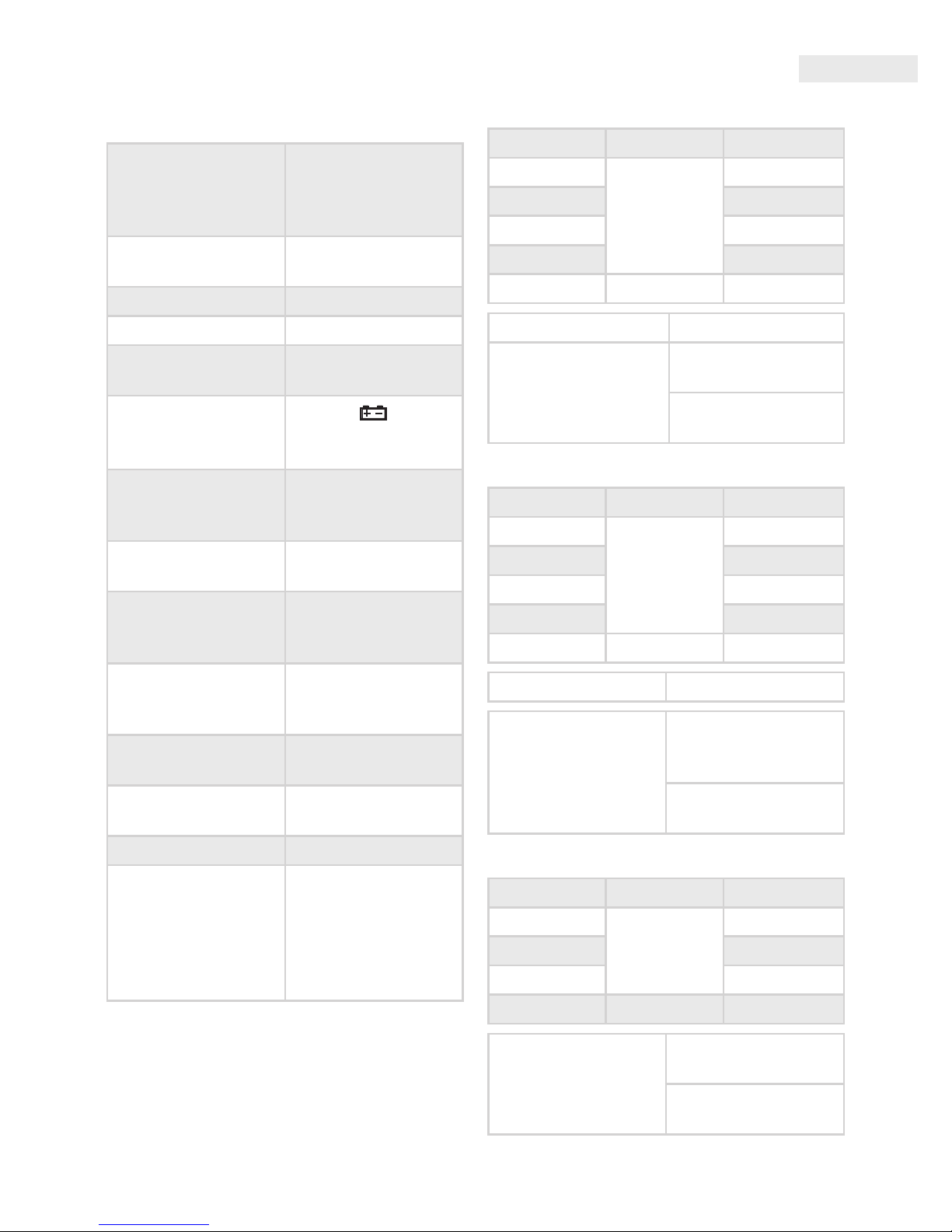
General description
Display
4 digit liquid crystal
display max. value
9999
Polarity
Automatic negative
polarity display
Nullication automatic
Measurement
process
A/D converter
Overload display only „OL” is displayed
Low battery power
The( ) symbol
appears on the screen
Safety
prescriptions
CE EMC/LVD. Device
complies to IEC1010
standard
Protection
category
II, double insulation
Operating
environment
temperature: 0…40
°C, relative humidity:
< 80%
Storage
environment
temperature: -20…60°C,
relative humidity:
< 80%
Battery 1 x 9V IEC 6F22 Battery
Dimensions
190 mm x 88,5 mm
x 27,5 mm
Weight 422 g (with battery)
Accesories
Instructions,
connection cable (red
and black, 1 pair),
hitting pocket
protector, K-type
thermometer probe
electrical
cHaracteristics
Accuracy +/- (% of displayed value + number of
digits) at 23 +/-5 °C, < 75% relative humidity
DCV
Range Accuracy Resolution
200 mV
+/- (0,5% + 3)
0,1 mV
2 V 1 mV
20 V 10 mV
200 V 100 mV
1000 V +/- (0,8% + 10) 1 V
Input
Impedance
10 MΩ
Overload
protection
(Range: 200 mV)
1000 VDC or AC peak
value
250 VDC or AC peak value
ACV
Range Accuracy Resolution
200 mV
+/- (0,8% + 5)
0,1 mV
2 V 1 mV
20 V 10 mV
200 V 100 mV
750 V +/- (1,2% + 10) 1 V
Input Impedance 10 MΩ
Frequency response
40 Hz - 1 KHz
(sine wave and
triangular wave)
40 Hz - 200 Hz
(other waves)
DCA
Range Accuracy Resolution
2 mA
+/- (0,8% +10)
1 μA
20 mA 10 μA
200 mA 100 μA
20 A +/- (2% + 5) 10 mA
Overload
protection
20 A / 250 V fuse with
"F" mark
200 mA / 250 V fuse with
"F" mark
Page 3
User Manual
EN
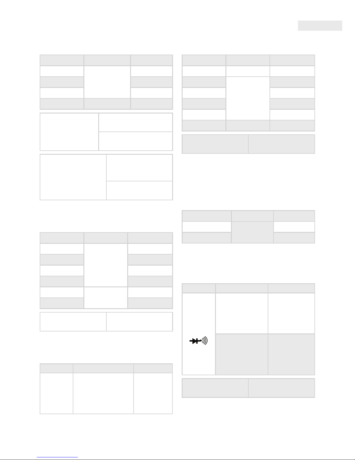
ACA
Range Accuracy Resolution
2 mA
+/- (0,8% + 10)
1 μA
20 mA 10 μA
200 mA 100 μA
20 A +/- (2% + 5) 10 mA
Overload
protection
20 A / 250 V fuse with
"F" mark
200 mA / 250 V fuse with
"F" mark
Frequency response
40 Hz - 1 KHz
(sine wave and
triangular wave)
40 Hz - 200 Hz
(other waves)
Capacitance
Range Accuracy Resolution
20 nF
+/- (3,5% + 20)
10 pF
200 nF 100 pF
2 μF 1 nF
20 μF 10 nF
200 μF
+/- (5% + 10)
100 nF
2000 μF 1 μF
Overload protection
DC 250V or AC peak
value
Transistor hFE-Test
Function Description Test state
h
FE
The amplication
factor of the transis-
tor is measured
(0-1000)
(NPN or PNP)
Base current
appr. 10 μA
VCE appr.
3 V
Resistance
Range Accuracy Resolution
200 Ω +/- (0,8% + 5) 0,1 Ω
2 kΩ
+/- (0,8% + 3)
1 Ω
20 kΩ 10 Ω
200 kΩ 100 Ω
2 MΩ 1 kΩ
20 MΩ
+/- (1,0% + 25)
10 kΩ
Overload protection
250 V DC or AC peak
value
The reading be displayed slowly when the
measurement is more than 1 MΩ. Please wait it to be
stable.
Temperature (with a K type temperature
sensor)
Range Accuracy Resolution
-20 °C - 1000 °C
+/- (1,5%+15)
1°C
0 °F - 1832 °F 1 °F
Diode and Continuity Testing
Function Reading Condition
Forward voltage
drop of diode
Forward DCA is
approx. 1 mA,
the backward
voltage is
approx. 3 V
Buzzer makes a
long sound while
resistance is less
than
70 Ω +/- 20 Ω
Opening volta-
ge appr. 3 V
Overload protection
250 V DC or AC peak
value
Page 4
EN
User Manual
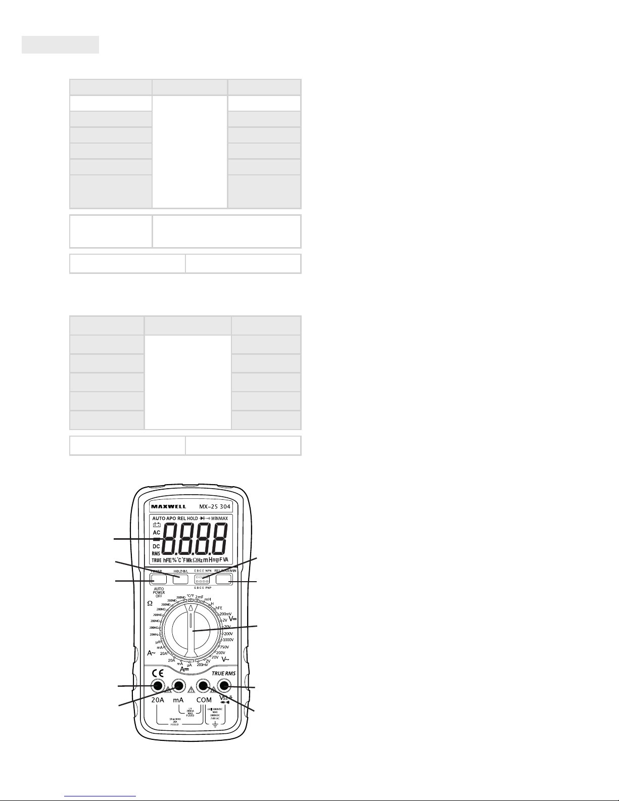
Frequency
Range Accuracy Resolution
10 Hz
+/-(0,1%+3)
0,01 Hz
100 Hz 0,1 Hz
1 kHz 1 Hz
10 kHz 10 Hz
100 kHz 100 Hz
1 MHz/10 MHz 1 kHz/10 kHz
Overload
protection
250 V DC or AC peak value
(for maximum 10 seconds)
Input sensitivity 1 V RMS
Inductance
Range Accuracy Resolution
2 mH
+/-(2,5%+30)
1 μH
20 mH 10 μH
200 mH 100 μH
2 H 1 mH
20 H 10 mH
Overload protection DC 36 V
Warning: Do not connect external voltage
source to the connectors!
1
2-2
2-1
7
6
5
4
3
2-4
2-3
1. LCD: display the measuring value and unit
2. Function keys
2-1. Power switch: turn on/o the power
2-2. Hold and backlight key: short press to the
measured value is held on LCD and "HOLD"
symbol displays. Press it again "HOLD" symbol
disappears and meter is exited the holding
mode. Long press to turn on/o the backlight.
2-3. Transistor test socket.
2-4. Press "REL/MAX/MIN", then you can test the
relative magnitude. If you hold the "REL/MAX/
MIN" for more than 2s, you can test the Max
and Min value.
3. Range knob: to select measuring function and
range.
4. Voltage, resistance, frequency, capacitance,
diode port - „V / Ω”
5. Common measuring port (COM)
6. Port for measuring current less than 200 mA
and inductivity
7. Port for measuring current 20 A
Usage
• Check the 9 V battery and press the "POWER"
button. If the battery is depleted, the battery
symbol appears on the screen.
• The signs near the connectors warn about not
exceeding the inward voltage or current. This is
to prevent damage to the inside circuits.
• Before measuring set the function switch to the
desired position.
• If you are unsure about the magnitude of the
result, set the switch to the highest possible
range and go backwards until you reach the
correct setting.
DC and AC voltage measuring
• Connect the black measuring wire to the „COM”,
and the red one to the „V / Ω” connector.
• Set the function switch to the correct "V"
position and connect the wires to the voltage
source paralelly.
Note:
• If you are unsure about the magnitude of the result, set the switch
to the highest possible range and go backwards until you reach
the correct setting.
• Set the DC / AC switch to the desired (DC or AC) function.
• If only an „OL” is displayed on the screen, it signals overload.
Switch to a higher range.
• Do not connect voltage exceeding DC 1000 V / AC 700 V to the
connectors. Results may be displayed at higher voltages also, but
this may lead to damage to the inside circuits.
• Do not touch the high voltage circuits while measuring.
Page 5
User Manual
EN
DC and AC current measuring
• Connect the black wire to the „COM” and the
red one to the „mA” connector (max. 200 mA)
or the „20A” connector for measuring 200 mA
or 20 A.
• Set the function switch to the proper range.
• Connect the the wires to the circuit serially.
• For measuring current between 200 mA and 20
A follow the instructions above, but connect
the red wire to the „20A” connector.
Note:
• If you are unsure about the magnitude of the result,
set the switch to the highest possible range and go
backwards until you reach the correct setting.
• If only an „OL” is displayed on the screen, it signals
overload. Switch to a higher range.
• The maximum inward current is 200 mA or 20 A
depending on the connector. (For maximum 15 seconds.)
Too much currency overheats the fuse which needs to be
replaced. The 20 A measuring range is not protected.
• Maximum overload voltage: 200 mV.
Resistance measuring
• Connect the black wire to the „COM”, and the red
one to the „V / Ω” connector.
• Set the function switch to the desired resistance
range.
• Touch the wires to the measured circuit paralelly.
Warning: make sure that the measured circuit is
not under power!
• The maximum overload capability for the
connector is 250 V RMS (for maximum 10
seconds).
Note:
• If the measured resistance value is over the maximum
threshold and the device signals overload („OL”), select a
higher range. When measuring above 1 MW it may take a
few seconds for the device to stabilize the displayed value.
This is completely normal for such resistors.
• If you do not connect a resistor to the connector (or there is
a break) the display will show „OL”.
• If you are measuring a resistor that is part of a circuit make
sure that the circuit is not under power and all capacitors are
discharged.
• Do not connect inward voltage to the device as it may lead to
damage to the inside circuits.
• The outward voltage on connectors not under power is
approximately 3 V.
Capacity measuring
• Set the function switch to "2 mF" position.
• Connect the measured capacitor to the „V /
Ω” and "COM" connector. Pay attention to the
correct polarity.
Note:
• If the measured value exceeds the maximum value of the
selected range and the device signals overload („OL”).
• Unit: 1 nF=10
-3
μF or 1000 pF
• Do not connect external voltage or current to the connector!
Turn o the power and discharge the capacitors before
measuring. Also discharge the electrolyte capacitors before
measuring!
• Before measuring discharge the electrolyte capacitors
more times.
Diode and continuity test
• Connect the black measuring wire to the
„COM”, the red one to „V / Ω” connector. (Note:
the polarity of the red wire is: +)
• Set the function to „ ” position.
• Touch the wires to the diode's connectors.
The screen shows the opening voltage of the
diode.
• Connect the wires to two points of the circuit. If
the resistance is below 90 Ω the device beeps.
Note:
• If you do not connect a unit to the connectors (or there is a
break) the display will show „OL”.
• During the test 1 mA current goes through the diode.
• The display shows the opening voltage of the diode in mV,
and overload if the diode is connected with the polarity
reversed
Temperature measuring
• Set the function switch to "°C/°F" position.
• Connect the black wire of the temperature
measuring sensor to the „COM” connector and
the red one to the „V/Ω” connector. Put the
sensor to the place measured. The display shows
the measured value in °C or °F (press "HOLD"
button to select).
Note:
• The device functions with a special temperature measuring
sensor.
• If the sensor is not connected to the connector, the device
displays the temperature of the environment.
• Do not connect outward voltages to the connectors, if the
device is in temperature measuring function.
Transistor hFE test
• Set the function switch to "hFE" position.
• Determine if the transistor is NPN or PNP and
place it in the proper connector.
• The amplication factor of the transistor is
displayed on the screen.
• IB = 10 μA, VCE = 2,8 V
Page 6

EN
User Manual
Frequency measuring
• Connect the measuring wire or the shielded
cable to the „COM” and „V / Ω” connectors.
• Set the function switch to „20MHz” position
and touch the wires to the signal source.
Note:
• Do not measure frequency at a voltage exceeding 250
V(RMS).
• In noisy environment it is advised to use a shielded cable for
measuring small values.
• Avoid touching the circuit when measuring high voltage!
• Frequency measuring changes range automatically.
Inductance measuring
• Set the function swith to the desired measuring
range.
• Connect the measured inductor to the "mA"
and "COM" terminal.
Remark:
• If the measured inductance is not known, start measuring
at H range until overload signal turns o.
• Inductors with low inductance function as short circuits. If
possible, do not connect such inductors to the connectors.
Auto Power O
• After stop working for 15 minutes, the meter
will be into sleep mode. Press "POWER" key can
back to work.
• Press "REL/MAX/MIN" key and at the same time
with the "POWER" key the "APO" symbol will
disappear, now you already closed the function
of auto power o.
WarninG
• When measuring voltage make sure that the
wires are not connected to a current measuring
connector and that the function switch is not
in resistance or diode measuring measuring
mode. Always check if you have connected the
wires into the proper connectors.
• Be careful when measuring voltage above 50 V,
especially with high voltage equipment.
• Avoid connecting to „live” circuits.
• Turn o the power in the circuit before
connecting the multimeter to measure current
and do not measure above 20 A.
• Before measuring resistance and diode make
sure the circuit is not under power.
• Always set the function and measuring range
appropriate for the measuring. If in doubt,
set the maximum measuring range and go
backwards.
• Make sure that the wire and its isolation is not
damaged.
• Only replace fuses to the same type and value.
• When replacing the fuse or battery make sure
all external power sources are turned o and
that the multimeter is turned o as well.
care and maintenance
Operation
• Keep the multimeter dry. If it gets wet, dry it up
immediately. The liquid corrodes the electric
circuit.
• The multimeter should be stored and used
only at normal temperature. High temperature
can shorten the lifetime of electronic devices,
damage to the batteries and distort, melt the
plastic parts.
• Handle the multimeter carefully. If it is dropped
that can cause damage to the electric circuit
and to the case which leads to the improper
operation of the multimeter.
• Keep away the multimeter from dust and
dirt which results in premature wear of the
components.
• The multimeter can be cleaned with wet
cloth. Do not use chemicals, solvents or strong
detergents for cleaning.
• Servicing
• Battery replacement (1 piece 9V)
• Turn o all external circuits. Switch o the
multimeter and pull out the test lead of the
socket.
• Unscrew the screws and remove the bottom
cover.
• Remove the low battery and replace a same
type of it.
Fuse replacement
• Turn o all external circuits. Set the switch to
OFF position and pull out the test lead of the
socket.
• Unscrew the screws and remove the bottom
cover.
• Replace the blown out fuse to a same type and
valued (5x20 mm, 200 mA / 250 V „F” signed.)
Page 7
Használati utasítás
HU
általános leírás
Kijelző
4 digites
folyadékkristályos
max. kijelezhető érték
9999
Polaritás
automatikus negatív
polaritás kijelzés
Nullázás automatikus
Mérési eljárás A/D konverter
Túlterhelés kijelzés
csak az „OL” felirat
látható
Alacsony
telepfeszültség
az elem( )
szimbólum
megjelenik a kijelzőn
Biztonsági előírás
CE EMC/LVD. A
műszer megfelel az
IEC1010 szabványnak
Érintésvédelmi
osztály
II. Kettős szigetelésű
Üzemi környezet
hőmérséklet (relatív
páratartalom)
0-40 °C (< 80%)
Tárolási környezet
hőmérséklet (relatív
páratartalom)
-20 °C- +60 °C (< 80%)
Elem
1 db 9V-os IEC 6F22
típusú elem
Méretek
190 mm x 88,5 mm x
27,5 mm
Tömeg 422 g (elemmel)
Tartozékok
használati utasítás,
műszerzsinór (piros
és fekete,1 pár),
ütésvédő tok, K
tipusú hőmérő
szonda
elektromos jellemzők
A pontosság +/- (kijelzett érték %-a + digitek
száma) 23 +/-5 °C-on, 75%-nál kisebb relatív
páratartalom esetén
DCV
Méréshatár Pontosság Felbontás
200 mV
+/- (0,5% + 3)
0,1 mV
2 V 1 mV
20 V 10 mV
200 V 100 mV
1000 V +/- (0,8% + 10) 1 V
Impedancia 10 MΩ
Túlterhelés elleni
védelem
(tartomány: 200 mV)
1000 VDC vagy AC
csúcsérték
250 VDC vagy AC
csúcsérték
ACV
Méréshatár Pontosság Felbontás
200 mV
+/- (0.8% + 5)
0,1 mV
2 V 1 mV
20 V 10 mV
200 V 100 mV
750 V +/- (1.2% + 10) 1 V
Impedancia 10 MΩ
Frekvenciaátvitel
40 Hz - 1 KHz
(szinuszjel és
háromszögjel)
40 Hz - 200 Hz
(egyéb jel)
DCA
Méréshatár Pontosság Felbontás
2 mA
+/- (0,8% + 10)
1 μA
20 mA 10 μA
200 mA 100 μA
20 A +/- (2% + 5) 10 mA
Túlterhelés elleni
védelem
20 A / 250 V
"F" jelzésű biztosíték
200 mA / 250 V
"F" jelzésű biztosíték
Page 8

HU
Használati utasítás
ACA
Méréshatár Pontosság Felbontás
2 mA
+/- (0,8% + 10)
1 μA
20 mA 10 μA
200 mA 100 μA
20 A +/- (2% + 5) 10 mA
Túlterhelés elleni
védelem
20 A / 250 V
"F" jelzésű biztosíték
200 mA / 250 V
"F" jelzésű biztosíték
Frekvenciaátvitel
40 Hz - 1 KHz
(szinuszjel és
háromszögjel)
40 Hz - 200 Hz
(egyéb jel)
Kapacitás
Méréshatár Pontosság Felbontás
20 nF
+/- (3,5% +20)
10 pF
200 nF 100 pF
2 μF 1 nF
20 μF 10 nF
200 μF
+/- (5% + 10)
100 nF
2000 μF 1 μF
Túlterhelés elleni
védelem
250 VDC vagy AC
csúcsérték
Tranzisztor hFE teszt
Funkció Leírás
Teszt
állapot
h
FE
A tranzisztor
áramerősítési
tényezőjét méri
(0-1000)
(NPN vagy PNP)
Bázisáram
kb. 10 μA
VCE kb. 3 V
Ellenállás
Méréshatár Pontosság Felbontás
200 Ω +/- (0,8% + 5) 0,1 Ω
2 kΩ
+/- (0,8% + 3)
1 Ω
20 kΩ 10 Ω
200 kΩ 100 Ω
2 MΩ 1 kΩ
20 MΩ +/- (1,0% +25) 10 kΩ
Túlterhelés elleni
védelem
250 VDC vagy AC
csúcsérték
1 MΩ-nál nagyobb mérés esetén az érték
lassabban jelenik meg a kijelzőn. Kérjük várjon,
amig stabilizálódik.
Hőmérséklet (K típusú hőmérsékletmérő szenzorral)
Méréshatár Pontosság Felbontás
-20 °C – 1000 °C
+/-(1,5%+15)
1°C
0 °F – 1832 °F 1°F
Dióda teszt
Funkció Leírás Teszt állapot
A dióda
nyitófeszültségét
méri
Nyitóirányú DC
áram kb. 1 mA
Záró irányú DC
feszültség kb.
3 V
Sípoló hang jelzi,
ha az ellenállás
kisebb, mint
70 Ω +/- 20 Ω
Nyitófeszültség
kb. 3 V
Túlterhelés elleni
védelem
250 VDC vagy AC
csúcsérték
Page 9

Használati utasítás
HU
Frekvencia
Méréshatár Pontosság Felbontás
10 Hz
+/-(0,1%+3)
0,01 Hz
100 Hz 0,1 Hz
1 kHz 1 Hz
10 kHz 10 Hz
100 kHz 100 Hz
1 MHz/10 MHz 1 kHZ/10 Khz
Túlterhelés elleni
védelem
250 VDC vagy AC
csúcsérték
(maximum 10 mp-ig)
Érzékenység 1 V RMS
Induktivitás
Méréshatár Pontosság Felbontás
2 mH
+/-(2,5%+30)
1 μH
20 mH 10 μH
200 mH 100 μH
2 H 1 mH
20 H 10 mH
Túlterhelés elleni
védelem
DC 36 V
Figyelmeztetés: Ne csatlakoztasson a
kapcsokra külső feszültségforrást!
1
2-2
2-1
7
6
5
4
3
2-4
2-3
1. LCD: kijelzi a mért értéket és a mértékegységet
2. Funkció kapcsoló
2-1. Ki/be kapcsoló gomb
2-2. Adattartás és háttérvilágítás gomb: röviden
megnyomva az éppen mért értéket tartja meg
a kijelzőn, eközben "HOLD" felirat látható.
2-3. Tranzisztor teszt aljzat.
2-4. Nyomja meg a "REL/MAX/MIN" gombot
a relatív mérésmódhoz. Ezt a gombot hosszan
nyomva (kb. 2 mp) a maximális vagy a
minimális mért érték érhető el.
3. Forgókapcsoló: a mérési mód és a méréshatár
változtatható vele.
4. Feszültség, ellenállás, frekvencia, kapacitás és
dióda mérés aljzat - „V / Ω”
5. Közös aljzat (COM)
6. 200 mA és induktivitás mérő aljzat
7. 20 A mérő aljzat
Használat
• Ellenőrizze a 9 V-os elemet, majd nyomja
be hosszan a "POWER" gombot be/
kikapcsoláshoz. Ha az elem lemerült, az
szimbólum megjelenik a kijelzőn.
• Az aljzatok melletti jelzések gyelmeztetnek,
hogy a bemenő feszültség vagy áram ne haladja
meg a jelzett értéket. Így megakadályozhatja a
belső áramkörök sérülését.
• A funkcióválasztó kapcsolót a mérés előtt állítsa
a megfelelő állásba (funkcióhoz)
• Ha a mérendő mennyiség nagyságrendjét
nem ismeri, állítsa a kapcsolót a legmagasabb
méréshatárra és onnan haladjon visszafelé,
amíg a megfelelő értéket eléri.
DC és AC feszültség mérése
• Csatlakoztassa a fekete csatlakozót a „COM”, a
piros csatlakozót a „V / Ω” aljzatba.
• Állítsa a funkcióválasztó kapcsolót a megfelelő
"V" pozícióba és csatlakoztassa a tapogatókat
párhuzamosan a feszültségforrással a mérés
idejére.
Megjegyzés:
• Ha a mérendő mennyiség nagyságrendjét nem ismeri,
állítsa a kapcsolót a legmagasabb méréshatárra és onnan
haladjon visszafelé, amíg a megfelelő értéket eléri.
• Állítsa a DC / AC kapcsolót a megfelelő (DC vagy AC)
módba.
• Ha csak az „OL” látható a kijelzőn, az a túlterhelést
jelzi. Ilyenkor kapcsolja a funkciókapcsolót magasabb
méréshatárba.
Page 10

HU
Használati utasítás
• Ne kapcsoljon DC 1000 V / AC 700 V-nál magasabb
feszültséget a bemenetre. A kijelzés lehetséges magasabb
feszültségeken is, de ez a belső áramkörök sérüléséhez
vezethet.
• Ne érintse a nagyfeszültségű áramköröket mérés közben.
DC és AC áram mérése
• Csatlakoztassa a fekete vezetéket a „COM”, a
piros vezetéket pedig a „mA” (max. 200 mA)
vagy „20A” jelzésű aljzatba, 200 mA-es illetve
20 A-es méréshez.
• Állítsa a funkció kapcsolót a megfelelő
méréshatárhoz.
• Csatlakoztassa a tapogatókat sorosan az
áramforrással a méréshez.
• 200 mA és 20 A közötti áram méréséhez az
előző pontokat kövesse, de a piros mérőzsinórt
a „20A” jelzésű aljzatba csatlakoztassa.
Megjegyzés:
• Ha a mérendő áram nagyságrendjét nem ismeri, állítsa
a kapcsolót a legmagasabb méréshatárra és onnan
haladjon visszafelé, amíg a megfelelő értéket eléri.
• Ha csak az „OL” látható a kijelzőn, az a túlterhelést
jelzi. Ilyenkor kapcsolja a funkciókapcsolót magasabb
méréshatárba.
• A maximális bemenő áram 200 mA vagy 20 A a választott
bemenettől függően. (A teszt ideje max. 15 másodperc.)
A túl nagy áramerősség a biztosítékot kiolvasztja, amit ki
kell cserélni. A 20 A-es méréshatár nincs biztosítva.
• Maximális terhelőfeszültség: 200 mV.
Ellenállásmérés
• Csatlakoztassa a fekete vezetéket a „COM”, a piros
vezetéket pedig a „V / Ω” aljzatba.
• Állítsa a funkciókapcsolót a kívánt ellenállás
méréshatárra.
• Érintse a mérőhegyeket a mérendő áramkörhöz, de
azzal párhuzamosan. Figyelmeztetés: biztosítsa
a mérendő áramkör feszültségmentességét!
• A bemenet maximális túlterhelhetősége: 250 V
RMS (max. 10 másodpercig).
Megjegyzés:
• Ha a mérendő ellenállás értéke meghaladja a méréshatár
maximális értékét, és a műszer túlterhelést jelez („OL”),
válasszon egy magasabb méréshatárt. 1 MW fölötti
ellenállásoknál a műszer néhány másodperc alatt
stabilizálja a kijelzett értéket. Ez teljesen normális nagy
értékű ellenállások mérésénél.
• Ha a bemenetre nem csatlakoztat ellenállást (pl. szakadás),
a kijelzőn az „OL” felirat jelenik meg a méréshatár túllépés
miatt.
• Ha áramkörben lévő ellenállást vizsgál, biztosítsa, hogy
a teszt alatt az áramkör feszültségmentes legyen, és a
kondenzátorok legyenek kisütve.
• Ne kapcsoljon a műszerre bemenő feszültséget, mert az a
belső áramkörök sérüléséhez vezethet.
• Terheletlen kapcsokon a kimeneti feszültség kb. 3 V.
Kapacitásmérés
Állítsa a funkcióválasztó kapcsolót a "2 mF" állásba.
Csatlakoztassa a kondenzátort a "V/Ω" és "COM"
jelű aljzatba a műszerzsinórok segítségével,
ügyelve a helyes polaritásra, amikor szükséges.
Megjegyzés:
• Ha a mérendő kondenzátor értéke meghaladja a
méréshatár maximális értékét, és a műszer túlterhelést
jelez („OL”).
• Mértékegység: 1 nF=10
-3
μF vagy 1000 pF
• Ne csatlakoztasson külső feszültséget vagy áramot az
aljzatba. Mérés előtt kapcsolja ki a tápfeszültséget és a
kondenzátorokat süsse ki.
• Mérés előtt az elektrolit kondenzátorokat többször süsse ki
egymás után.
Dióda és folytonosság teszt
• Csatlakoztassa a fekete műszerzsinórt a „COM”,
a pirosat a „V/Ω” aljzatba. (Megjegyzés: a piros
tapogató polaritása: +)
• Állítsa a funkció kapcsolót a állásba.
• Érintse a tapogatókat a dióda kivezetéseihez. A
kijelzőn a dióda nyitófeszültsége látható.
• Érintse a tapogatókat az áramkör két pontjára.
Sípoló hang jelez, ha az ellenállás kisebb 90 Ω-nál.
Megjegyzés:
• Ha a bemenetre nem csatlakoztat alkatrészt (pl. szakadás),
a kijelzőn az „OL” felirat jelenik meg.
• A diódán 1 mA áram folyik a teszt alatt.
• A kijelzőn a dióda nyitófeszültsége olvasható mV-
ban, és túlterhelés, ha a diódát fordított polaritással
csatlakoztatta.
Hőmérséklet mérés
• Állítsa a funkciókapcsolót a "°C/°F" állásba
• Helyezze a hőmérsékletmérő szonda fekete
csatlakozóját a „COM” jelű aljzatba, a piros
csatlakozót pedig a „V/Ω” aljzatba. Az érzékelőt
helyezze a mérendő hőmérsékletű helyre.
A kijelzőn a mért hőmérséklet olvasható °C
vagy °F-ban (nyomja meg a "HOLD" gombot a
mértékegység választáshoz).
Megjegyzés:
• A műszer speciális hőmérséklet-mérő szondával működik.
• Ha a szondát nem csatlakoztatjuk az aljzatba, akkor a
műszer a környezete hőmérsékletét mutatja.
• Ne kapcsoljon a bemenetekre külső feszültséget, ha a
műszer hőmérséklet-mérő állásban van.
Tranzisztor hFE teszt
• Állítsa a funkciókapcsolót a "hFE" állásba
• Határozza meg, hogy a tranzisztor NPN vagy
PNP, és helyezze az alkatrészt a lábkiosztásának
megfelelő csatlakozóba.
• A kijelzőről a tranzisztor áram-erősítési
tényezője olvasható le. IB = 10 μA, VCE = 2,8 V
Page 11

Használati utasítás
HU
Frekvenciamérés
• Csatlakoztassa a műszerzsinórt vagy az
árnyékolt kábelt a „COM” és a „V/Ω” aljzatokba.
• Állítsa a funkciókapcsolót „20MHz” állásba és
érintse a tapogatókat a jelforráshoz.
Megjegyzés:
• Ne mérjen 250 V(RMS)nál nagyobb feszültségen
frekvenciát.
• Zajos környezetben célszerű árnyékolt kábelt használni kis
jelek mérésénél.
• Nagyfeszültségű mérésnél kerülje az áramkör érintését.
• A frekvenciamérés automata méréshatár-váltós.
Induktivitás (L) mérés
Állítsa a funkciókapcsolót a kívánt induktivitás
méréshatárba.
Csatlakoztassa a mérendő tekercset az "mA" és
"COM" aljzatokba.
Megjegyzés:
• Ha a tekercs induktivitása nem ismert, kezdje a mérést a H
méréshatárnál.
Auto Power O
• Használat után 15 perccel a műszer készenléti
üzemmódra vált. A "POWER" gomb
megnyomásával a műszer újra használható.
• Nyomja meg a "REL/MAX/MIN" gombot egy
időben a "POWER" gombbal és az "APO"
felirat eltűnik a kijelzőről. Ezzel az automata
kikapcsolás funkció inaktív lesz.
FiGyelmeztetés
• Feszültség mérésénél biztosítsa, hogy a vezetékek
ne csatlakozzanak árammérő aljzathoz és a
funkciókapcsoló ne legyen ellenállás vagy dióda
ellenőrző állásban. Mindig ellenőrizze, hogy
a mérendő mennyiségnek megfelelő aljzatba
csatlakoztatta-e a vezetéket.
• Legyen körültekintő 50 V-nál nagyobb
feszültség mérésekor, különösen erősáramú
berendezéseknél.
• Kerülje az „élő” áramkörökhöz való csatlakozást.
• Árammérésnél az áramkört feszültségmentesítse,
mielőtt csatlakoztatná hozzá a multimétert. Ne
mérjen 20 A-nél nagyobb áramot.
• Ellenállásmérés és dióda tesztelés
előtt gondoskodjon az áramkör
feszültségmentesítéséről a mérés idejére.
• Mindig a mérésnek megfelelő funkciót és
méréshatárt válassza. Ha kétséges a mérendő
mennyiség nagyságrendje, válassza a
legmagasabb méréshatárt és onnan haladjon
visszafelé.
• Győződjön meg a műszerzsinór hibátlan
állapotáról, a szigetelés sértetlenségéről.
• Biztosítékot csak azonos típusúra és értékűre
cseréljen.
• Biztosíték- vagy elemcserénél a műszer tokjának
kinyitása előtt kapcsoljon le minden külső
áramkört és kapcsolja ki a multimétert.
kezelés és karbantartás
Kezelés
• Tartsa a multimétert szárazon. Ha nedvesség
éri, törölje le azonnal. A folyadékok korrodálják
az áramköröket.
• A multimétert tárolni és használni csak normál
hőmérsékleten szabad. A magas hőmérséklet
rövidíti az elektronikus eszközök élettartamát,
megrongálja az elemeket, és eltorzítja,
megolvasztja a műanyag alkatrészeket.
• Bánjon óvatosan és gondosan a multiméterrel.
Az elejtés kárt tesz az áramkörökben és a
tokban, ami a multiméter helytelen működését
okozza.
• Óvja a multimétert a portól és egyéb
szennyeződésektől, amik az alkatrészek idő
előtti kopását eredményezik.
• A multimétert nedves ruhával tisztíthatja. Ne
alkalmazzon vegyszereket, oldószereket vagy
erős tisztítószereket a tisztításhoz.
Karbantartás
• Elemcsere (1 db 9V-os)
• Kapcsoljon le minden külső áramkört a
műszerről. Kapcsolja ki a multimétert és a
műszerzsinórt húzza ki az aljzatból.
• Csavarja ki a csavarokat és emelje le az alsó
fedelet.
• Távolítsa el a lemerült elemet és cserélje ki
ugyanolyan típusúra.
biztosítékcsere
• Kapcsoljon le minden külső áramkört a
műszerről. Állítsa a funkciókapcsolót OFF
állásba és a műszerzsinórt húzza ki az aljzatból.
• Csavarja ki a csavarokat és emelje le az alsó
fedelet.
• Cserélje ki a kiolvadt biztosítékot ugyanolyan
típusúra és értékűre. (5x20 mm, 200 mA / 250
V „F” jelzésű.)
Page 12

RO
Manual de utilizare
descriere Generală
Aşaj
LCD cu 4 cifre aşare
max. 9999
Polaritate
aşare automată de
polaritate negativă
Calibrare 0 automatică
Metoda de
măsurare
convertor A/D
Aşare suprasarcină doar „OL” se vede
Baterie descărcată
simbolul( )apare
pe aşaj
Norme de securitate
CE EMC/LVD. Aparatul
corespunde normelor
IEC1010
Clasa de protecţie II. Izolaţie dublă
Mediu de lucru
Temp
(Umiditate relativă)
0-40 °C (< 80%)
Mediu de stocare
Temp
(Umiditate relativă)
-20 °C- +60 °C (< 80%)
Baterie 1 buc 9V tip IEC 6F22
Dimensiuni
190 mm x 88,5 mm
x 27,5 mm
Greutate 422 g (cu baterie)
Accesorii
manual de utilizare,
cabluri de măsurat
(roşu şi negru, 1 per),
husă antişoc, sondă
termometrică tip K
caracteristici electrice
Acurateţea +/- (% valorii aşate + nr. cifrelor) a
fost stabilită la 23 +/-5 °C, la umiditate relativă
< 75%
Tensiune DC
Domeniu Acurateţe Rezoluţie
200 mV
+/- (0,5% + 3)
0,1 mV
2 V 1 mV
20 V 10 mV
200 V 100 mV
1000 V +/- (0,8% +10) 1 V
Impedanţa 10 MΩ
Protecţie la
suprasarcină
(domeniu: 200 mV)
1000 V CC sau CA
valoare de vârf
230V CC sau CA
valoare de vârf
Tensiune AC
Domeniu Acurateţe Rezoluţie
200 mV
+/- (0.8% + 5)
0,1 mV
2 V 1 mV
20 V 10 mV
200 V 100 mV
750 V +/- (1.2% +10) 1 V
Impedanţa 10 MΩ
Banda de frecvenţă
40 Hz - 1 KHz
(semnal sinusoidal
sau triunghiular)
40 Hz - 200 Hz
(alte semnal)
Curent DC
Domeniu Acurateţe Rezoluţie
2 mA
+/- (0,8% +10)
1 μA
20 mA 10 μA
200 mA 100 μA
20 A +/- (2% + 5) 10 mA
Protecţie la
suprasarcină
20 A / 250 V
fuzibil tip "F"
200 mA / 250 V
fuzibil tip "F"
Page 13

Manual de utilizare
RO
Curent AC
Domeniu Acurateţe Rezoluţie
2 mA
+/- (0,8% +10)
1 μA
20 mA 10 μA
200 mA 100 μA
20 A +/- (2% + 5) 10 mA
Protecţie la
suprasarcină
20 A / 250 V
fuzibil tip "F"
200 mA / 250 V
fuzibil tip "F"
Frekvenciaátvitel
40 Hz - 1 KHz
(semnal sinusoidal
sau triunghiular)
40 Hz - 200 Hz
(alte semnal)
Capacitate
Domeniu Acurateţe Rezoluţie
20 nF
+/- (3,5% + 20)
10 pF
200 nF 100 pF
2 μF 1 nF
20 μF 10 nF
200 μF
+/- (5% + 10)
100 nF
2000 μF 1 μF
Protecţie la
suprasarcină
250 V CC sau CA
valoare de vârf
Test tranzistor hFE
Funcţia Descriere Stare test
h
FE
Măsoară
coecientul
de amplicare
în curent al
tranzistorului
(0-1000)
(NPN - PNP)
Curent
bazic cca.
10 μA
VCE cca. 3 V
Rezistenţă
Domeniu Acurateţe Rezoluţie
200 Ω +/- (0,8% + 5) 0,1 Ω
2 kΩ
+/- (0,8% + 3)
1 Ω
20 kΩ 10 Ω
200 kΩ 100 Ω
2 MΩ 1 kΩ
20 MΩ +/- (1,0% +25) 10 kΩ
Protecţie la
suprasarcină
250 V CC sau CA
valoare de vârf
La măsurarea valorilor de peste 1 Mohm,
valoare se aşează mai lent. Vă rugăm aşteptaţi
stabilizarea valorii.
Temperatură (cu sensor termometric tip K)
Domeniu Acurateţe Rezoluţie
-20 °C – 1000 °C
+/-(1,5%+15)
1°C
0 °F – 1832 °F 1°F
Diode test
Funcţia Descriere Stare test
Măsoară
tensiunea de
deschidere al
diodei
Curent DC
direct cca. 1 mA
Tensiune DC
invers cca. 3 V
Piuit
semnalizează
dacă între V/
Ohm şi COM
rezistenţa este
mai mică de
70 Ω +/- 20 Ω
Tensiunea de
deschidere cca.
3 V
Protecţie la
suprasarcină
250 V CC sau CA
valoare de vârf
Page 14

RO
Manual de utilizare
Frecvenţă
Domeniu Acurateţe Rezoluţie
10 Hz
+/-(0,1%+3)
0,01 Hz
100 Hz 0,1 Hz
1 kHz 1 Hz
10 kHz 10 kHz
100 kHz 100 kHz
1 MHz/10 MHz 1 kHz/10 kHz
Protecţie la
suprasarcină
250 V CC sau CA
valoare de vârf
(max. 10 secunde)
Sensibilitate 1 V RMS
Inductivitate
Domeniu Acurateţe Rezoluţie
2 mH
+/-(2,5%+30)
1 μH
20 mH 10 μH
200 mH 100 μH
2 H 1 mH
20 H 10 mH
Protecţie la
suprasarcină
DC 36 V
Atenţie: Nu conectaţi la borne sursă de
tensiune exterioară!
1
2-2
2-1
7
6
5
4
3
2-4
2-3
1. Aşaj LCD indică valoarea măsurată şi unitatea
de măsură
2. Comutator funcţii
2-1. Buton On-O
2-2. Buton HOLD şi iluminare fundal:
apăsând scurt incrementează pe aşaj
valoare măsurată şi apare simbolul „HOLD”
2-3. Soclu test tranzistoare.
2-4. Apăsaţi butonul "REL/MAX/MIN" pt.
măsurarea relativă.. Apăsând lung (cca. 2
sec.) se obţine valoarea maximă sau minimă.
3. Comutator rotativ: selectare mod şi domeniu
de măsurare.
4. Mufă de măsurare tensiune, rezistenţă,
frecvenţă, capacitate şi test diodă - „V / Ω”.
5. Mufă comună (COM)
6. Mufă 200mA şi inductivitate
7. Mufă 20A
Utilizare
• Vericaţi bateria de 9 V, comutaţi butonul
"POWER" la poziţia ON. Dacă bateria s-a
descărcat simbolul apare pe aşaj.
• Semnele lângă bananele de conectare vă
avertizează să nu depăşească tensiunea sau
curentul de intrare nivelurile aşate. Astfel
puteţi evita deteriorarea circuitelor din interior.
• Înainte de măsurare comutatorul de funcţii
comutaţi la poziţia corectă (la funcţia dorită).
• Dacă nu cunoaşteţi domeniul nivelului valorii
ce doriţi a măsura, selectaţi domeniul cel mai
mare cu comutatorul de funcţii şi de acolo să
reveniţi la domeniu de măsurare mai mică până
atingeţi nivelul dorit.
Măsurare tensiune DC şi AC
• Conectaţi cablul de măsurare negru la „COM”,
iar cel roşu la „V/Ω”.
• Comutaţi selectorul de funcţii la poziţia "V"
potrivit şi conectaţi tentaculele în paralel cu
sursa de tensiune pe timpul măsurării.
Notă:
• Dacă nu cunoaşteţi domeniul nivelului valorii ce doriţi a
măsura, selectaţi domeniul cel mai mare cu comutatorul
de funcţii şi de acolo să reveniţi la domeniu de măsurare
mai mică până atingeţi nivelul dorit.
• Comutaţi comutatorul DC/AC la modul (DC sau AC) dorit.
• Dacă pe aşaj apare doar „OL”, aparatul vă indică
suprasarcină. În acest caz comutaţi la domeniu de măsurat
mai mare.
• Nu conectaţi la intrare tensiune mai mare de DC 1000 V/
AC 700 V. Aşarea este posibilă şi la tensiuni mai mari dar
riscaţi integritatea circuitelor interioare.
Page 15

Manual de utilizare
RO
• Nu atingeţi circuitele de înaltă tensiune în timpul
măsurării.
Măsurare curent DC şi AC
• Conectaţi cablul de măsurare negru la „COM”,
iar cel roşu la „mA” (max. 200 mA) sau la „20A”,
pentru măsurare până la 200 mA respectiv 20 A.
• Aşezaţi comutatorul de funcţii la domeniul de
măsurat corespunzător.
• Conectaţi tentaculele în serie cu sursa de curent
pentru măsurare.
• Pentru măsurarea curentului între 200 mA şi
20 A urmaţi punctele de mai sus, dar cablul de
măsurat roşu conectaţi la „20A”.
Notă:
• Dacă nu cunoaşteţi domeniul nivelului valorii ce doriţi a
măsura, selectaţi domeniul cel mai mare cu comutatorul
de funcţii şi de acolo să reveniţi la domeniu de măsurare
mai mică până atingeţi nivelul dorit.
• Dacă pe aşaj apare doar „OL”, aparatul vă indică
suprasarcină. În acest caz comutaţi la domeniu de
măsurat mai mare.
• Curentul maxim de intrare este 200 mA sau 20 A în funcţie
de banana de intrare aleasă. (Timpul testului este max.
15 secunde.) Curentul prea mare topeşte fuzibilul care
pe urmă trebuie schimbat. Domeniul 20 A nu are fuzibil.
• Tensiunea de sarcină maximă: 200 mV.
Măsurare rezistor
• Conectaţi cablul de măsurare negru la „COM”,
„V/ Ω”.
• Aşezaţi comutatorul de funcţii la domeniul de
rezistenţă dorită.
• Atingeţi vârfurile tentaculelor la
circuitul de măsurat dar în paralel cu el.
Atenţie: asiguraţi-vă ca circuitul de măsurat să e
scos de sub tensiune.
• Sarcina maximă de intrare: 250 V RMS (max. 10
secunde).
Notă:
• Dacă valoarea rezistenţei măsurate depăşeşte nivelul
maxim al domeniului de măsurat ales, şi aparatul indică
suprasarcină („OL”), alegeţi un domeniu de măsurat mai
mare. La rezistoare peste 1 MΩ aparatul are nevoie de
câteva secunde până la stabilirea valorii măsurate. Acest
lucru este absolut normal la măsurarea rezistoarelor de
valoare mare.
• Dacă nu conectaţi rezistor la tentaculele aparatului
(ex. ruptură), pe aşaj apare „OL” indicând depăşirea
domeniului de măsurat.
• Dacă testaţi rezistor în circuit, asiguraţi-vă să e circuitul
scos de sub tensiune pe timpul testului şi condensatoarele
să e descărcate.
• Nu conectaţi la aparat tensiune de intrare, întrucât puteţi
deteriora circuitele aparatului.
• Pe bornele fără sarcină tensiunea de ieşire este cca. 3 V.
Măsurare capacitate
• Aşezaţi comutatorul de funcţii în poziţia
"2 mF".
· Conectaţi condensatorul la mufele "V/Ω"
şi "COM" cu ajutorul cablurilor de măsurare,
respectând polaritatea, dacă este cazul.
Notă:
• Dacă valoarea condensatorului ce va măsurat depăşeşte
nivelul maxim al domeniului de măsurat ales şi aparatul
indică suprasarcină („OL”).
• Unitate de măsură: 1 nF=10-3 μF sau 1000 pF
• Nu conectaţi tensiune sau curent exterior în bornă.
Înainte de măsurare opriţi sursa şi condensatoarele să le
descărcaţi.
• Înainte de măsurare condensatoarele electrolitice să le
descărcaţi de mai multe ori. (Scurtcircuitaţi picioarele
condensatorului timp de 10-20 sec., pe urmă măsuraţi
tensiune la picioarele condensatorului, asigurându-vă că
aţi reuşit să descărcaţi condensatorul)
Test diode şi continuitate
• Conectaţi cablul de măsurare negru la „COM”,
iar cel roşu la „V/Ω”. (Notă: tentaculul roşu are
polaritatea: +)
• Aşezaţi comutatorul de funcţii la poziţia .
• Atingeţi tentaculele la terminalele diodei. Pe aşaj
se citeşte tensiunea de deschidere al diodei.
• Atingeţi tentaculele la 2 puncte dorite în circuit.
Piuit semnalizează dacă rezistenţa este mai
mică de 90 Ω.
Notă:
• Dacă la intrare nu conectaţi component (ex. ruptură), pe
aşaj apare „OL”.
• În timpul testului dioda este parcursă de 1 mA curent.
• Pe aşaj se citeşte tensiunea de deschidere al diodei în mV,
şi suprasarcină dacă dioda conectăm în sens invers.
Măsurare temperatură
• Aşezaţi comutatorul de funcţii la "°C/°F"
• Potriviţi contactul negru al sondei de
temperatură la „COM”, iar cel roşu la „V/Ω”.
Senzorul aşezaţi la locul unde doriţi măsura
temperatură. Se aşează valoare temperaturii
în °C sau °F (apăsaţi butonul "HOLD" pt.
schimbarea unităţii de măsură.
Notă:
• Aparatul funcţionează cu sondă de temperatură specială.
• Dacă sonda nu conectaţi la aparat, se va aşa temperatura
ambiantă.
• Nu conectaţi la intrări tensiune exterioară dacă aparatul
este setat la domeniul de temperatură.
Test tranzistor hFE
• Aşezaţi comutatorul de funcţii la poziţia "hFE"
• Determinaţi că tranzistorul este NPN sau
Page 16

RO
Manual de utilizare
PNP şi aşezaţi în soclul corespunzător ordinii
picioarelor lui.
• Pe aşaj se citeşte coecientul de amplicare al
tranzistorului.
• IB = 10 μA, VCE = 2,8 V
Măsurare frecvenţă
• Conectaţi cablul de măsurat sau cablul ecranat
la „COM” şi la „V/Ω”.
• Aşezaţi comutatorul de funcţii la „Hz” şi atingeţi
tentaculele la sursa de semnal.
Notă:
• Nu măsuraţi frecvenţă la tensiune mai mare de 250
V(RMS).
• Într-un mediu zgomotos este indicat utilizarea cablului
de test ecranat la măsurarea semnalelor slabe.
• La măsurare sub înaltă tensiune evitaţi atingerea
circuitului.
• Măsurarea de frecvenţă este cu domeniu de măsurat
automat.
Măsurare inductivitate (L)
• Aşezaţi comutatorul de funcţii la domeniul de
măsurare inductivitate dorit
• Comutaţi bobina de măsurat la mufele "mA" şi
"COM"
Notă:
• Dacă inductivitatea bobinei nu cunoaşteţi, începeţi
măsurarea în domeniul mH şi măriţi până indicatorul
suprasarcină nu dispare.
Auto Power O
• La 15 min. după întrebuinţare, aparatul trece
în mod stand-by. Apăsând butonul "POWER"
aparatul este gata de funcţionare din nou.
• Apăsaţi butonul "REL/MAX/MIN" simultan cu
butonul POWER şi va apare simbolul "APO" pe
aşaj. În acest fel, comutarea automată va
inactivată.
atenţie
• La măsurare tensiune asiguraţi-vă să nu e
conectate cablurile de măsurat la borne de
măsurat curent şi comutatorul de funcţii să nu
e în poziţia rezistenţă sau test diode. Vericaţi
întotdeauna să e cablurile de măsurat conectate
la bornele corespunzătoare nivelului de măsurare
dorită.
• Fiţi prudent la măsurare peste tensiunea de 50 V,
în mod deosebit la aparate de curenţi tari.
• Evitaţi conexiunea la circuite „vii”.
• La măsurare curent scoateţi circuitul de sub
tensiune înainte să conectaţi multimetrul. Nu
măsuraţi curent peste 20 A.
• Înainte de măsurare rezistenţă sau diode scoateţi
circuitul de sub tensiune pe timpul măsurării.
• Alegeţi totdeauna funcţia şi domeniul potrivit
măsurării de efectuat. Dacă domeniul de măsurat
al valorii ce va măsurat nu este sigur, alegeţi
domeniul cel mai mare şi coborâţi de acolo
începând.
• Asiguraţi-vă de starea cablurilor de măsurat să e
fără defecţiuni şi izolaţia să e impecabilă.
• Fuzibilul să schimbaţi doar cu tipul şi valoarea
identică.
• La schimbarea fuzibilului sau a bateriei înainte
de deschiderea carcasei aparatului îndepărtaţi
aparatul din orice fel de circuit şi opriţi aparatul.
manipUlare şi întreţinere
Manipulare
• Menţineţi multimetrul uscat. Dacă se umezeşte,
ştergeţi imediat. Lichidele corodează circuitele
sale.
• Utilizarea şi depozitarea multimetrului
doar la temperatura normală este voie.
Temperatura ridicată scurtează durata de viaţă
al componentelor electronice, deteriorează
bateriile şi deformează, topeşte componentele
din plastic.
• Mânuiţi multimetrul prudent şi grijuliu.
Scăparea pe jos deteriorează circuitele şi
carcasa, ceeace duce la malfuncţionarea
multimetrului.
• Protejaţi multimetrul de praf şi de alte impurităţi
care duc la uzura timpurie al componentelor.
• Puteţi curăţa multimetrul cu cârpă umedă. Nu
utilizaţi chimicale, solvenţi sau substanţe de
curăţire tari la curăţirea multimetrului.
Întreţinere
• Schimbarea bateriei (1 buc 9V)
• Deconectaţi orice circuit exterior de pe
instrument. Opriţi multimetrul şi îndepărtaţi
cablurile de măsurat.
• Deşurubaţi şuruburile şi scoateţi capacul
inferior.
• Îndepărtaţi bateria descărcată şi înlocuiţi-l cu
tip şi valoare identică.
scHimbarea FUzibilUlUi
• Deconectaţi orice circuit exterior de pe
instrument. Aşezaţi comutatorul de funcţii
la poziţia OFF şi îndepărtaţi cablurile de
măsurat.
• Deşurubaţi şuruburile şi scoateţi capacul
inferior.
• Schimbaţi fuzibilul topit cu alta identică ca şi
tip şi valoare. (5x20 mm, 200 mA / 250 V tip
„F”.)
Page 17

Uživateľská príručka
SK
všeobecný popis
Displej
4 digitový tekutino
krištáľová
max. zobrazená
hodnota 9999
Polarita
automatické
zobrazenie
negatívnej polarity
Nullovanie automatické
Meracie metody A/D konverter
Zobrazenie
zaťaženia
len nápis „OL” je
zobrazený
Nízke napájacie
napätie
symbol( )sa
objavý na displej
Bezpečnostný popis
CE EMC/LVD.splňa
normy IEC1010
Dotyková ochrana II. Dvojitá izolácia
Teplota
prostredia(relatívny vlhkosť páry)
0-40 °C (< 80%)
Skladovacia teplota
((relatív-ny vlhkosť
páry)
-20 °C- +60 °C (< 80%)
Batéria
1 ks 9V-ové IEC 6F22
batérie
Rozmery
190 mm x 88,5 mm
x 27,5 mm
Váha 422 g (s batériou)
Príslušenstvo
návod na použitie,
prístrojová
šnúra (červená a
čierna,1 pár), kryt,
termočlánok typu K
elektrické popisy
Presnosť +/- (zobrazená hodnota %-a + počet
digitov) na 23 +/-5 °C, v prípade relatívnej
vlhkosti vzduchu menej, ako75%.
DC napätie
Merací
rozsah
Presnosť Rozlíšenie
200 mV
+/- (0,5% + 3)
0,1 mV
2 V 1 mV
20 V 10 mV
200 V 100 mV
1000 V +/- (0,8% +10) 1 V
Impedancia 10 MΩ
Ochrana proti
preťaženiu
(rozsah: 200 mV)
1000 V DC alebo AC
špičková hodnota
250 V DC alebo AC
špičková hodnota
AC napätie
Merací
rozsah
Presnosť Rozlíšenie
200 mV
+/- (0.8% + 5)
2 V 1 mV
20 V 10 mV
200 V 100 mV
750 V +/- (1.2% +10) 1 V
Impedancia 10 MΩ
Frekvencia prenosu
40 Hz - 1 KHz
(znak sínusoidy a
trojuholníka)
40 Hz - 200 Hz
(iný znak)
Page 18

SK
Uživateľská príručka
DC prúd
Merací
rozsah
Presnosť Rozlíšenie
2 mA
+/- (0,8% +10)
1 μA
20 mA 10 μA
200 mA 100 μA
20 A +/- (2% + 5) 10 mA
Ochrana proti
preťaženiu
20 A / 250 V
„F” poistka
200 mA / 250 V
„F” poistka
AC prúd
Merací
rozsah
Presnosť Rozlíšenie
2 mA
+/- (0,8% +10)
1 μA
20 mA 10 μA
200 mA 100 μA
20 A +/- (2% + 5) 10 mA
Ochrana proti
preťaženiu
20 A / 250 V
„F” poistka
200 mA / 250 V
„F” poistka
Frekvenciaátvitel
40 Hz - 1 KHz
(znak sínusoidy a
trojuholníka)
40 Hz - 200 Hz
(iný znak)
Kapacita
Merací
rozsah
Presnosť
Rozlíšenie
20 nF
+/- (3,5% + 20)
10 pF
200 nF 100 pF
2 μF 1 nF
20 μF 10 nF
200 μF
+/- (5% +10)
100 nF
2000 μF 1 μF
Ochrana proti
preťaženiu
250 V DC alebo AC
špičková hodnota
Tranzistor hFE test
Funkcia Popis Testovacístav
h
FE
Namerá jednotku
silu prúdu
tranzistora
(0-1000)
(NPN - PNP)
o. 10 μA
VCE o. 3 V
Odpor
Merací
rozsah
Presnosť Rozlíšenie
200 Ω +/- (0,8% + 5) 0,1 Ω
2 kΩ
+/- (0,8% + 3)
1 Ω
20 kΩ 10 Ω
200 kΩ 100 Ω
2 MΩ 1 kΩ
20 MΩ +/- (1% + 25) 10 kΩ
Ochrana proti
preťaženiu
250 V DC alebo AC
špičková hodnota
Hodnoty väčšie ako 1 MΩ sa pri meraní
zobrazujú pomalšie. Prosíme počkajte dokiaľ sa
nameraná hodnota nestabilizuje.
Teplota (S termočlánkom typu K )
Merací rozsah Presnosť Rozlíšenie
-20 °C – 1000 °C
+/-(1,5%+15)
1°C
0 °F – 1832 °F 1 °F
Test diódy
Funkcia Popis Testovací stav
Namerá vstupné
napätie diódy
Počiatočný DC
prúd okolo. 1 mA
Začiatočné DC
napätie okolo.
3 V
Pípnutie označí,
ak odpor medzi
V/Ohm a COM
konektorov je
menej ako 70 Ω
+/- 20 Ω
Vstupné
napätie o. 3 V
Ochrana proti
preťaženiu
250 V DC alebo AC
špičková hodnota
Page 19

Uživateľská príručka
SK
Frekvencia
Merací rozsah Presnosť Rozlíšenie
10 Hz
+/-(0,1%+3)
1 Hz
100 Hz 10 Hz
1 kHz 100 Hz
10 kHz 1 kHz
100 kHz 10 kHz
1 MHz/10 MHz 1 kHz/10 kHz
Ochrana proti
preťaženiu
250 V DC alebo AC
špičková hodnota
(max po 10 sekúnd)
Citlivosť 1 V RMS
Induktivita
Merací
rozsah
Presnosť Rozlíšenie
2 mH
+/-(2,5%+30)
1 μH
20 mH 10 μH
200 mH 100 μH
2 H 1 mH
20 H 10 mH
Ochrana proti
preťaženiu
DC 36 V
Upozornenie: Nespojte na spínače vonkajší
napájací zdroj!
1
2-2
2-1
7
6
5
4
3
2-4
2-3
1. LCD: zobrazí sa veľkosť nameranej hodnoty a
tiež veličina
2. Prepínač funkcií
2-1. ON-OFF vypínač
2-2. Tlačítko pre uloženie dát a podsvietenie: pri
krátkom stlačení uloží práve nameranú
hodnotu a na displeji sa zobrazí nápis "HOLD".
2-3. Skúšobné pole pre test tranzistorov.
2-4. Stlačte tlačítko "REL/MAX/MIN" pre meranie
relatívnych hodnôt. Pri dlhšom stlačení (asi
2 s) sa zobrazí maximálna alebo minimálna
nameraná hodnota.
3. Otočný prepínač: slúži na zmenu meracieho
režimu a meracieho rozsahu.
4. Vstup pri meraní napätia, odporu, frekvencie,
kapacity a diód - „V / Ω”
5. Spoločný vstup (COM)
6. Vstup pre meranie do 200 mA a induktivity
7. Vstup pre meranie do 20 A
poUžívanie
• Kontrolujte 9 V-ové batérie, potom stlačte
majd tlačidlo "POWER". Ak batéria je vybitá,
symbol sa objavý na displej.
• Signály pri zásuviek sa upozorňujú, aby vstupný
prúd alebo napätie neprestúpili označenú
hodnotu. Takto sa zabráni poškodenie
vnútorných obvodov.
• Nastavte spínača funkcií do vhodnej polohe (k
funkcií) pred merením.
• Ak nepoznáte veľkosť meraného množstva,
nastavte spínača na najvyšší merací rozsah,
a odťiaľ podte naspäť, kým nedosiahnete
vhodnú hodnotu.
Meranie napätie DC a AC
• Pripojte čierny konektor do zásuvky„COM”, a
červený konektor do zásuvky „V/ Ω” .
• Nastavte spínača funkcií do vhodného "V"
pozície a pripojte chápadlá paralelne so
zdrojom napätia na dobu merania.
Poznámka:
• Ak nepoznáte veľkosť meraného množstva , nastavte
spínača na najvyšší merací limit, a odťiaľ poďte naspäť,
kým nedosiahnete vhodnú hodnotu.
• Nastavte spínača DC / AC do vhodnej (DC alebo AC)
polohe.
• Ak vidíte len nápis „OL” je viditeľný na displej, to zobrazuje
preťaženie. Vtedy dajte spínača funkcií do vyšší merací
rozsah.
Page 20

SK
Uživateľská príručka
• Nespojte na vstupy väčšie napätie, ako DC 1000 V / AC 700
V. Zobrazenie je možné aj na väčšie napätie, ale to môže
spôsobiť poškodenie vnútorných obvodov.
• Nedotýkajte obvody s veľkým napätím cez meranie.
Meranie prúdu DC a AC
• Pripojte čierny kábel do „COM”, a červený kábel
do zásuvky „mA” (max. 200 mA) alebo „20A”, k
meranie 200 mA alebo 20A.
• Nastavte spínača funkcií k vhodného rozsahu
merania.
• Pripojte chápadlá do rady s napájacím zdrojom
k meranie.
• Meranie medzi prúdu 200 mA a 20A nasledujte
predchádzajúce body, ale červený kábel
pripojte do zásuvky „20A”.
Poznámka:
• Ak nepoznáte veľkosť meraného prúdu, nastavte spínača
na najvyšší merací rozsah, a odťiaľ podte naspäť, kým
nedosiahnete želanú hodnotu.
• Ak na displej zobrazuje len nápis „OL”, to znamená
preťaženie. Vtedy nastavte spínača funkcií na najvyšší
merací rozsah.
• Maximálny vstupný prúd je 200 mA alebo 20 A závislí od
vybraného vstupu. (Doba testovania je max. 15 sekúnd.)
Príliš veľká sila prúdu rozmrazuje poistky, čo musíte
vymeniť. Merací rozsah 20 A nie je zabezpečený.
• Maximálne preťaženie: 200 mV.
Meranie odpor
• Pripojte čierny kábel do „COM”, a červený kábel
do zásuvky „V/Ω”.
• Nastavte spínača funkcií n aželaný
merací „ ”rozsah.
• Dotknite meracie hroty k meraného
obvodu, ale paralelne s tým.
Upozornenie: zabezpčujte, aby meraný obvod
bol bez napätia!
• Maximálne preťaženie vstupy:
250 V RMS (max. 10 sekúnd).
Poznámka:
• Ak hodnota meraného odporu prestúpi maximálnu
hodnotu meracieho rozsahu, a prístroj zobrazuje preťaženie
(„OL”), vyberte vyšší merací rozsah. U odporov nad 1 MW
prístroj stabilizuje zobrazené hodnotu po niekoľkých
sekúnd. To je úplne normálny u meranie odporov s veľkou
hodnotou.
• Ak nepripojíte odpor na vstupy (napr. trhnutie), na displej
sa objavý nápis „OL” kvôli prestúpeni meracieho rozsahu.
• Ak nameráte odpor v obvodov, zabezpečte, aby obvod bol
bez napätí cez testovaniea, a kondenzátory boli vybité.
• Nepripojte napätie na prístroj, lebo to môže spôsobiť
poškodenie vnútorných obvodov.
• Na nepreťažené spínače výstupné napätie je o.3 V.
Meranie kapacity
• Nastavte spínača funkcií do "2 mF" polohe.
• Pripojte meracie šnúry na kondenzátor a do
vstupov označených "V/Ω" a "COM", dbajte na
správnu polaritu, ak je to potrebné.
Poznámka:
• Ak hodnota meraného odporu prestúpi maximálnu
hodnotu meracieho rozsahu, a prístroj ukazuje preťaženie
(„OL”), vyberte vyšší merací rozsah.
• Jednotka: 1 nF=10-3 μF alebo 1000 pF
• Nepripojte vonkajšie napätie alebo prúd do zásuvky. Pred
meranie vypnite napájanie a vybite kondenzátorov.
• Pred meranie elektrolit kondenzátory vybite viackrát po
sebe. (Pozatvárajte nohy kondenzátorov na 10-20 sekúnd,
potom merajte na ich s V meraním, či ste vybili kondenzátor
úspešne)
Test diódy a kondenzátorov
• Pripojte čiernu prístrojovú šnúru do zásuvky
„COM”, a červenú do zásuvky „V/Ω”. (Poznámka:
polarita červeného cshápadlá je: +)
• Nastavte spínača funkcií do polohe.
• Dajte chápadlá k zásuvky diódy.Displej zobrazí
vstupné napätie diódy.
• Dajte chápadlá na dve body obvody. Pípnutie
signalizuje, ak odpor je menší, ako 90 Ω.
Poznámka:
• Ak nepripojíte súčiastok na vstupy (napr. roztrhnutie), na
displej sa objyvý nápis „OL”.
• Na dióde pretečie 1 mA prúd cez testovania.
• Na displej sa objavý vstupné napätie diódy v mV, a
preťaženie, ak ste pripojili diódu s opačnou polaritou.
Meranie teplotu
• Nastavte spínača funkcií do polohe "°C/°F".
• Vložte čierný konektor termočlánku do zásuvky
„COM”, a červený do zásuvky „V/Ω”. Senzor
dajte tam ,kde chcete merať teplotu. Na displeji
sa zobrazí hodnota nameranej teploty v °C
alebo v °F (stlačte "HOLD" tlačítko pre zmenu
jednotiek meranej veličiny).
• Poznámka:
• Prístroj funguje s špeciálnom termočlánkom.
• Ak nepripojíte termočlánok do zásuvky, prístroj ukazuje
teplotu prostredia.
• Nepripojte vonkajšie napätie na vstupy, ak prístroj je v
polohe meranie teplotu.
Test tranzistora hFE test
• Nastavte spínača funkcií do polohe "hFE".
• Presvedčte sa, že transistor je NPN alebo PNP, a
vložte súčiastkok do vhodnej zásuvky.
• Z displeja si môžeme čítať faktor silu prúdu.
• IB = 10 μA, VCE = 2,8 V
Page 21

Uživateľská príručka
SK
Meranie frekvencií
• Pripojte prístrojovú šnúru alebo teinený kábel
do zásuvky „COM” a „V/Ω”.
• Nastavte spínača funkcií do polohe „Hz” a dajte
chápadlá k zrdoju signal.
Poznámka:
• Nemerajte napätie na väčšie napätie, ako 250 V(RMS).
• V hlučnom prostredí je odporúčaný použiť tienený kábel u
meranie menších signálov.
• U meranie veľkého napätia nedoptýkajte obvod.
• U meranie frekvencií, merací rozsah prepína automaticky.
Meranie induktivity (L)
• Nastavte spínača funkcií do želaného
meracieho rozsahu.
• Pripojte meracie šnúry na cievku a do vstupov
označených "mA" a "COM".
Poznámka:
• Ak induktivita kotúča nie je známy, začnite meranie u
meraci rozsah mH, a zvýšte to, kým signalizácia preťaženia
nezastaví.
Auto Power O
· Po 15 minútach nečinnosti sa prístroj
automaticky vypne. Po stlačení "POWER"
tlačítka sa opäť zapne.
· Pri súčasnom stlačení "REL/MAX/MIN" a
"POWER" tlačítiek zmizne z displeja "APO"
nápis. Týmto vypnete automatické vypnutie
prístroja.
Upozornenie
• U meranie napätie zabezpečujte, aby káble
nedotýkali zásuvky, kde nameráte prúd, a spínač
funkcií nebol v polohe diódy alebo odporu.
• Vždy kontrolujte, aby ste pripojili všetly káble do
všetky zásuvky.
• Buďte pozorný u meranie napätie nad 50 V,
najmä u silnoprúdových zariadení.
• Vyhnite sa z dotyku “živých” obvodov.
• U meranie prúdu odpojte obvod z napätia, pred
pripojením multimetra. Nemreajte väčší prúd,
ako 20 A.
• Pred meranie odporu a testovanie diódy
presvedčte sa, aby obvod nebol pod napätie cez
meranie.
• Vždy vyberte funkciu podľa meracieho rozsahu.
Ak máte pochybu o veľkosti meraného množstva,
vyberte najvyšší merací rozsah, a odťiaľ poďte
naspäť.
• Presvedčte sa bezchybného stavu prústrojovej
šnúry, a izolácie.
• Poistky vymeňte len na ten istý typ.
• U výmenu poistkov alebo batérií, odpojte všetky
vonkajšie obvody a vypnite multimeter pred
otvorenie krytu.
obslUHa a údržba
Obsluha
• Skladujte prístroj na suchom mieste. Okamžite
akonáhle sa na ňom objaví nejaká vlhkosť
utrite ho. Akákoľvek kvapalina môže poškodiť
meracie obvody.
• Multimeter používajte a skladujte iba za
normálnych klimatických podmienok. Vysoké
teploty skracujú životnosť elektronických
zariadení, poškodzujú batérie, poškodzujú a
deformujú plastové časti meracieho prístroja.
• S multimetrom narábajte opatrne. Akýkoľvek
pád alebo úder môže poškodiť meracie obvody
alebo obal multimetra, čo môže viesť ku
skresleniu merania a nesprávnemu fungovaniu
multimetra.
• Chráňte multimeter pred prachom a
nečistotami, ktorých prítomnosť zvyšuje
opotrebenie niektorých častí multimetra.
• Multimeter čitite vlhkou mäkkou handričkou.
Nepoužívajte čistiace prostriedky, rozpúšťadlá
alebo iné agresívne chemické prípravky.
Údržba
• Odpojte všetky pripojené meracie obvody.
Vypnite merací prístroj a vytiahnite meracie
šnúry.
• Odskrutkujte skrutky a otvorte spodný kryt.
• Vyberte vybitú baterku a vymeňte ju za novú
takého istého typu.
výmena poistiek
• Odpojte všetky pripojené meracie obvody.
Vypnite merací prístroj, nastavte otočný
prepínač do polohy OFF a vytiahnite meracie
šnúry.
• Odskrutkujte skrutky a otvorte spodný kryt.
• Vymeňte vypálenú poistku za novú rovnakého
typu a hodnoty. (5x20 mm, 200 mA / 250 V
označenú „F” .)
 Loading...