

Page 1

DIGITAL MULTIMETER
DIGITÁLIS MULTIMÉTER
MULTIMETRU DIGITAL
DIGITÁLNY MULTIMETER
Product code / Termékkód / Cod produs / Kód produkta:
25303
User ManUal
Használati Utasítás
ManUal de Utilizare
Užívateľská prírUčka
EN
HU
RO
SK
i
VC97
Page 2

EN
User Manual User Manual
EN
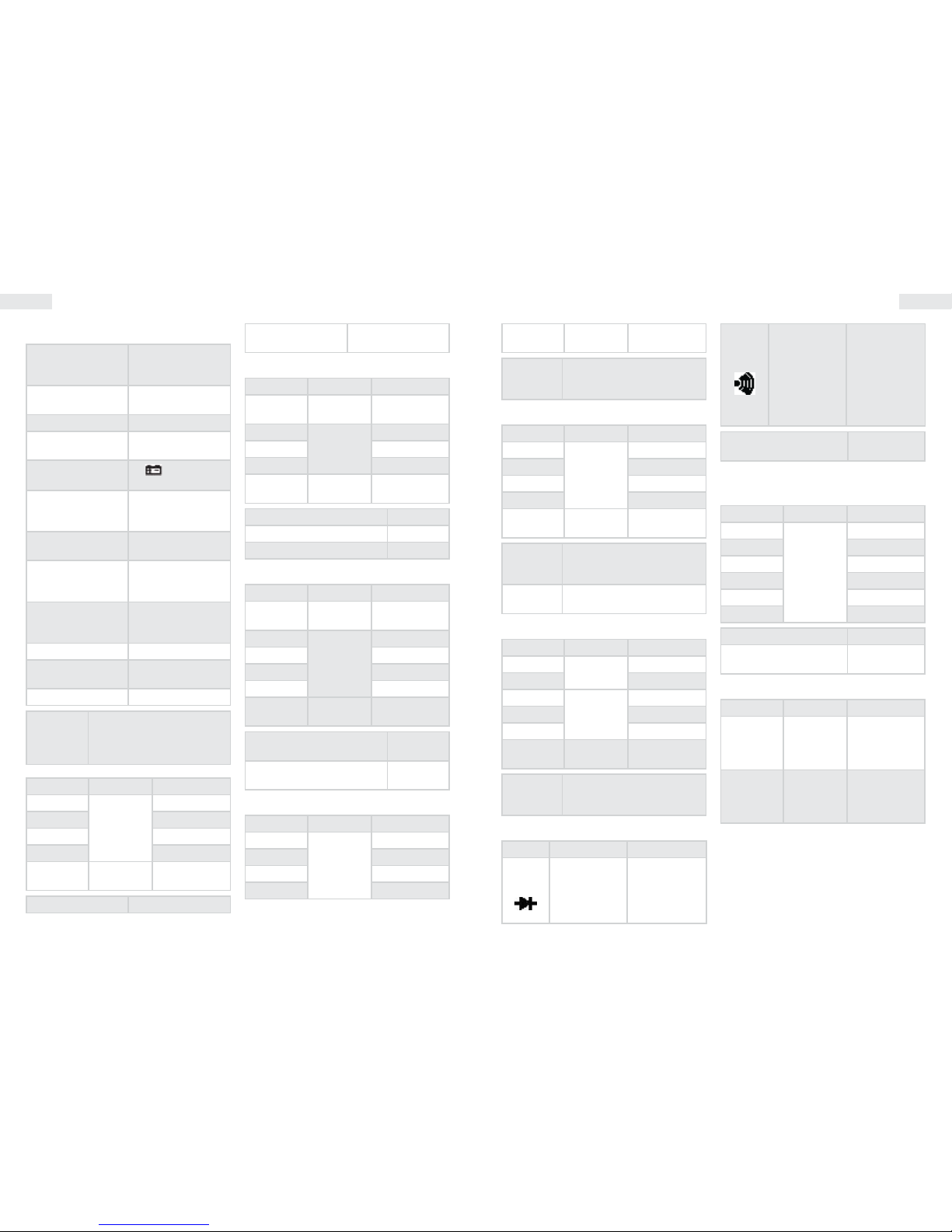
General description
Display
4 digit liquid crystal
display
Polarity
Automatic negative
polarity display
Nullication automatic
Overload display only „OL” is displayed
Low battery power
the (
) symbol
appears on the
screen
Safety prescriptions
CE EMC/LVD. Device
complies to IEC1010
standard
Protection category II, double insulation
Operating
environment
temperature: 0…40
°C, relative humidity:
< 80%
Storage
environment
temperature: -10…50
°C, relative humidity:
< 80%
Battery 9 V battery
Dimensions
190 mm x 88,5 mm x
27,5 mm
Weight
appr. 420g (with
batteries)
Electrical
characteristics
Accuracy +/- (% of
displayed value + number
of digits) at 23 +/-5 °C, <
75% relative humidity
DC voltage
Range Accuracy Resolution
400 mV
+/- (0,5%
+ 4)
0,1 mV
4 V 1 mV
40 V 10 mV
400 V 100 mV
1000 V
+/- (1,0%
+ 4)
1 V
Impedance 10 MΩ
Overload protection 1000 VDC
AC voltage
Range Accuracy Resolution
400 mV
+/- (1,5%
+ 6)
100 μV
4 V
+/- (0,8%
+ 6)
1 mV
40 V 10 mV
400 V 100 mV
750 V
+/- (1,0%
+ 6)
1 V
Impedance 10 MΩ
Overload protection 750 V AC
Measuring frequency range 40Hz-1 KHz
Resistance
Range Accuracy Resolution
400 Ω
+/- (0,8%
+ 5)
0,1 Ω
4 kΩ
+/- (0,8%
+ 4)
1 Ω
40 kΩ 10 Ω
400 kΩ 100 Ω
4 MΩ 1 kΩ
40 MΩ
+/- (1,2%
+ 5)
10 kΩ
No load output voltage 400 mV
Overload protection
250V DC/AC
RMS
DC current
Range Accuracy Resolution
400 μA
+/- (1,0%
+ 5)
0,1 μA
4 mA 1 μA
40 mA 10 μA
400 mA 100 μA
10 A
+/- (1,2% +
10)
10 mA
Overload
protection
0,5 A / 250 V „F” mark fuse, 10 A
/ 250 V fuse
AC current
Range Accuracy Resolution
400 μA
+/- (1,5%
+ 5)
0,1 μA
4 mA 1 μA
40 mA 10 μA
400 mA 100 μA
10 A
+/- (2,0% +
15)
10 mA
Overload
protection
0,5 A / 250 V „F” mark fuse, 10 A
/ 250 V fuse
Frequency
range
40Hz-1 KHz
Capacity
Range Accuracy Resolution
4 nF
+/- (2,5%
+ 6)
1 pF
40 nF 10 pF
400 nF
+/- (3,5%
+ 8)
100 pF
4 μF 1 nF
40 μF 10 nF
200 μF +/- (5,0% +
8d)
100 nF
Overload
protection
250V AC/DC RMS
Diode test
Function Description Test state
Measures
the opening
voltage of the
diode
Opening DC
current appr. 0,5
mA
Closing DC
voltage appr.
1,5 V
If the resistance
between the V/
Ohm and the
COM is lower
than 50 Ω the
device beeps
Opening
voltage appr.
0,5 V
Overload protection
250 V DC / AC
RMS
Warning: Do not connect an outside power source to the
wires!
Frequency
Range Accuracy Resolution
100 Hz
+/- (0,5%
+ 4)
0,01 Hz
1000 Hz 0,1 Hz
10 kHz 1 Hz
100 kHz 10 Hz
1 MHz 100 Hz
30 MHz 1 kHz
Inward sensitivity 0,7 V
Overload protection
250 V DC / AC
RMS
Temperature
Range Accuracy Test state
(-20-1000)°C
<400°C
±(1.0%+5)
≥400°F
±(1.5%+15)
1°C
(-4-1832)°F
<752°C
±(1.0%+5)
≥752°F
±(1.5%+15
1°F
With a K type temperature measurement
sensor
Temperature measurement
• Set the function switch to the „C” position.
• Connect the probe's connector to the „K
TEMP” connector (note the polarity) and the
other end onto the measured surface. The
temperature is displayed on the screen in °C
units.
The device operates with a special temperature
measurement probe. If the probe is not connected to
the connector, the device shows the temperature of its
environment.
Do not connect external voltage to the connectors if the
device is in temperature measurement mode.
Transistor hFE test
Function Description Test state
h
FE
Measures the
amplication
factor of the
transistor(0-1000)
(All types)
Base current
appr. 10 μA
VCE appr. 3 V
Page 3

EN
User Manual User Manual
EN
1. LCD: display the measuring value and unit.
2. Function key
2-1. Power and backlight switch: turn on/o the
power and backlight.
2-2. PK HOLD key: press it, the max. of presently
measured value is held on LCD and PH symbol
displays. Press it again, PH symbol disappears,
and the meter is exited the holding mode.
2-3. Transistor test jack.
2-4. DC/AC key set DC or AC working mode.
3. Range knob: to select measuring function
and range.
4. Voltage, resistance and frequency port
5. Common measuring port (COM)
6. Port for measuring current less than 200mA
7. Port for measuring current 20A
UsaGe
• The signs near the connectors warn if the
inward voltage or current values are above the
set values. These help to avoid damage to the
inner circuits.
• Set the proper function with the function
selection switch before measuring.
• If you do not know the measured value range,
set the switch to the highest available setting
and go backwards until you reach the proper
setting.
DC and AC voltage measurement
• Connect the black wire to the „COM” connector
and the red one to the „VΩHz” connector.
• By default the automatic range switch is
active, which is indicated by the AUTO sign on
the display. You can set the following ranges
manually by pressing the RANGE button: 400
mV/4 V/40 V/400 V/1000 V.
• Set the function selection switch to the proper
V setting and connect the wires parallelly for
the measurement.
DC and AC current measurement
• Connect the black wire to the „COM”, and the
red one to the „mA” or „10A” connectors for 400
mA or 10A measurement.
• Set the proper range with the function switch.
• Connect the connectors to the power source
parallelly.
• To measure current between 400 mA and 10 A
follow the instructions above, but connect the
red wire to the „10A” connector.
Resistance measurement
• Connect the black wire to the „COM” and the
red one to the „V/ΩHz” connector.
• Set the function switch to the desired
resistance range.
• Connect the wires parallelly.
• Press the "RANGE" button for selecting the
automatic/manual range.
Warning: Make sure the measured circuit is not under
power!
Capacity measurement
• Set the function selection switch to the -ll-
setting.
• Press the „REL” button to clear the display.
• Connect the black wire to the „COM” and the
red one to the „V/Ω” connector. Touch the
wires to the connectors of the capacitor. Pay
attention to the polarity.
Note:
Capacity measurement has automatic range selection.
Unit: 1 nF=10-3 μF or 1000 pF.
Do not connect an external voltage source or a
charged capacitor (especially high capacity ones)
to the connectors. Discharge the capacitors before
measurement. Electrolyte capacitors should be
discharged multiple times.
Diode and continuity test
• Connect the black wire to the „COM” connector
and the red one to the „VΩHz” connector.
(Note: the polarity of the red wire is +)
• Set the function switch to the position.
• Touch the wires to the connectors of the
diode. The display shows the opening voltage
of the diode.
• Connect the wires to the two points of the
circuit. If the resistance is below 50 Ω, the
device will beep.
Transistor hFE test
• Set the function switch to the hFE position.
• Determine whether the transistor is NPN or
PNP and place it into the proper connector
(this connector is included and connects to the
mA + COM connectors).
• The transistor's amplication factor is
displayed on the screen.
I = 15 μA, V = 1,5 VBC
Frequency measurement
• Connect the measuring wire or shielded cable
to the „COM” and „VΩHz” connectors.
• Set the function switch to „30MHz” and touch
the wires to the signal source.
Note:
• Do not measure frequency on higher voltage than
250V(RMS)
• In a noisy environment it is recommended to use a
shielded wire when measuring weak signals.
• Avoid touching the circuit when measuring high
voltage.
• Range selection is always automatic when measuring
frequency.
Duty cycle measurement
Set the function selection switch to 30MHz and
press the Hz/DUTY button once to measure
duty cycle.
Data hold function
By pressing the HOLD button the actual
measured value gets held on the screen until
the button is pressed again.
Warning
• When measuring voltage make sure that the wires do
not connect to the current measurement connector
and the function switch is not in a resistance or diode
measurement position. Always make sure that the wires
are connected to the proper connector.
• Take care when measuring voltage above 50V, especially
with high power devices.
• Avoid connecting to 'live' circuits.
• When measuring current make sure the circuit is not
under voltage before connecting the multimeter.
• Before measuring resistance and diode make sure the
power is disconnected for the time of measuring.
• Always use the proper function and measuring range.
If you are unsure about the range, select the highest
available and move backwards from that.
• Make sure that the measuring wires and their insulation
are intact.
• Be careful, do not go over the specied overload
thresholds.
• Only replace fuses to those of the same type and value.
• When opening the lid of the device for replacing fuses or
batteries make sure that all external power sources are
disconnected and the function switch is in OFF state.
HandlinG and
Maintenance
Handling
• Keep the multimeter dry at all times. If it
becomes wet, wipe it immediately. Liquid may
corrode the circuits.
• The multimeter may be stored and
operated only at normal temperatures. High
temperatures reduce the lifetime of electric
devices, damages the batteries and distorts/
melts the plastic parts.
• Handle the multimeter with care. Dropping
it may result in damage to the circuits and
the surface which may cause improper
functioning.
• Protect the multimeter from dust and other
dirt which may cause the untimely wearing of
the parts.
• Clean the multimeter with a wet cloth. Do not
use chemicals, solvents or strong detergents
for cleaning.
Maintenance
• Battery replacement (9 V)
• Disconnect all external circuits from the
device. Turn it o and remove all measuring
wires.
• Unscrew the bottom lid.
• Remove the depleted battery and replace to
one of the same type.
Fuse replacement
• Disconnect all external circuits from the
device. Turn it o and remove all measuring
wires.
• Unscrew the bottom lid.
• Remove the melted fuse and replace to one of
the same type and value.
Page 4
HU
Használati utasítás Használati utasítás
HU
általános leírás
Kijelző
4 digites
folyadékkristályos
kijelző
Polaritás
automatikus negatív
polaritás kijelzés
Nullázás automatikus
Túlterhelés kijelzés
csak az „OL” felirat
látható
Alacsony
telepfeszültség
az(
)szimbólum
megjelenik a kijelzőn
Biztonsági előírás
CE EMC/LVD. A
műszer megfelel az
IEC1010 szabványnak
Érintésvédelmi
osztály
II, Kettős szigetelésű
Üzemi környezet
hőmérséklet:
0…40 °C, relatív
páratartalom: < 80%
Tárolási környezet
hőmérséklet:
-10…50 °C, relatív
páratartalom: < 80%
Elem 9V jelzésű elem
Méretek
190 mm x 88,5 mm x
27,5 mm
Tömeg kb. 420g (elemekkel)
Elektromos
jellemzők
A pontosság +/- (kijelzett érték
%-a + digitek száma) 23 +/-5
°C-on, 75%-nál kisebb relatív
páratartalom esetén
DC feszültség
Méréshatár Pontosság Felbontás
400 mV
+/- (0,5%
+ 4)
0,1 mV
4 V 1 mV
40 V 10 mV
400 V 100 mV
1000 V
+/- (1,0%
+ 4)
1 V
Impedancia 10 MΩ
Túlterhelés elleni
védelem
1000 VDC
AC feszültség
Méréshatár Pontosság Felbontás
400 mV
+/- (1,5%
+ 6)
100 μV
4 V
+/- (0,8%
+ 6)
1 mV
40 V 10 mV
400 V 100 mV
750 V
+/- (1,0%
+ 6)
1 V
Impedancia 10 MΩ
Túlterhelés elleni védelem 750 V AC
Mérési frekvencia tartomány 40Hz-1 KHz
Ellenállás
Méréshatár Pontosság Felbontás
400 Ω
+/- (0,8%
+ 5)
0,1 Ω
4 kΩ
+/- (0,8%
+ 4)
1 Ω
40 kΩ 10 Ω
400 kΩ 100 Ω
4 MΩ 1 kΩ
40 MΩ
+/- (1,2%
+ 5)
10 kΩ
Terheletlen kimenő
feszültség
400 mV
Túlterhelés elleni védelem
250V DC/AC
RMS
DC áram
Méréshatár Pontosság Felbontás
400 μA
+/- (1,0%
+ 5)
0,1 μA
4 mA 1 μA
40 mA 10 μA
400 mA 100 μA
10 A
+/- (1,2% +
10)
10 mA
Túlterhelés
elleni
védelem
0,5 A / 250 V „F” jelzésű
biztosíték, 10 A / 250 V
biztosíték
AC áram
Méréshatár Pontosság Felbontás
400 μA
+/- (1,5%
+ 5)
0,1 μA
4 mA 1 μA
40 mA 10 μA
400 mA 100 μA
10 A
+/- (2,0% +
15)
10 mA
Túlterhelés
elleni
védelem
0,5 A / 250 V „F” jelzésű
biztosíték, 10 A / 250 V
biztosíték
Frekvencia
tartomány
40Hz-1 KHz
Kapacitás
Méréshatár Pontosság Felbontás
4 nF
+/- (2,5%
+ 6)
1 pF
40 nF 10 pF
400 nF
+/- (3,5%
+ 8)
100 pF
4 μF 1 nF
40 μF 10 nF
200 μF +/- (5,0% +
8d)
100 nF
Túlterhelés
elleni
védelem
250V AC/DC RMS
Dióda teszt
Funkció Leírás Teszt állapot
A dióda
nyitófeszült-
ségét méri
Nyitóirányú DC
áram kb. 0,5 mA
Záró irányú DC
feszültség kb.
1,5 V
Sípoló hang
jelzi, ha a V/
Ohm és a COM
csatlakozók
közötti
ellenállás
kisebb, mint
50 Ω
Nyitófeszültség
kb. 0,5 V
Túlterhelés elleni
védelem
250 V DC / AC
RMS
Figyelmeztetés: Ne csatlakoztasson a kapcsokra külső
feszültségforrást!
Frekvencia
Méréshatár Pontosság Felbontás
100 Hz
+/- (0,5%
+ 4)
0,01 Hz
1000 Hz 0,1 Hz
10 kHz 1 Hz
100 kHz 10 Hz
1 MHz 100 Hz
30 MHz 1 kHz
Bemeneti érzékenység 0,7 V
Túlterhelés elleni
védelem
250 V DC / AC
RMS
Hőmérséklet
Méréshatár Pontosság Teszt állapot
(-20-1000)°C
<400°C
±(1.0%+5)
≥400°F
±(1.5%+15)
1°C
(-4-1832)°F
<752°C
±(1.0%+5)
≥752°F
±(1.5%+15
1°F
K típusú hőmérsékletmérő szenzorral
Hőmérséklet mérés
• Állítsa a funkciókapcsolót a „C” állásba
• Helyezze a hőmérsékletmérő szonda
csatlakozóját a „K TEMP” aljzatba (ügyelve a
polarításra „-”) a másik végét pedig helyezze
a mérendő hőmérsékletű helyre. A kijelzőn a
mért hőmérséklet olvasható °C-ban.
A műszer speciális hőmérsékletmérő szondával működik.
Page 5

HU
Használati utasítás Használati utasítás
HU
• Nyomja meg a „RANGE” gombot az
automatikus/kézi méréshatár-váltás
kiválasztásához.
Figyelmeztetés: Biztosítsa a mérendő áramkör
feszültségmentességét!
Kapacitásmérés
• Állítsa a funkcióválasztó kapcsolót a -ll- állásba.
• Nyomja meg egyszer a „REL” feliratú gombot a
kijelző nullázásához.
• Csatlakoztassa a fekete mérőzsínórt a „COM”, a
pirosat a „V/Ω” aljzatba. Éríntse a tapogatókat a
kondenzátor kivezetéseihez, ügyelve a helyes
polarításra.
Megjegyzés:
A kapacitásmérés automata méréshatár-váltós.
Mértékegység: 1 nF=10-3 μF vagy 1000 pF.
Ne csatlakoztasson külső feszültséget vagy feltöltött
kondenzátort (különösen nagy kapacitásúakat) az
aljzatba. Mérés előtt a kondenzátorokat süsse ki. Az
elektrolit kondenzátorokat mérés előtt többször süsse ki!
Dióda és folytonosság teszt
• Csatlakoztassa a fekete műszerzsinórt a „COM”,
a pirosat a „VΩHz” aljzatba. (Megjegyzés: a
piros tapogató polaritása: +)
• Állítsa a funkció kapcsolót a állásba.
• Érintse a tapogatókat a dióda kivezetéseihez. A
kijelzőn a dióda nyitófeszültsége látható.
• Érintse a tapogatókat az áramkör két pontjára.
Sípoló hang jelez, ha az ellenállás kisebb 50
Ω-nál.
Tranzisztor hFE teszt
• Állítsa a funkciókapcsolót a hFE állásba
• Határozza meg, hogy a tranzisztor NPN vagy
PNP, és helyezze az alkatrészt a lábkiosztásának
megfelelő csatlakozóba (ezen csatlakozó aljzat
a műszer tartozéka és a mA + COM bemeneti
aljzatokba csatlakozik).
• A kijelzőről a tranzisztor áramerősítési
tényezője olvasható le.
I = 15 μA, V = 1,5 VBC
Frekvenciamérés
• Csatlakoztassa a műszerzsinórt vagy az
árnyékolt kábelt a „COM” és a „VΩHz”
aljzatokba.
• Állítsa a funkciókapcsolót „30MHz” állásba és
érintse a tapogatókat a jelforráshoz.
Megjegyzés:
• Ne mérjen 250 V(RMS)nál nagyobb feszültségen
frekvenciát.
• Zajos környezetben célszerű árnyékolt kábel használni
kis jelek mérésénél.
• Nagyfeszültségű méréskor kerülje az áramkör érintését.
• Frekvenciamérésnél a méréshatár-váltás mindig
automatikus.
Kitöltési tényező mérés
Állítsa a funkciókapcsolót 30MHz állásba, majd
egyszer nyomja meg a Hz/DUTY gombot, a
kitöltési tényező méréséhez.
Adatrögzítés
A ’HOLD’ gomb megnyomásának hatására a
kijelzőn az éppen akkor mért érték marad, addig
amíg újra meg
nem nyomja ezt a gombot.
Figyelmeztetés
• Feszültségmérésnél biztosítsa, hogy a vezetékek
ne csatlakozzanak árammérő aljzathoz és a
funkciókapcsoló ne legyen ellenállás vagy dióda
ellenőrző állásban.Mindig ellenőrizze, hogy a mérendő
mennyiségnek megfelelő aljzatba csatlakoztatta-e a
vezetéket.
• Legyen körültekintő 50 V-nál nagyobb feszültség
mérésekor, különösen erősáramú berendezéseknél.
• Kerülje az „élő” áramkörökhöz való csatlakozást.
• Árammérésnél az áramkört feszültségmentesítse,
mielőtt csatlakoztatná hozzá a multimétert.
• Ellenállásmérés és dióda tesztelés előtt gondoskodjon
az áramkör feszültségmentesítéséről a mérés idejére.
• Mindig a mérésnek megfelelő funkciót és méréshatárt
válassza. Ha kétséges a mérendő mennyiség
nagyságrendje, válassza a legmagasabb méréshatárt és
onnan haladjon visszafelé.
• Győződjön meg a műszerzsinór hibátlan állapotáról, a
szigetelés sértetlenségéről.
• Legyen óvatos, ne lépje túl a leírásban megadott
túlterheléshatárokat.
• Biztosítékot csak azonos típusúra és értékűre cseréljen.
• Biztosíték- vagy elemcserénél a műszer tokjának
kinyitása előtt kapcsoljon le minden külső áramkört és
állítsa a funkciókapcsolót OFF állásba.
Ha a szondát nem csatlakoztatjuk az aljzatba, akkor a
műszer a környezete hőmérsékletét mutatja.
Ne kapcsoljon a bemenetekre külső feszültséget, ha a
műszer hőmérsékletmérő állásban van.
Tranzisztor hFE teszt
Funkció Leírás Teszt állapot
h
FE
A tranzisztor
áramerősítési
tényezőjét méri
(0-1000)
(Minden típus)
Bázisáram kb.
10 μA
VCE kb. 3 V
1.LCD: kijelzi a mért értéket és a mértékegységet
2.Funkció gombok:
2-1. “select” key : select DC/AC ,frequency and
Duty cycle . Hz/DUTY Key: when measure
DCA,press the key to switch ACA.When measure
frequency ,press the key to switch frequency/
duty cycle(1~99%).
2-2. RANGE Key: select working mode
of automatic measurement and manual
measurement.the default mode is automatic
measurement and “AUTO” is displayed ,press
the key turn into manual measurement ,press
the key for 2 sec. will return to automatic
measurement condition.
2-3. press the key at voltage ,current and
capacitance range, reading is reset and enter
into relative value measurement ,LCD displaying
“REL” symbol,press it again will exit the function.
2-4.HOLD Key:Press the key ,the present value is
held on LCD and display “HOLD” ,press it again
will exit the function ; Press the key for 2 sec. will
turn to the backlight.
3.Rotary Switch: selecting measuring function
and range.
4.Voltage, Resistance, Frequency socket.
5.GND.
6.COM for measuring current less than 400mA.
7.COM for measuring current 10A.
Használat
• Az aljzatok melletti jelzések gyelmeztetnek,
hogy a bemenő feszültség vagy áram ne
haladja meg a jelzett értéket. Így elkerülheti a
belső áramkörök sérülését.
• A funkcióválasztó kapcsolót a mérés előtt
állítsa a megfelelő állásba (funkcióhoz)
• Ha a mérendő mennyiség nagyságrendjét
nem ismeri, állítsa a kapcsolót a legmagasabb
méréshatárra és onnan haladjon visszafelé,
amíg a megfelelő értéket eléri.
DC és AC feszültség mérése
• Csatlakoztassa a fekete csatlakozót a „COM”, a
piros csatlakozót a „VΩHz” aljzatba.
• Alapállapotban az automata méréshatár-váltás
aktív, amit a kijelzőn az „AUTO”felirat jelez. A
RANGE gomb megnyomásával kézzel állíthatja
a méréshatárt: 400 mV/4 V/40 V/400 V/1000 V.
• Állítsa a funkcióválasztó kapcsolót a megfelelő
V pozícióba és csatlakoztassa a tapogatókat
párhuzamosan a feszültségforrással a mérés
idejére.
DC és AC áram mérése
• Csatlakoztassa a fekete vezetéket a „COM”, a
piros vezetéket pedig a „mA” vagy „10A” jelzésű
aljzatba, 400 mA-es illetve 10A-es méréshez.
• Állítsa a funkció kapcsolót a megfelelő
méréshatárhoz.
• Csatlakoztassa a tapogatókat sorosan az
áramforrással a méréshez.
• 400 mA és 10 A közötti áram méréséhez az
előző pontokat kövesse, de a piros mérőzsinórt
a „10A” jelzésű aljzatba csatlakoztassa.
Ellenállásmérés
• Csatlakoztassa a fekete vezetéket a „COM”, a
piros vezetéket pedig a „V/ΩHz” aljzatba.
• Állítsa a funkció kapcsolót a kívánt ellenállás
méréshatárra.
• Csatlakoztassa az érintkezőket a mérendő
áramkörrel párhuzamosan.
Page 6

Manual de utilizare
ROHU
Használati utasítás
descriere Generală
Aşaj
Aşaj cu 4 cifre cu
cristale lichide
Polaritate
Indicare automată de
polaritate negativă
Anulare automatic
Indicator
suprasarcină
Nu se vede decât „OL”
Baterie descărcată
simbolul (
)apare
pe aşaj
Standarde de
siguranţă
CE EMC/LVD.
Instrumentul
îndeplineşte
standardul IEC1010
Clasa de protecţie
de atingere
II, Izolat dublu
Mediu de lucru
temperatură: 0…40
°C, umiditate relativă:
< 80%
Mediu de
depozitare
temperatură: -10…50
°C, umiditate relativă:
< 80%
Baterie 1 buc 9 V
Mărimi
190 mm x 88,5 mm x
27,5 mm
Greutate cca. 420g (cu baterii)
Caracteristici
electrice
Acurateţea +/- (% valoare
aşată + nr. cifrelor) la 23 +/-5
°C, în caz de umiditate relativă
< 75%
Tensiune DC
Domeniu Acurateţe Rezoluţie
400 mV
+/- (0,5%
+ 4)
0,1 mV
4 V 1 mV
40 V 10 mV
400 V 100 mV
1000 V
+/- (1,0%
+ 4)
1 V
Impedanţă 10 MΩ
Protecţie la
suprasarcină
1000 VDC
Tensiune AC
Domeniu Acurateţe Rezoluţie
400 mV
+/- (1,5%
+ 6)
100 μV
4 V
+/- (0,8%
+ 6)
1 mV
40 V 10 mV
400 V 100 mV
750 V
+/- (1,0%
+ 6)
1 V
Impedanţă 10 MΩ
Protecţie la suprasarcină 750 V AC
Domeniu de frecvenţă de
măsurat
40Hz-1 KHz
Rezistenţă
Domeniu Acurateţe Rezoluţie
400 Ω
+/- (0,8%
+ 5)
0,1 Ω
4 kΩ
+/- (0,8%
+ 4)
1 Ω
40 kΩ 10 Ω
400 kΩ 100 Ω
4 MΩ 1 kΩ
40 MΩ
+/- (1,2%
+ 5)
10 kΩ
Tensiune de ieşire fără
sarcină
400 mV
Protecţie la suprasarcină
250V DC/AC
RMS
Curent DC
Domeniu Acurateţe Rezoluţie
400 μA
+/- (1,0%
+ 5)
0,1 μA
4 mA 1 μA
40 mA 10 μA
400 mA 100 μA
kezelés és karbantartás
Kezelés
• Tartsa a multimétert szárazon. Ha nedvesség
éri, törölje le azonnal. A folyadékok korrodálják
az áramköröket.
• A multimétert tárolni és használni csak normál
hőmérsékleten szabad. A magas hőmérséklet
rövidíti az elektronikus eszközök élettartamát,
megrongálja az elemeket, és eltorzítja,
megolvasztja a műanyag alkatrészeket.
• Bánjon óvatosan és gondosan a multiméterrel.
Az elejtés kárt tesz az áramkörökben és a
tokban, ami a multiméter helytelen működését
okozza.
• Óvja a multimétert a portól és egyéb
szennyeződésektől, amik az alkatrészek idő
előtti kopását eredményezik.
• A multimétert nedves ruhával tisztíthatja. Ne
alkalmazzon vegyszereket, oldószereket vagy
erős tisztítószereket a tisztításhoz.
Karbantartás
• Elemcsere (9V)
• Kapcsoljon le minden külső áramkört a
műszerről. Kapcsolja ki a multimétert és a
műszerzsinórt húzza ki az aljzatból.
• Csavarja ki a csavarokat és emelje le az alsó
fedelet.
• Távolítsa el a lemerült elemet és cserélje ki
ugyanolyan típusúra.
Biztosítékcsere
• Kapcsoljon le minden külső áramkört a
műszerről. Állítsa a funkciókapcsolót OFF
állásba és a műszerzsinórt húzza ki az aljzatból.
• Csavarja ki a csavarokat és emelje le az alsó
fedelet.
• Cserélje ki a kiolvadt biztosítékot ugyanolyan
típusúra és értékűre.
Page 7

RO
Manual de utilizare Manual de utilizare
RO
10 A
+/- (1,2% +
10)
10 mA
Protecţie la
suprasarcină
Fuzibil 0,5 A / 250 V marcat cu
„F”(rapid), fuzibil 10 A / 250 V
Curent AC
Domeniu Acurateţe Rezoluţie
400 μA
+/- (1,5%
+ 5)
0,1 μA
4 mA 1 μA
40 mA 10 μA
400 mA 100 μA
10 A
+/- (2,0% +
15)
10 mA
Protecţie la
suprasarcină
Fuzibil 0,5 A / 250 V marcat cu
„F”(rapid), fuzibil 10 A / 250 V
Domeniu de
frecvenţă
40Hz-1 KHz
Capacitate
Domeniu Acurateţe Rezoluţie
4 nF
+/- (2,5%
+ 6)
1 pF
40 nF 10 pF
400 nF
+/- (3,5%
+ 8)
100 pF
4 μF 1 nF
40 μF 10 nF
200 μF +/- (5,0% +
8d)
100 nF
Protecţie la
suprasarcină
250V AC/DC RMS
Test diode
Funcţia Descriere Stare test
Măsoară
tensiunea de
deschidere al
diodei
Curent DC în
direcţia de
deschidere cca.
0,5 mA
Tensiune DC
în direcţia de
închidere cca.
1,5 V
Semnal sonor
indică dacă
între contactele
V/Ohm şi COM
rezistenţa
măsurată este
mai mică de
50 Ω
Tensiunea de
deschidere cca.
0,5 V
Protecţie la suprasarcină
250 V DC / AC
RMS
Atenţie: Nu conectaţi pe contactele instrumentului sursă
exterioară de tensiune!
Frecvenţă
Domeniu Acurateţe Rezoluţie
100 Hz
+/- (0,5%
+ 4)
0,01 Hz
1000 Hz 0,1 Hz
10 kHz 1 Hz
100 kHz 10 Hz
1 MHz 100 Hz
30 MHz 1 kHz
Sensibilitate de intrare 0,7 V
Protecţie la suprasarcină
250 V DC / AC
RMS
Temperatură
Domeniu Acurateţe Stare test
(-20-1000)°C
<400°C
±(1.0%+5)
≥400°F
±(1.5%+15)
1°C
(-4-1832)°F
<752°C
±(1.0%+5)
≥752°F
±(1.5%+15
1°F
Cu senzor de termometru tip K
Măsurare temperatur
• Setaţi comutatorul de funcţii la poziţia „C”
• Aşezaţi contactele sondei de termometru în
mufele „K TEMP” (având grijă la polaritate „-”)
iar capătul celălalt aşezaţi la locul ce doriţi să
măsuraţi. Pe aşaj se poate citi temperatura
măsurată în °C.
Instrumentul funcţionează cu sondă termometru specială.
Dacă sonda nu conectaţi la mufe atunci instrumentul
indică temperatura ambientală.
Nu conectaţi la intrări tensiune exterioară dacă
instrumentul este setat la măsurare temperatură.
Test hFE tranzistor
Funcţia Descriere Stare test
h
FE
Măsoară factorul
de amplicare
în curent al
tranzistorului
(0-1000)
(Orice tip)
Curent de
bază cca. 10
μA
VCE cca. 3 V
1. LCD: Aşează valoarea măsurată şi unitatea de
măsură
2. Buton Funcţii
2-1. Buton Select: selectează între CC/CA,
frecvenţă şi factor de umplere.
2-2 Buton Domeniu. Selectează între modul de
măsurare automat şi manual. Modul implicit
este cel Automat care este aşat şi pe aşaj.
Apăsând butonul, aparatul trece la modul
manual. Apăsând 2 sec. aparatul revine la
modul automat.
2-3. Apăsând, valoarea de tensiune, curent şi
capacitate va resetată şi aparatul intră în
regim de măsurare relativă, ce va aşat pe
aşaj (REL). Apăsând încă o dată, aparatul
revine la modul normal.
2-4. Apăsând valoarea instantanee va xată
pe aşaj împreună cu mesajul HOLD. Apăsând
scurt, aparatul revine la normal. Apăsând timp
de 2 sec. va activa iluminarea de fundal.
3. Comutator rotativ – selectează funcţia şi
domeniul de măsurare.
4. Mufă intrare Tensiune, Rezistenţă, Frecvenţă
5. GND Masă comună
6. COM pt. măsurarea curenţilor sub 400 mA.
7. COM pt. măsurarea curenţilor până la 10A
Utilizare
• Semnele de lângă prize ne avertizează că
tensiunea sau curentul de intrare să nu
depăşească valoarea indicată. Aşa puteţi evita
deteriorarea circuitelor interne.
• Selectorul de funcţii comutaţi la poziţia
(funcţia) corespunzătoare înainte de măsurare.
• Dacă nu ştiţi că valoarea ce va măsurată
în ce domeniu se încadrează selectaţi
domeniul cel mai mare şi apoi de acolo să
treceţi înapoi, până când ajungeţi la valoarea
corespunzătoare.
Măsurare tensiune DC şi AC
• Conectaţi conectorul negru la "COM",
conectorul roşu la „VΩHz”.
• În mod implicit, comutarea de domenii
automat este activ, ceeace este indicat pe
aşaj cu textul "Auto". Cu apăsarea butonului
RANGE puteţi regla manual domeniile: 400
mV/4 V/40 V/400 V/1000 V.
• Setaţi comutatorul de funcţii în poziţia V
corectă şi conectaţi în paralel tentaculele cu
sursa de tensiune pe perioada de măsurare.
Măsurare curent DC şi AC
• Conectaţi cablul de măsură neagră la „COM” iar
cel roşu la „mA” sau „10A” pentru măsurători de
400 mA respectiv 10A.
• Aşezaţi comutatorul de funcţii la domeniul de
măsurat potrivit.
• Conectaţi tentaculele în serie cu circuitul ce va
măsurat.
• Pentru măsurarea curentului cu intensitate
între 400 mA şi10 A urmaţi paşii anteriori dar
cablul de măsurat roşie conectaţi la borna
„10A”.
Măsurare rezistenţă
• Conectaţi cablul de măsurat negru la „COM” iar
cel roşu la „V/ΩHz”.
Page 8

RO
Manual de utilizare Manual de utilizare
RO
• Aşezaţi comutatorul de funcţii la domeniul
dorit de măsurare rezistenţe.
• Conectaţi tentaculele în paralel cu circuitul ce
va măsurat.
• Apăsaţi butonul „RANGE” pentru alegerea
schimbării domeniului în mod automat/
manual.
Avertisment: Asiguraţi-vă că circuitul ce va testat nu este
sub tensiune!
Măsurare de capacitate
• Aşezaţi comutatorul de funcţii la poziţia -ll-.
• Apăsaţi odată butonul „REL” pentru anularea
aşajului.
• Conectaţi cablul de măsură neagră la „COM”
iar cel roşu la„V/Ω”. Atingeţi tentaculele la
terminalele condensatorului ţinând cont de
polaritatea acestuia.
Notă:
Măsurarea de capacitate este cu schimbare de domeniu de
măsurat automat.
Unitate de măsură: 1 nF=10-3 μF vagy 1000 pF.
Nu conectaţi tensiune exterioară sau condensator încărcat
(în special de mare capacitate) la bornele instrumentului.
Înainte de măsurare descărcaţi condensatoarele.
Condensatoarele electrolitice descărcaţi de mai multe ori
înainte de măsurare!
Test de diode şi continuitate
• Conectaţi cablul de măsurat neagră la „COM”
iar cel roşu la „VΩHz”. (Notă: tentaculul roşu are
polaritatea: +)
• Aşezaţi comutatorul de funcţii la poziţia
• Atingeţi tentaculele la terminalele diodei.
Pe aşaj se vede tensiunea de deschidere a
diodei.
• Atingeţi tentaculele la două puncte al
circuitului. Semnal sonor va indica dacă
rezistenţa este mai mică de 50 Ω.
Test hFE de tranzistor
• Aşezaţi comutatorul de funcţii la poziţia hFE.
• Determinaţi că tranzistorul este NPN sau PNP
şi aşezaţi componentul în soclul corespunzător
ordinii picioarelor acestuia (acest soclu face
parte din accesoriile instrumentului şi se
conectează la bornele mA + COM al acestuia).
• De pe aşaj se poate citi factorul de
amplicare în curent al tranzistorului. I = 15 μA,
V = 1,5 VBC
Măsurare de frecvenţă
• Conectaţi cablul de măsurat sau cablul coaxial
la „COM” şi la „VΩHz”.
• Aşezaţi comutatorul de funcţii la „30MHz” şi
atingeţi tentaculele la sursa de semnal.
Notă:
• Nu măsuraţi frecvenţă la tensiune mai mare de 250
V(RMS).
• În mediu zgomotos este indicat folosirea cablului
ecranat la măsurarea semnalelor slabe.
• La măsurarea sub înaltă tensiune evitaţi atingerea
circuitului.
• La măsurarea frecvenţei schimbarea domeniului de
măsurat este întotdeauna automatică.
Măsurare factor de umplere
Aşezaţi comutatorul de funcţii la poziţia 30MHz
apoi apăsaţi odată butonul Hz/DUTY pentru
măsurarea factorului de umplere.
Menţinere date
La apăsarea butonului ’HOLD’ pe aşaj se va
menţine valoarea tocmai măsurată până apăsaţi
butonul din nou.
Atenţie
• La măsurare de tensiune asiguraţi ca rele să nu
e conectaţi la borne de măsurare intensitate, nici
comutatorul de funcţii să nu e în poziţia de rezistenţă
sau diode. Totdeauna vericaţi să e cablurile de
măsurat conectate la bornele corespunzătoare
domeniului de măsurat.
• Fiţi prudent la măsurarea tensiunii peste 50 V în special
în dispozitive cu curent de mare putere.
• Evitaţi conectarea la circuitele "vii".
• La măsurare curent scoateţi circuitul de sub tensiune
înainte de a vă conecta cu multimetru.
• Înainte de măsurare rezistenţă şi testare diodă
asiguraţi scoaterea circuitului de sub tensiune în timpul
măsurării.
• Întotdeauna utilizaţi funcţia şi domeniul de măsurare
corespunzătoare măsurării. Dacă aveţi dubii în legătură
cu domeniul de măsurare alegeţi cea mai mare şi apoi
treceţi înapoi la treaptă mai mică dacă este cazul.
• Asiguraţi-vă că cablul de măsurat este în stare perfectă,
izolaţia este nevătămată.
• Fiţi precaut şi nu depăşiţi limitele de suprasarcină
stabilite în descriere.
• Fuzibil schimbaţi doar cu acelaşi tip şi de acelaşi valoare.
• La schimbare fuzibil sau baterii înainte de deschiderea
carcasei instrumentului deconectaţi toate circuitele de
pe instrument şi comutatorul de funcţii setaţi la poziţia
OFF.
Utilizare şi întreţinere
Utilizare
• Păstraţi multimetrul în stare uscată. Dacă se
umezeşte ştergeţi imediat. Lichidele corodează
circuitele.
• Depozitaţi şi utilizaţi multimetrul doar
latemperatură normală. Temperatura înaltă
scurtează durata de viaţă al componentelor
electronice, deteriorează bateriile şi
deformează, topeşte componentele plastice.
• Trataţi multimetrul prudent şi grijuliu.
Scăparea jos deteriorează circuitele şi carcasa
ceeace duce la funcţionarea inadecvată a
multimetrului.
• Protejaţi multimetrul de la praf şi de alte
impurităţi care provoacă uzura timpurie al
componentelor acestuia.
• Puteţi curăţa multimetrul cu cârpă umedă. Nu
utilizaţi solvenţi, diluanţi sau detergenţi tari la
curăţare.
Întreţinere
• Schimbarea bateriei (1 buc 9V)
• Deconectaţi toate circuitele exterioare de
pe instrument. Opriţi multimetrul şi scoateţi
cablurile de măsură din borne.
• Deşurubaţi şuruburile şi scoateţi capacul din
spate.
• Înlăturaţi bateriile uzate şi schimbaţi-le cu
acelaşi tip.
Schimbarea fuzibilului
• Deconectaţi toate circuitele exterioare de pe
instrument. Setaţi comutatorul de funcţii la
poziţia OFF şi scoateţi cablurile de măsură din
borne.
• Deşurubaţi şuruburile şi scoateţi capacul din
spate.
• Schimbaţi fuzibilul topit cu alta de acelaşi tip
şi valoare.
Page 9

SK
Uživateľská príručka Uživateľská príručka
SK
10 A
+/- (1,2% +
10)
10 mA
Ochrana
proti
pretaženiu
0,5 A / 250 V s „F” označením,
poiskta 10 A / 250 V poistka
AC prúd
Meraci limit Presnosť Rozlíšenie
400 μA
+/- (1,5%
+ 5)
0,1 μA
4 mA 1 μA
40 mA 10 μA
400 mA 100 μA
10 A
+/- (2,0% +
15)
10 mA
Ochrana
proti
pretaženiu
0,5 A / 250 V s „F” označením,
poiskta 10 A / 250 V poistka
Rozsah
frekvencie
40Hz-1 KHz
Kapacita
Meraci limit Presnosť Rozlíšenie
4 nF
+/- (2,5%
+ 6)
1 pF
40 nF 10 pF
400 nF
+/- (3,5%
+ 8)
100 pF
4 μF 1 nF
40 μF 10 nF
200 μF +/- (5,0% +
8d)
100 nF
Ochrana
proti
pretaženiu
250V AC/DC RMS
Test diody
Funkcia Opis Stav testovanie
Merie vstupne
napätie diody
Vstupný prúd
DC o. 0,5 mA
Výstupné
napeäie DC o.
1,5 V
Pípovanie
signalizuje, ked
napätie medzi
konektormi V/
Ohm a COM je
menej, ako 50 Ω
Vstuné napätie
o 0,5 V
Ochrana proti pretaženiu
250 V DC / AC
RMS
Upozornenie: Nepripájajte externé napätie na spojky!
Frekvencia
Meraci limit Presnosť Rozlíšenie
100 Hz
+/- (0,5%
+ 4)
0,01 Hz
1000 Hz 0,1 Hz
10 kHz 1 Hz
100 kHz 10 Hz
1 MHz 100 Hz
30 MHz 1 kHz
Vstupná citlivosť 0,7 V
Ochrana proti pretaženiu
250 V DC / AC
RMS
Teplota
Meraci limit Presnosť Rozlíšenie
(-20-1000)°C
<400°C
±(1.0%+5)
≥400°F
±(1.5%+15)
1°C
(-4-1832)°F
<752°C
±(1.0%+5)
≥752°F
±(1.5%+15
1°F
So senzorom meranie teplotu typu K
Meranie teploty
• Nastavte si tlačidla funkcii do pozicie „C”
• Vložte konektora sondy meranie teploty do
zásuvky „K TEMP” (zabezpečovanim spravnej
polarity „-”) a druhú koncovku na teplotu
meraného miesta. Na displeji sa objavi
nameraná teplota °C
Pijimač funguje s špecialnou sondou meranie teplotu
Ked sondu nepripojime do zásuvky, prijimač ukazuje
teplotu jeho prostredia
všeobecné opisy
Displej
4 digitovy displej s
tekutným kristalom
Polarita
displej automatickej
negativnej polarity
Nulovanie automaticky
Displej preťažovanie
viditelny je len „OL”
napis
Nizke napätie
baterie
(
)() simbólum sa
objavi na displej
Bezpečnostné
predpisy
CE EMC/LVD. Prijimač
je vhdný pre štandard
IEC1010
Kategoria ochrany II, Dvojitá izolacia
Priemyselné
prostredie
teplota: 0…40 °C,
relatívna vlhkosť
páry: < 80%
úložiske prostredie
teplota: -10…50 °C,
relatívna vlhkosť
páry: < 80%
Bateria 1 ks baterie 9V typu
Rozmery
190 mm x 88,5 mm x
27,5 mm
Váha kb. 420g (s bateriou)
Elektronické
funkcie
Presnosť +/- (Hodnota %-a
+ cislo digitov) 23 +/-5
°C-on,menej ako 75% k
relatívnej vlhkosti páry
DC napätie
Meraci limit Presnosť Rozlíšenie
400 mV
+/- (0,5%
+ 4)
0,1 mV
4 V 1 mV
40 V 10 mV
400 V 100 mV
1000 V
+/- (1,0%
+ 4)
1 V
Impedancia 10 MΩ
Ochrana proti
pretaženiu
1000 VDC
AC napätie
Meraci limit Presnosť Rozlíšenie
400 mV
+/- (1,5%
+ 6)
100 μV
4 V
+/- (0,8%
+ 6)
1 mV
40 V 10 mV
400 V 100 mV
750 V
+/- (1,0%
+ 6)
1 V
Impedancia 10 MΩ
Ochrana proti pretaženiu 750 V AC
Rozsah meriacej frekvencii 40Hz-1 KHz
Odpor
Meraci limit Presnosť Rozlíšenie
400 Ω
+/- (0,8%
+ 5)
0,1 Ω
4 kΩ
+/- (0,8%
+ 4)
1 Ω
40 kΩ 10 Ω
400 kΩ 100 Ω
4 MΩ 1 kΩ
40 MΩ
+/- (1,2%
+ 5)
10 kΩ
Vystupne napätie
nepretažené
400 mV
Ochrana proti pretaženiu
250V DC/AC
RMS
DC prúd
Meraci limit Presnosť Rozlíšenie
400 μA
+/- (1,0%
+ 5)
0,1 μA
4 mA 1 μA
40 mA 10 μA
400 mA 100 μA
Page 10

SK
Uživateľská príručka Uživateľská príručka
SK
obvodu.
• Stlačte tlačidlo „RANGE” automaticky/manual
na vybranie kapacity.
Upozornenie: Zabezpečte, aby merani obvod prúdu bol
bez napäti!
Meranie kapacity
• Nastavte spinača fukncii do pozicie -ll- .
• Stlačte tlačidlo „REL” 1x pre nulovanie displeja.
• Prpojte čiernu meraciu šnúru do zásuvky
„COM”, a čer vený do zásuvky „VΩHz” . Dotknite
chapadlá k zásuvky kondenzatora, a uistite sa
o spravnej polarity.
Poznámka:
Meranie kapacity automatický zmení.
Jednotka: 1 = 10.3 nF mF a 1000 pF.
Nepripájajte externé napätie alebo na ťarchu kondenzátor
(najmä s veľkou kapacitou) do zásuvky. Pred meranie
kondenzátorov vybite to. Pred. meraním elektrolytické
kondenzátory vybite to niekoľkokrát!
Test diódy a kontinuity
• Pripojte čiernu šnúrú zariadenie do
zásvuky "COM", a červenú do "VΩHz" .
(Poznámka:polarita červených chápadlá: +)
• Nastavte prepínač funkcií do polohy .
• Dotyknite chapadlá výstupnej zísuvky diódy.
Na displeji sa zobrazí vstupné napätie diody.
• Dotyknite chápadlá k dve body obvode
prúdu. Pípnutie signalizuje, že odpor je nižší
ako 50 Ω.
Test tranzistora hFE
• Nastavte spínača funkcií do pozície hFE
• Uistite sa, či transistor je NPN alebo PNP,
a vložte súčiastok do vhodného konektora
(tento konektor zásuvka je príslušenstvom
zariadenia a pripojí sa do zásuvky mA +COM ).
• Na displeji je zobrazený faktor zosilavacej
prúdu tranzistora. I = 15 uA, V = 1,5 VBC
Meranie frekvencie
• Pripojte šnúru zariadenia alebo tienený kábel
do zásuvky"COM" a "VΩHz".
• Nastavte spínača funkcií do pozície "30MHz"a
dotknite chápadlá k zdroju signálu.
Poznámka:
• Nemerajte frekvenciu na vyššie napätie, ako 250 W
(RMS) .
• V hlučnom prostredí používajte tienený kábel pre
meranie malých signálov.
• Vyhnite si dotýkanie obvodu pri meranie vysokej
napätie.
• U meranie frekvencie zmenenie kapacity je vždy
automatický.
DZ meranie
Nastavte spínača funkcií do pozíciu 30MHz
pozíciu, potom stlačte tlačidlo Hz / CLA jeden
krát, na meranie cyklusa.
Uloženie dát
Pri stlačením tlačidla 'Hold' zobrazuje aktuálnú
nameranú hodnotu, kým nepotlačíte to znova.
Upozornenie
• K meranie napätie zabezpečujte, aby vodiče neboli
pripojený k zásuvke galvanometra a aby spínač funkciíí
nebol v polohe odporu alebo diódu. Vždy kontrolujte,
aby kábel bol správne pripojený do zásuvky vhodnej
meranej hmotnosťu.
• Buďte opatrní u meraní napätie, viac ako 50, najmä
energetických zariadení.
• Vyhnite si pripojenia k "živého" obvodu.
• U meranie prúdu vždy odpojte napätie z obvod pred
pripojením k multimetra.
• Pred testovanie odporu a diody vždy odpojte napätie z
obvodu pocas meranie.
• Pre meranie vždy používajte vhodné meracie funkcie
a schopnosti. Ak pochybujete o veľkosťi meraciej
hmostnosti, vyberte si najvyššiu kapacitu, a potom sa
vrátitte späť.
• Uistite sa o perfektný stav šnúry zariadenia a o
neporušenosti izolácie..
• Buďte opatrní, neprekročte limit preťaženosti.
• Vymente poistky len na rovnakého typu a hodnoty.
• Pred odstránenie krytu zariedenia u výmenu postky
alebo batérie, vypnite všetky obvody prúdu a nastavte
spínača funkcií do pozície OFF.
starostlivosť a údržba
Ošetrenie
• Multimeter uchovávajte sucho. Ak ho vlhkosť
dtýka, zotrite okamžite. Kvapaliny korrodujú
obvodov.
• Uchovávať a používať multimeter iba v
normálnom teplote! Vysoká teplota skratčuje
životnosť elektronických zariadení, poškodujú
prvky a batérie, tavenie plastových dielov.
• Zaobchádzajte so zariadením opatrne a
starostlivo. Zahodenie poškodí obvodov kryt,
čo spôsobí nesprávnu prevádzku multimetra.
• Chráňte multimeter odprachu a iných nečistôt,
ktoré spôsobujú predčasné opotrebenie
súčiastky.
Nezapinajte vonkajšie napätie na vstupy, ked zariadenie
je v pozicie meranie teploty
Tranzistor hFE test
Funkcia Opis
Stav
testovanie
h
FE
Namerá factor
zosilovanie prúdu
tranzistora
(0-1000)
(Všetké typy)
Prúd bázy o.
10 μA
VCE o 3 V
1.LCD: zobrazuje namerané hodnoty a ich
jednotky.
2. Tlačítka funkcií:
2-1. “výberový” ovládač: výber DC/AC ,
frekvencie a Vybíjacieho cyklu.
Hz/DUTY ovládač: pre meranie DC A, nastavte
ovládač do polohy AC A.
Pre meranie frekvencie, nastavte ovládač do
polohy frequency/duty cycle (1~99%).
2-2. RANGE ovládač: umožňuje výber medzi
automatickým pracovným režimom a
manuálnym pracovným režimom, v
základnom nastavení je nastavený
automatický režim, na displeji svieti “AUTO”, po
stlačení ovládaču prístroj prejde na manuálny
režim. Ak tlačidlo podržíte dlhšie ako 2 s
prístroj sa vráti do automatického režimu.
2-3. stlačte tlačidlo pri meraní napätia, prúdu
a kapacity, a prístroj sa nastavý na meranie
relatívnej hodnoty, symbol "REL" sa zobrazí na
displeji, po opätovnom stlačení sa táto funkcia
vypne.
2-4.HOLD ovládač: Po stlačení tlačidla sa
aktuálna nameraná hodnota bude stále
zobrazovať na displeji spolu s nápisom
“HOLD”, po opätovnom stlačení sa táto funkcia
vypne. Ak tlačidlo podržíte dlhšie ako 2 s
rozsvieti sa podsvietenie.
3.Otočný ovládač: slúžiaci na výber typu a
rozsahu merania.
4. Vstup pre merania prúdu, odporu a
frekvencie.
5.GND.
6.COM vstup pre merania pod 400mA.
7.COM vstup pre merania do 10A.
poUžiívanie
• Znamienky vedľa zásuvkami upozornia, aby
vstupné napätie alebo prúd neprekročilo
signalizovanú hodnotu, a nedošlo k
poškodeniu vnútorných obvodov.
• Nastavte tlacčdla funkcii do vhodnú poziciu (k
funkciu)
• Ak nepoznáte veľkosť nameranej hmotnosťu,
nastavte spinača na najvyššu kapacitu a potom
naspät, kým nedosiahnete vhodnú hodnotu
Meranie napätie DC a AC
• Prpojte si čierny konektor do zásuvky „COM”, a
červený konektor do zásuvky „VΩHz” .
• V štandardnom stave menič kapacty je aktívny,
ktorý ukazuje napis „AUTO” na displej. So
stlačením tlačidla RANGE možete nastavit
kapactu s rukov:400 mV/4 V/40 V/400 V/1000 V.
• Nastavte tlačidla meniča funkcii do vodnú
pozíciu V a pripojte si chapadlá paralelne
počas meranie zdrojov
Meranie prúd DC a AC
• Pripojte si čierného vodiča do zásuvky „COM”, a
červeného vodiča do zásuvky „mA” alebo „10A”
, pre meranie 400 mA-ových a 10A-ovích.
• Nastavte spinača funkcií na vhodnú kapacitu.
• Pripojte si chapadlá radom k zdroje prudu k
meranie.
• Pre meranie prúdu medzi 400 mA a 10 A
nasledujte predchádzajúce body, ale červenú
meraciu šnúru pripojte do zásuvky „10A”
Meranie odporu
• Prpojte čierny konektor do zásuvky „COM”, a
červený konektor do zásuvky „VΩHz” .
• Nastavte spinača funkcií na želanú kapacitu
napätie.
• Pripojte kontakty paralelne k meranej prúdnej
Page 11

SK
Uživateľská príručka
• Multimeter čistite s vlhkou handričkou.
Nepoužívajte chemikálie, rozpúšťadlá ani silné
čistiace prostriedky na čistenie.
Údržba
• Výmena batérie (1 x 9V )
• Odpojte prístroj z všetkeom vonkajšom
obvode. Vypnite multimeter a šnúru zariadenia
zo zásuvky.
• Vyskrutkujte skrutky a zdvíhnite spodný kryt.
• Vyberte vybité batérie a nahraďte ju rovnakým
typom.
Výmena poistky
• Vypnite prístroj z všetkom vonkajšom obvode.
Nastavte spínača funkcií do polohe OFF, a
vyťiahnite šnúru zariadenie zo zásuvky.
• Vyskrutkujte skrutky a zdvíhnite spodný kryt.
• Nahradte poistku s rovnakým typom a
hodnotou.
 Loading...