

Page 1

User ManUal
Használati Utasítás
ManUal de Utilizare
Užívateľská prírUčka
DIGITAL MULTIMETER
DIGITÁLIS MULTIMÉTER
MULTIMETRU DIGITAL
DIGITÁLNY MULTIMETER
Product code / Termékkód / Cod produs / Kód produkta:
25201
EN
HU
RO
SK
i
VC890C+
Page 2
EN
User Manual User Manual
EN
sUMMary
This broad-spectrum measurement device
enables you to measure DCV, ACV, DCA, ACA,
resistance, capacity, diode, transistor, continuity
and temperature. Ideal for using in laboratories,
factories and even at home.
safety reMarks
This device complies to the IEC10101 standards.
Read the manual carefully before use.
• Do not measure a higher value than the set
range.
• To avoid electric shock make sure that the
measuring wires are intact.
• Disconnect the measuring wires while
changing function.
• Select the proper function and range, avoid
incorrect usage.
• Do not use the device if the battery holder lid
and back cover are not in their places.
• Do not measure voltage while in resistance
measuring mode.
• Remove the wires and turn the device o
before replacing the battery or fuse.
• Safety signs:
Dangerous voltage
Grounding
Double insulation
Low battery power
CHaraCteristiCs
Display LCD display
Max. value display:
4 digit automatic
polarity display
Low battery power
display
Operating
environment
(0-40) °C, R. H. 80%.
Battery
9V X 1 (NEDA
1604/6F22 or same
type)
Dimensions 175 X 93 X 55 mm
Weight 400g (with batter y)
teCHniCal data
DCV
Range Accuracy Resolution
200mV
±0.5%
100μV
2V 1mV
20V 10mV
200V 100mV
1000V ±0.8% 1V
Input resistance: 5m Ω at mV range , other
ranges: 10 mΩ
ACV
Range Accuracy Resolution
2V
±0.8%
1mV
20V 10mV
200V 100mV
750V ±1.2% 1V
Input resistance: 10MΩ
Overload protection: 1000V DC or AC peak value
Frequency response : (40~200)Hz
DCA
Range Accuracy Resolution
200μA
±0.8%
100nA
20mA 10μA
200mA ±1.2% 100μA
20A ±2.0% 10mA
Max. inward current
20A (testing time
should be 10 sec
max)
Fuse
0,2A/250V and 20A /
250 V fast fuse
ACA
Range Accuracy Resolution
20mA
±(1.5%+5)
10μA
200mA 100μA
20A ±(3.0%+10) 10mA
Max. inward current
20A (testing time
should be 10 sec
max)
Fuse
0,2A/250V and 20A /
250 V fast fuse
Resistance
Range Accuracy Resolution
200Ω ±0.8% 0.1Ω
2kΩ
±0.8%
1Ω
20kΩ 10Ω
200kΩ 100Ω
2MΩ 1kΩ
20MΩ ±1.0% 10kΩ
WARNING:
Do not measure voltage while in resistance
mode!
Capacity
Range Accuracy Resolution
2 nF ±(5.0%+40) 1pF
20nF
±(2.5%+20)
10pF
2-200μF 1-1000nF
2000μF ±(5.0%+10) 1 μF
Measuring frequency 150 Hz
Overload protection 36 V DC / AC RMS
Temperature
Range Accuracy Resolution
(-20~1000)°C
< 400°C±0,8%
> 400°C±1,5%
1°C
with a K type temperature sensor
Diode and continuity test
Function Description Test state
Opening voltage
Positive DC
voltage
appr. 1mA
negative volt-
age appr. 3V
Beeping if the re-
sistance is lower
than (70±20)Ω
Opening volt-
age appr. 3V
Triode hFE test
Function Description Test state
hFE NPN
or PNP
0~1000
Opening
voltage appr.
10μA
Opening
voltage appr.
3V
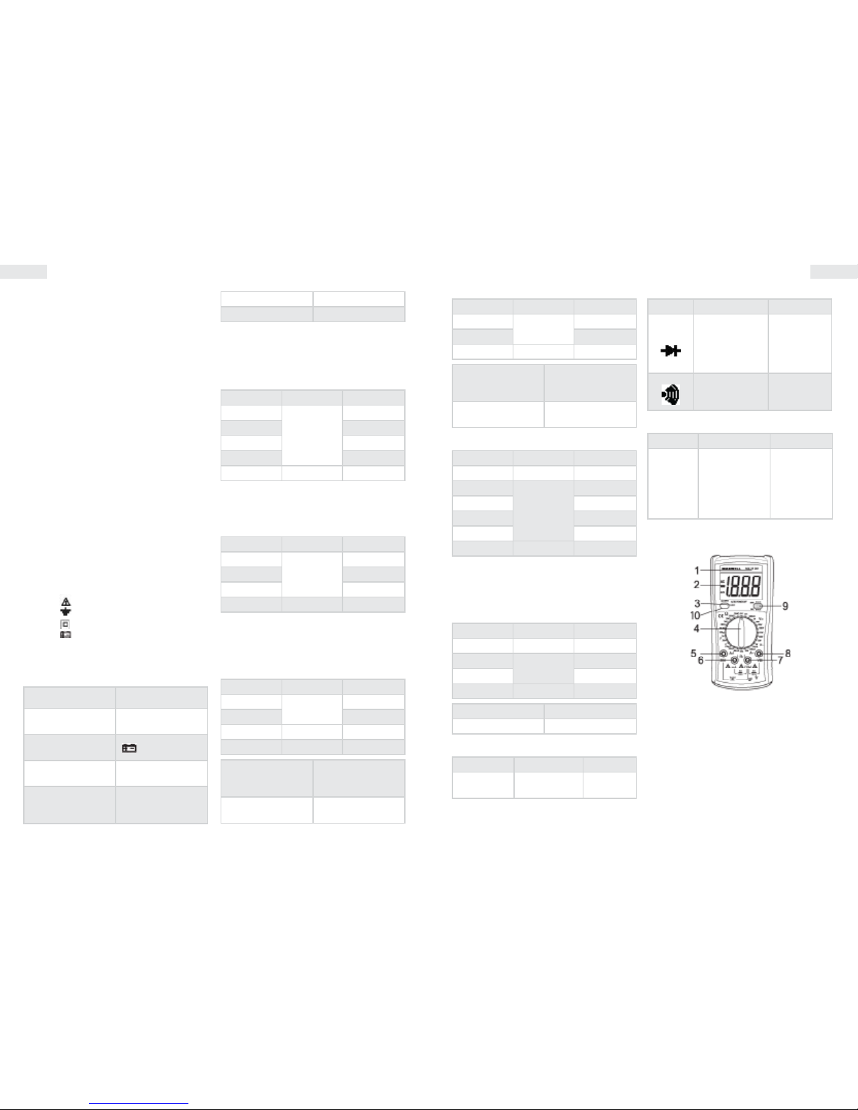
OperatiOn
1. Model no.
2. LCD display
3. Diode signal light
4. Function switch
5. „+” connector : 20A
6. „+” connector : mA+ capacity + temperature
7. „-” connector: ground (GND) + capacity+
temperature
8. „+” connector: voltage, resistance, diode,
continuity test
9. Transistor connector
10. Backlight/Auto Power O
Page 3
EN
User Manual User Manual
EN
DCV measuring
• Connect the black measuring wire to the
„COM” connector, and the red one to the „V/Ω”
connector.
• Set the function switch to the proper DCV
setting, and connect the wires to the circuit.
Note:
• If you are unsure about the measured voltage range, set
the function switch to a high range.
• If the LCD shows „1” it means overload, and the range
should be set to a higher value.
ACV measuring
• Connect the black measuring wire to the
„COM” connector, and the red one to the „V/Ω”
connector.
• Set the function switch to the proper ACV
setting and connect the wires to the circuit.
Note:
• If you are unsure about the measured voltage range, set
the function switch to a high range.
• If the LCD shows „1” it means overload, and the range
should be set to a higher value.
DCA measuring
• Connect the black measuring wire to the
„COM” connector, and the red one to the „mA”
connector (max. 200mA), or connect the red
wire to the „20A” connector (max. 20A).
• Set the function switch to the proper DCA
setting and connect the wires to the circuit.
Note:
• If you are unsure about the measured voltage range, set
the function switch to a high range.
• If the LCD shows „1” it means overload, and the range
should be set to a higher value.
• Max inward current 200mA or 20A (depending on the
placement of the red wire), in case of an exceeding
current the fuse will melt.
ACA measuring
• Connect the black measuring wire to the
„COM” connector, and the red one to the „V/Ω”
connector.
• Set the function switch to the proper ACA
setting, and connect the wires to the circuit.
Note:
• If you are unsure about the measured voltage range, set
the function switch to a high range.
• If the LCD shows „1” it means overload, and the range
should be set to a higher value.
• Max inward current 1000V.
Resistance measuring
• Connect the black measuring wire to the
„COM” connector and the red one to the V/Ω
connector.
• Set the function switch to the proper
resistance setting and connect the wires to the
measured resistor.
Note:
• If the measured resistance value is over the chosen max
value the LCD will show „1” and the function switch
needs to be set to a higher range. It may take a few
seconds for the device to stabilize when measuring
above 1MΩ
Capacity measuring
• Connect the wire to the „V/Ω „ connector and
the red one to the „COM” connector.
• Set the function switch to a proper capacity
setting and connect the wires to the measured
capacitor.
Note:
• If you are unsure about the measured capacity set the
function switch to a high range.
• If the LCD shows „1” it means overload and the function
switch needs to be set to a higher range.
• To be safe, discharge the measured capacitor before
measuring.
Diode and continuity test
• Connect the black measuring wire to the
„COM” connector, and the red one to the „V/Ω”
connector (Note: the red wire's polarity is „+”)
• Set the function switch to the „ ” position,
connect the wires to the measured diode.
• Connect the wires to the diode's measuring
points, if the device beeps, the resistance is
lower than appr. (70±20)Ω
Temperature measuring
• Connect the red wire to the mA, and the black
one to the "COM" connector. Touch the end
of the thermometer to the measured object
and the temperature value is displayed on the
screen in degrees Celsius.
hFE
• Set the function switch to hFE.
• Place the part into the transistor connector
depending on whether it is NPN or PNP type.
Automatic turn-o
• If the device is not used for 15 minutes it turns
o automatically. To use it again, turn the
function switch.
Background lighting
• Push the button „10” shortly to switch on or o
the background lighting.
Auto Power O
• Push the button „10” long to cancel the auto
power o function. If the inscription „APO”
appears on the display, the device does not
switch o automatically.
MaintenanCe
• Note that this device is not water-, dust- and
shock-resistant.
• Do not use and do not store the device at high
temperatures, in places with high humidity or
ammability or in strong magnetic elds.
• Do not use rough textile or alcohol.
• If the device is not being used for a longer
time period, the battery must be taken out.
Battery replacement (1 x 9V)
If the LCD display shows „ ” , the battery
needs to be replaced the following way:
• Take the device out of the plastic holder and
take o the battery holder cover.
• Take out the battery and replace it to a new
one. Use alkaline batteries if possible.
• Put the battery holder cover back.
Fuse replacement
• Only used the prescribed types of fuses for
replacing.
If the device does not operate properly,
check the following:
State Solution
Nothing is displayed
• Device is turned
o
• Replace the
battery
„
” is displayed
Replace the battery
No power Replace the fuse
Page 4

HU
Használati utasítás Használati utasítás
HU
Összegzés
A műszer széleskörű használata lehetővé teszi
DCV, ACV, DCA, ACA, ellenállás, kapacitás, dióda,
tranzisztor, folytonossági teszt és hőmérséklet
mérését. Használata ideális laboratóriumokban,
gyárakban és otthon is.
BiztOnsági Megjegyzés
A mérőműszer az IEC1010 szabványoknak
megfelel. Használat előtt gyelmesen olvassa el
a használati utasítást.
• Ne mérjen nagyobb értéket a beállított
méréshatárnál.
• Az elektromos áramütés elkerülése miatt
ellenőrizze, hogy a műszerzsinórok sérülés
mentesek legyenek.
• Helyezze át a műszerzsinórokat funkció
váltásakor.
• Válassza ki a helyes funkciót és méréshatárt,
kerülje el a hibás műveleteket.
• Ne használja a mérőműszert, ha az elemtartó
fedele és a hátlapja nincs a helyére rögzítve.
• Ellenállásmérés állásban ne mérjen
feszültséget.
• Húzza ki a vezetékeket és kapcsolja ki a
műszert, mielőtt kicseréli az elemet vagy a
biztosítékot.
• Biztonsági jelzések:
Fennáló veszélyes feszültség
Föld
Dupla szigetelés
Gyenge akkumulátor
jelleMzők
Kijelző LCD kijelzés
Max. kijelzés:
4 digites automatikus
polaritás kijelzéssel
Gyenge
akkumulátor
kijelzés
Működési környezet (0-40) °C, R. H. 80%.
Elem
9V X 1 (NEDA
1604/6F22 vagy
ugyanolyan típusú)
Méret 175 X 93 X 55 mm
Tömeg 400g (elemmel)
Műszaki adatOk
DCV
Méréshatár Pontosság Felbontás
200mV
±0.5%
100μV
2V 1mV
20V 10mV
200V 100mV
1000V ±0.8% 1V
Bemeneti ellenállás: 5mΩ mV tartományban, a
többi tartományban 10 mΩ
ACV
Méréshatár Pontosság Felbontás
2V
±0.8%
1mV
20V 10mV
200V 100mV
750V ±1.2% 1V
Bemeneti ellenállás: 10M Ω
Túlterhelés védelem: 1000V DC vagy AC
csúcsérték
Frekvencia átvitel :(40~200)Hz
DCA
Méréshatár Pontosság Felbontás
200μA
±0.8%
100nA
20mA 10μA
200mA ±1.2% 100μA
20A ±2.0% 10mA
Max. bemeneti
áramerősség
20A (a tesztidő
max.10 mp legyen)
Bizosíték
0,2A/250V és 20A /
250 V gyorsbiztosíték
ACA
Méréshatár Pontosság Felbontás
20mA
±(1.5%+5)
10μA
200mA 100μA
20A ±(3.0%+10) 10mA
Max. bemeneti
áramerősség
20A (a tesztidő
max.10 másodperc
legyen)
Bizosíték
0,2A/250V és 20A /
250 V gyorsbiztosíték
Ellenállás
Méréshatár Pontosság Felbontás
200Ω ±0.8% 0.1Ω
2kΩ
±0.8%
1Ω
20kΩ 10Ω
200kΩ 100Ω
2MΩ 1kΩ
20MΩ ±1.0% 10kΩ
FIGYELMEZTETÉS:
Ellenállás méréskor feszültséget ne mérjen!
Kapacitás
Méréshatár Pontosság Felbontás
2 nF ±(5.0%+40) 1pF
20nF
±(2.5%+20)
10pF
2-200μF 1-1000nF
2000μF ±(5.0%+10) 1 μF
Mérési frekvencia 150 Hz
Túlterhelés elleni
védelem
36 V DC / AC RMS
Hőmérséklet
Méréshatár Pontosság Felbontás
(-20~1000)°C
< 400°C±0,8%
> 400°C±1,5%
1°C
K típusú hőmérsékletmérő szenzorral
Dióda és folytonossági teszt
Funkció Leírás Teszt állapot
Nyító feszültség
A pozitív DC
áramerősség
kb. 1mA a
negatív feszült-
ség kb. 3V
Csipogó, ha az
ellenállás
kevesebb, mint
(70±20)Ω
Nyitott feszült-
ség kb. 3V
Trióda hFE teszt
Funkció Leírás Teszt állapot
hFE NPN
vagy PNP
0~1000
Nyitó
áramerősség
kb. 10μA
Nyitó feszült-
ség kb. 3V
MűkÖdés
1. Model szám
2. LCD kijelző
3. Dióda jelzőfény
4. Funkció kapcsoló
5. „+” bemeneti aljzat : 20A
6. „+” bemeneti aljzat : mA+ kapacitás +
hőmérséklet
7. „-” bemeneti aljzat : föld (GND) + kapacitás
+ hőmérséklet
8. „+” bemeneti aljzat : feszültség, ellenállás,
dióda, folyonosság teszt
9. Tranzisztor foglalat
10. Háttérvilágítás/Auto Power O kikapcsolás
Page 5

HU
Használati utasítás Használati utasítás
HU
DCV mérése
• Helyezze be a fekete műszerzsinórt a „COM”
aljzatba, a pirosat pedig a „V/Ω” aljzatba.
• Állítsa be a funkciókapcsolót a megfelelő DCV
fokozatba, csatlakoztassa a műszerzsinórokat
az áramkörhöz.
Megjegyzés:
• Ha nem biztos a mérendő feszültség értékében, állítsa a
funkciókapcsolót magasabb mérési fokozatba.
• Ha az LCD „1”- et mutat, ez túl nagy értéket jelent, és a
funkciókapcsolót egy magasabb fokozatba kell állítani.
ACV mérése
• Helyezze be a fekete műszerzsinórt a „COM”
aljzatba, a pirosat pedig a „V/Ω” aljzatba.
• Állítsa a funkciókapcsolót a megfelelő
ACV mérési fokozatba, csatlakoztassa a
műszerzsinórokat az áramkörhöz.
Megjegyzés:
• Ha nem biztos a mérendő feszültség értékében, állítsa a
funkciókapcsolót magasabb mérési fokozatba.
• Ha az LCD „1”- et mutat, ez túl nagy értéket jelent, és a
funkciókapcsolót egy magasabb fokozatba kell állítani.
DCA mérése
• Helyezze be a fekete műszerzsinórt a „COM”
aljzatba, a pirosat pedig az „mA” aljzatba (max.
200mA), vagy helyezze a piros műszerzsinórt a
„20A” aljzatba (max. 20A).
• Állítsa be a funkciókapcsolót a megfelelő DCA
fokozatba, csatlakoztassa a műszerzsinórokat
az áramkörhöz.
Megjegyzés:
• Ha nem biztos a mérendő áramerősség értékében,
állítsa a funkciókapcsolót magasabb mérési fokozatba
• Ha az LCD „1”- et mutat, ez túl magas értéket jelent, és a
funkciókapcsolót egy magasabb fokozatba kell állítani.
• Max. bemeneti áramerősség 200mA vagy 20A (attól
függ, hová van a piros műszerzsinór behelyezve), túlzott
áramerősség esetén kiolvad a biztosíték.
ACA mérése
• Helyezze be a fekete műszerzsinórt a „COM”
aljzatba, a pirosat pedig a „V/Ω” aljzatba.
• Állítsa be a funkciókapcsolót egy
megfelelő ACA fokozatba, csatlakoztassa a
műszerzsinórokat az áramkörhöz.
Megjegyzés:
• Ha nem biztos a mérendő feszültség értékében, állítsa a
funkciókapcsolót magasabb mérési fokozatba
• Ha az LCD „1”- et mutat, ez túl magas értéket jelent, és a
funkciókapcsolót egy magasabb fokozatba kell állítani.
• Max. bemeneti feszültség 1000V.
Ellenállás mérése
• Helyezze be a fekete műszerzsinórt a „COM”
aljzatba, a pirosat pedig a V/Ω aljzatba.
• Állítsa be a funkciókapcsolót egy megfelelő
ellenállás fokozatba, csatlakoztassa a
műszerzsinórokat a mérendő ellenálláshoz.
Megjegyzés:
• Ha mért ellenállás értéke túllép a kiválasztott maximum
értéken, az LCD „1”- et mutat, így a funkciókapcsolót egy
magasabb fokozatba kell állítani. Amikor az ellenállás
1MΩ felett van, akkor a műszernek eltarthat néhány
másodpercig a stabilizálás.
Kapacitás mérése
• Helyezze a műszerzsinórt a „V/Ω „ csatlakozó
aljzatba, és a feketét pedig a „COM” aljzatba.
• Állítsa a funkciókapcsolót egy megfelelő
kapacitású fokozatba, csatlakoztassa a
műszerzsinórokat a mérendő kondenzátorhoz.
Megjegyzés:
• Ha nem biztos a mérendő kapacitás értékében, állítsa a
funkciókapcsolót magasabb mérési fokozatba
• Ha az LCD „1”- et mutat, ez túl magas értéket jelent, és a
funkciókapcsolót egy magasabb fokozatba kell állítani.
• Kapacitás mérése előtt a biztonság kedvéért a mérendő
kondenzátort süsse ki
Dióda és folytonossági teszt
• Helyezze a fekete műszerzsinórt a „COM”
aljzatba, a pirosat pedig a „V/Ω” aljzatba.
(Megjegyzés: a piros műszerzsinór polaritása:
„+”)
• Állítsa a funkciókapcsolót „ ” fokozatba,
csatlakoztassa a műszerzsinórokat a mérendő
diódára.
• Csatlakoztassa a műszerzsinórokat az alkatrész
két pontjához, ha a műszer sípol, akkor az
ellenállás kisebb, mint kb. (70±20)Ω
Hőmérséklet mérése
• Helyezze a piros mérőzsinórt a mA , a
feketét pedig a COM bemeneti aljzatba. A
hőmérő véget érintse a mérendő tárgyhoz, a
hőmérséklet értékét le lehet olvasni az LCD-ről
Celsiusban.
hFE
• Állítsa a funkciókapcsolót hFE-be.
• Helyezze az alkatrészt a tranzisztor foglalatba
ügyelve arra, hogy NPN vagy PNP fajta.
Automatikus kikapcsolás
• Ha a műszert 15 percig nem használjuk, akkor
automatikusan kikapcsol. Az újraindításhoz
forgassa el a funkciókapcsolót.
Háttérvilágítás
• Nyomja meg a 10-es gombot röviden a
háttérvilágítás be-, illetve kikapcsolásához.
Auto Power O
• Nyomja meg a 10-es gombot hosszan
az automata kikapcsolás funkció
érvénytelenítéséhez. Ha a kijelzőn az "APO"
felirat látható a készülék nem kapcsol ki
automatikusan.
karBantartás
• Vegye gyelembe, hogy a műszer nem vízálló,
porálló és ütésálló.
• Ne használja és ne tárolja a műszert magas
hőmérsékleten, nagy páratartalmú és
lobbanékony helyen, vagy erős mágneses
területen.
• Ne használjon érdes ruhát és alkoholt.
• Ha a műszer sokáig nem működik, akkor ki kell
venni az elemet.
Elemcsere (1 db 9V-os)
Ha az LCD kijelző „ ” -t mutat, akkor ki kell
cserélni az elemet az alábbi módon:
• Vegye ki a műanyag tokból és vegye le az
elemtartót.
• Vegye ki az elemet, és cserélje ki egy újra.
Használjon tartós elemet.
• Rögzítse az elemtartót, és tegye vissza a
műanyag tokot
Biztosítékcsere
• Biztosíték kicserélésére csak az előírt típust
használja.
Ha a műszer nem megfelelően működik,
akkor az alábbi módon ellenőrizze a műszert
Állapot Megoldás
Nincs kijelzés
• Ki van kapcsolva
a műszer
• Cserélje ki az
elemet
„
” jelenik meg
Cserélje ki az elemet
Nem kap áramot
Cserélje ki a
biztosítékot
Page 6

RO
Manual de utilizare Manual de utilizare
RO
rezUMat
Deoarece instrumentul este de gamă largă
îl putem utiliza la măsurare DCV, ACV, DCA,
ACA, rezistenţă, capacitate, diode, tranzistoare,
continuitate şi temperatură. Utilizarea lui este
ideal în laboratoare, fabrici şi chiar acasă.
nOtă de sigUranţă
Instrumentul îndeplineşte standardele IEC1010.
Citiţi cu atenţie instrucţiunile de utilizare înainte
de folosire.
• Nu măsuraţi valoare mai mare decât domeniul
de măsurat stabilit.
• Pentru evitarea electrocutării vericaţi
cablurile de măsurat să nu e vătămaţi.
• Când schimbaţi funcţia aşezaţi cablurile de
măsurat la contactul potrivit funcţiei.
• Alegeţi funcţia şi domeniul de măsurat corect,
evitaţi operaţiunile greşite.
• Nu utilizaţi instrumentul dacă capacul
compartimentului bateriei şi capacul din spate
nu sunt xate la loc.
• În modul de măsurare rezistenţă nu măsuraţi
tensiune.
• Îndepărtaţi cablurile de măsurat şi opriţi
instrumentul înainte să schimbaţi bateria sau
fuzibilul.
• Marcaje de siguranţă:
Prezenţa tensiunii periculoase
Masă
Izolaţie dublă
Baterie descărcată
prOprietăţi
Aşaj Aşaj LCD
Aşare maximă:
4 cifre cu indicarea
polarităţii automatică
Indicare baterie
descărcată
Ambianţă de lucru (0-40) °C, R. H. 80%.
Baterie
1buc 9V (NEDA
1604/6F22 sau de
acelaşi tip)
Mărime 175 x 93 x 55 mm
Greutate 400g (cu baterie)
date teHniCe
DCV
Domeniu de
măsurat
Acurateţe Rezoluţie
200mV
±0.5%
100μV
2V 1mV
20V 10mV
200V 100mV
1000V ±0.8% 1V
Impedanţa de intrare: 5 mΩ în domeniul mV, 10
mΩ în restul domeniilor
ACV
Domeniu de
măsurat
Acurateţe Rezoluţie
2V
±0.8%
1mV
20V 10mV
200V 100mV
750V ±1.2% 1V
Impedanţa de intrare: 10M Ω
Protecţia la supratensiune: 1000 V CC, sau
valoare de vârf CA
Domeniu de frecvenţă: (40~200) Hz
DCA
Domeniu de
măsurat
Acurateţe Rezoluţie
200μA
±0.8%
100nA
20mA 10μA
200mA ±1.2% 100μA
20A ±2.0% 10mA
Curent max. de
intrare
20A (timpul de test
max.10sec să e)
Fuzibil
0,2A/250V şi 20A /
250 V fuzibil rapid
ACA
Domeniu de
măsurat
Acurateţe Rezoluţie
20mA
±(1.5%+5)
10μA
200mA 100μA
20A ±(3.0%+10) 10mA
Curent max. de
intrare
20A (timpul de test
max.10sec să e)
Fuzibil
0,2A/250V şi 20A /
250 V fuzibil rapid
Rezistenţă
Domeniu de
măsurat
Acurateţe Rezoluţie
200Ω ±0.8% 0.1Ω
2kΩ
±0.8%
1Ω
20kΩ 10Ω
200kΩ 100Ω
2MΩ 1kΩ
20MΩ ±1.0% 10kΩ
ATENŢIE: La modul de măsurare rezistenţă nu
măsuraţi tensiune!
Capacitate
Domeniu de
măsurat
Acurateţe
Rezoluţie
2 nF ±(5.0%+40) 1pF
20nF
±(2.5%+20)
10pF
2-200μF 1-1000nF
2000μF ±(5.0%+10) 1 μF
Frecvenţa de măsurat 150 Hz
Protecţie împotriva
suprasarcinii
36 V DC / AC RMS
Temperatură
Domeniu de
măsurat
Acurateţe Rezoluţie
(-20~1000)°C
< 400°C±0,8%
> 400°C±1,5%
1°C
Cu termocuplă de tip K
Test de diode şi continuitate
Funcţie Descriere Stare test
Tensiune de
deschidere
Curentul
pozitiv DC cca.
1mA, tensiunea
negativă cca.
3V
Piuie dacă
rezistenţa este
mai mică de
(70±20)Ω
Tensiunea
deschisă cca.
3V
Test triodă hFE
Funcţie Descriere Stare test
hFE NPN
sau PNP
0~1000
Curent de
deschidere
cca. 10μA
Tensiune de
deschidere
cca. 3V
fUnCţiOnare
1. Nr model
2. Aşaj LCD
3. Lumină indicatoare diodă
Page 7

RO
Manual de utilizare Manual de utilizare
RO
4. Comutator funcţii
5. „„+” banană de intrare : 20A
6. „+” banană de intrare : mA+ condensator +
temperatură
7. „-” banană de intrare : masă (GND) +
condensator + temperatură
8. „+” banană de intrare : tensiune, rezistenţă,
diodă, test de continuitate
9. Soclu tranzistor
10. Lumina de fundal/Auto Power O
Măsurare DCV
• Aşezaţi cablul de măsurat negru la „COM” iar
cel roşu la „V/Ω”.
• Rotiţi comutatorul de funcţii la domeniul
potrivit DCV, conectaţi cablurile de măsurat la
circuit.
Notă:
• Dacă nu sunteţi sigur în valoarea tensiunii ce va
măsurat, aşezaţi comutatorul de funcţii la un domeniu
superior.
• Dacă aşajul LCD arată „1”înseamnă că valoarea este
prea mare şi trebuie să comutaţi comutatorul de funcţii
la un domeniu mai mare.
Măsurare ACV
• Aşezaţi cablul de măsurat negru la „COM” iar
cel roşu la „V/Ω”.
• Rotiţi comutatorul de funcţii la domeniul
potrivit ACV, conectaţi cablurile de măsurat la
circuit.
Notă:
• Dacă nu sunteţi sigur în valoarea tensiunii ce va
măsurat, aşezaţi comutatorul de funcţii la un domeniu
superior.
• Dacă aşajul LCD arată „1”înseamnă că valoarea este
prea mare şi trebuie să comutaţi comutatorul de funcţii
la un domeniu mai mare.
Măsurare DCA
• Aşezaţi cablul de măsurat negru la „COM” iar
cel roşu la „mA” (max. 200mA) sau la „20A”
(max. 20A).
• Rotiţi comutatorul de funcţii la domeniul
potrivit DCA, conectaţi cablurile de măsurat la
circuit.
Notă:
• Dacă nu sunteţi sigur în valoarea curentului ce va
măsurat, aşezaţi comutatorul de funcţii la un domeniu
superior.
• Dacă aşajul LCD arată „1”înseamnă că valoarea este
prea mare şi trebuie să comutaţi comutatorul de funcţii
la un domeniu mai mare.
• Curentul maxim de intrare 200mA sau 20A (în funcţie
de unde este conectat cablul roşu de măsurat), în caz de
curent exagerat se topeşte fuzibilul
Măsurare ACA
• Aşezaţi cablul de măsurat negru la „COM” iar
cel roşu la „V/Ω”.
• Rotiţi comutatorul de funcţii la domeniul
potrivit ACA, conectaţi cablurile de măsurat la
circuit.
Notă:
• Dacă nu sunteţi sigur în valoarea curentului ce va
măsurat, aşezaţi comutatorul de funcţii la un domeniu
superior.
• Dacă aşajul LCD arată „1”înseamnă că valoarea este
prea mare şi trebuie să comutaţi comutatorul de funcţii
la un domeniu mai mare.
• Curentul maxim de intrare 200mA sau 20A (în funcţie
de unde este conectat cablul roşu de măsurat), în caz de
curent exagerat se topeşte fuzibilul.
• Tensiunea maximă este 1000V
Măsurare rezistenţă
• Aşezaţi cablul de măsurat negru la „COM” iar
cel roşu la „V/Ω”.
• Rotiţi comutatorul de funcţii la domeniul
potrivit de rezistenţă, conectaţi cablurile de
măsurat la rezistor.
Notă:
• Dacă valoarea rezistorului depăşeşte domeniul ales,
aşorul LCD va indica „1”. Comutatorul de funcţii trebuie
să aşezaţi la un domeniu superior. Când rezistorul are
valoare peste 1MΩ instrumentul va avea nevoie câteva
secunde până la stabilire
Măsurare capacitate
• Aşezaţi cablul de măsurat negru la „COM” iar
cel roşu la „V/Ω”.
• Rotiţi comutatorul de funcţii la domeniul
potrivit de capacitate, conectaţi cablurile de
măsurat la condensator.
Notă:
• Dacă nu sunteţi sigur de valoarea condensatorului
aşezaţi comutatorul de funcţii la un domeniu de măsurat
superior
• Dacă aşorul LCD indică „1” aveţi valoare prea mare şi
comutatorul de funcţii trebuie să mutaţi la un domeniu
de măsurat mai mare.
• Înainte de măsurare capacitate pentru siguranţă
descărcaţi condensatorul ce doriţi să măsuraţi
Test de diodă şi continuitate
• Aşezaţi cablul de măsurat negru la „COM” iar
cel roşu la „V/Ω”. (Notă: polaritatea cablului de
măsurat roşu este: „+”)
• Rotiţi comutatorul de funcţii la „ ”,
conectaţi cablurile de măsurat la dioda ce
măsuraţi.
• Conectaţi cablurile de măsurat la circuitul
testat. Dacă instrumentul piuie rezistenţa
circuitului este mai mică de cca. (70±20)Ω
Măsurare temperatură
• Aşezaţi cablul de măsurat negru la „COM” iar
cel roşu la mA. Vârful termocuplei atingeţi la
obiectul testat. Temperatura se poate citi de pe
aşajul LCD în grade Celsius
hFE
• Rotiţi comutatorul de funcţii la poziţia hFE.
• Aşezaţi componentul în soclul de tranzistor
având grijă la tipul lui NPN sau PNP.
Oprire automată
• Dacă instrumentul nu folosiţi timp de 15
minute, se opreşte automat. Pentru repornire
rotiţi comutatorul de funcţii.
Lumină de fundal
• Apăsați scurt butonul 10 pentru a porni- sau
opri lumina de fundal
Orpire automata (Auto Power OFF)
• Apăsați lung butonul 10 pentru validarea
funcției de Oprire Automată. Aparatul nu se
va opri automat dacă pe ecran este așată
inscripția ”APO” .
Întreţinere
• Ţineţi cont de faptul că instrumentul nu e
rezistent la apă, praf şi lovituri.
• Nu utilizaţi şi nu depozitaţi instrumentul la
temperaturi ridicate, la umiditate relativă
ridicată şi locuri inamabile sau loc puternic
magnetizat.
• Nu utilizaţi cârpă dură şi spirt.
• Dacă instrumentul nu funcţionează timp
îndelungat trebuie să scoateţi bateria
Schimbarea bateriei (1 buc tip 9V)
Dacă aşajul LCD indică „ ” trebuie să
schimbaţi bateria în felul următor:
• Scoateţi din husa din plastic şi demontaţi
capacul compartimentului bateriei.
• Scoateţi bateria şi schimbaţi cu unul nou.
Folosiţi baterie durabilă.
• Fixaţi compartimentul bateriei şi asamblaţi
înapoi husa din plastic.
Schimbarea siguranţei
• Pentru schimbarea fuzibilului folosiţi doar tipul
specicat
Dacă instrumentul nu funcţionează corect
vericaţi instrumentul în felul următor
Stare Soluţie
Nu este aşare
• Instrumentul
este oprit
• Schimbaţi
bateria
„
” apare pe aşaj
Schimbaţi bateria
Nu primeşte curent Schimbaţi siguranţa
Page 8

SK
Uživateľská príručka Uživateľská príručka
SK
preHľad
Rozsiahle využívanie prístroja dá možnosť na
meranie odporu, DCV, ACV, DCA, ACA, kapacity,
diódy, tranzistora, testu kontinuity a teploty.
Ideálne použitie v laboratóriumoch , továrni a v
dome.
BezpečnOstné pOznáMky
Prístroj splňa normy IEC1010 . Pred používanie
si prečítajte návod na použitie pozorne.
• Nemerajte väčšiu hodnotu, ako je nastavený
merací limit.
• Aby sa zabránilo elektrického šoku, kontrolujte
šnúry prístroja, či sú v dobrom stave.
• Presuňte šnúry prístroja u prepnuitie funkcií.
• Vyberte správnú funkciu a meracíeho limita a
vyhnite si chybných operácií.
• Nepoužite prístroj, ak predný a zadný panel
držiaka batérií nie je dobre uzavretý.
• Nemerajte napätie v polohe meranie odporu.
• Vyťiahnite káble, a vypnite prístroj pred
výmenu batérií alebo poistok.
• Bezpečnostné označenie:
Nebezpečné napätie
Pôda
Dvojitá izolácia
Slabý akumulátor
fUnkCie
Displej LCD displej
Max. zobrazenie:
4 digitový s
automatickým
zobrazením polarity
Zobrazenie slabého
akumulátora
Prevádzkové
prostredie
(0-40) °C, R. H. 80%.
Batéria
9V X 1 (NEDA
1604/6F22 alebo taký
istý typ)
Rozmery 175 X 93 X 55mm
Váha 400g (s batériou)
teCHniCké údaje
DCV
Merací rozsah Presnosť Rozlíšenie
200mV
±0.5%
100μV
2V 1mV
20V 10mV
200V 100mV
1000V ±0.8% 1V
Vstupný odpor: 5mΩ v mV rozsahu, pri
ostatných rozsahoch 10 mΩ
ACV
Merací rozsah Presnosť Rozlíšenie
2V
±0.8%
1mV
20V 10mV
200V 100mV
750V ±1.2% 1V
Vstupný odpor: 10M Ω
Ochrana proti preťaženiu: 1000V DC alebo AC
napäťové špičky
Frekvenčná odozva:(40~200)Hz
DCA
Merací rozsah Presnosť Rozlíšenie
200μA
±0.8%
100nA
20mA 10μA
200mA ±1.2% 100μA
20A ±2.0% 10mA
Max. vstupná sila
prúdu
20A (doba testovanie
max.10 s)
Poistka
0,2A/250V a 20A /
250 V rýchlo poistka
ACA
Merací rozsah Presnosť Rozlíšenie
20mA
±(1.5%+5)
10μA
200mA 100μA
20A ±(3.0%+10) 10mA
Max. vstupná sila
prúdu
20A (doba testovanie
max.10 s)
Poistka
0,2A/250V a 20A /
250 V rýchlo poistka
Odpor
Merací rozsah Presnosť Rozlíšenie
200Ω ±0.8% 0.1Ω
2kΩ
±0.8%
1Ω
20kΩ 10Ω
200kΩ 100Ω
2MΩ 1kΩ
20MΩ ±1.0% 10kΩ
UPOZORNENIE:
Nemerajte napätie u meranie opdoru!
Kapacita
Merací rozsah Presnosť Rozlíšenie
2 nF ±(5.0%+40) 1pF
20nF
±(2.5%+20)
10pF
2-200μF 1-1000nF
2000μF ±(5.0%+10) 1 μF
Meracia frekvencia 150 Hz
Ochrana proti
preťaženiu
36 V DC / AC RMS
Teplota
Merací rozsah Presnosť Rozlíšenie
(-20~1000)°C
< 400°C±0,8%
> 400°C±1,5%
1°C
So senzorom teplomeru typu K
Test diódy a kontinuity
Funkcia Opis Testovací stav
Počiatočné
napätie
Pozitívna
sila prúdu
DC o. 1mA
a negatívné
napätie o. 3V
Pípanie, ak odpor
je menej, ako
(70±20)Ω
Počiatočné
napätie o. 3V
Test Triódy hFE
Funkcia Opis
Testovací
stav
hFE NPN
alebo PNP
0~1000
Počiatočná
sila prúdu
o. 10μA
Počiatočné
napätie o. 3V
prevádzka
1. Číslo modelu
2. LCD displej
3. Diódové signalizačné svetlo
4. Spínač funkcií
5. „+” vstupná zásuvka : 20A
6. „+” vstupná zásuvka : mA+ kapacita +
teplota
7. „-” vstupná zásuvka : pôda (GND) +
kapacita + teplota
8. „+” vstupná zásuvka : napätie, odpor, dióda,
test continuity,
9. Tranzistorová zásuvka
10. Podsvietenie/Auto Power O
Page 9

SK
Uživateľská príručka Uživateľská príručka
SK
DCV meranie
• Vložte čierne šnúry prístroja do zásuvky „COM”,
a červené do zásvuky „V/Ω”.
• Nastavte spínača funkcií na správnej
úrovni,DCV a pripojte šnúry prístroja k obvodu.
Poznámka:
• Ak nie ste istý v hodnote meraného napätia, nastavte
spínača funkcií na vyššý merací úroveň.
• Ak LCD zobrazí nápis„1”, to znamená prílliš veľkú
hodnotu, vtedy si musíte nastaviť spínača funckií do
vyššej úrovni
ACV meranie
• Vložte čierne šnúry prístroja do zásuvky„COM” ,
a červené do zásuvky „V/Ω” .
• Nastavte spínača funckií na správnej meraciej
úrovni ACV, a pripojte šnúry prístroja k obvodu
Poznámka:
• Ak nie ste istý v hodnote meraného napätia, nastavte
spínača funkcií na vyššý merací úroveň.
• Ak LCD zobrazí nápis„1”, to znamená prílliš veľkú
hodnotu, vtedy si musíte nastaviť spínača funckií do
vyššej úrovni.
DCA meranie
• Vložte čierne šnúry prístroja do zásvuky „COM”
, a červené do zásuvky „mA” (max. 200mA),
alebo vložte červené šnúry prístroja do
zásuvky „20A” (max. 20A).
• Nastavte spínača funckií na vhodnej úrovni
DCA, pripojte šnúry prístroja k obvode.
Poznámka:
• Ak nie ste istý v hodnote meraného silu prúdu, nastavte
spínača funkciu na vyššý merací úroveň.
• Ak LCD zobrazí nápis „1”,to znamená príliš vysokú
hodnotu, a vtedy musíte nastaviť spínača funkcií do
vyššej úrovni.
• Max. vstupná sila prúdu je 200mA alebo 20A (závisí
od toho, kde je červená šnúra prístroja pripojená), u
prípade príliš veľkej silu prúdu poistka sa rozpúšťí
ACA meranie
• Vložte čierne šnúry prístroja do zásuvky „COM”,
a červené do zásvuky „V/Ω”.
• Nastavte spínača funkcií do správnej
úrovni,ACA a pripojte šnúry prístroja k obvodu.
Poznámka:
• Ak nie ste istý v hodnote meraného napätia, nastavte
spínača funkcií na vyššý merací úroveň.
• Ak LCD zobrazí nápis„1”, to znamená príliš veľkú
hodnotu, vtedy musíte nastaviť spínača funckií do
vyššej úrovni.
• Max. vstupné napätie 1000V
Meranie odporu
• Vložte čierne šnúry prístroja do zásuvky „COM”,
a červené do zásvuky „V/Ω”.
• Nastavte spínača funkcií do vhodnej úrovni
odporu a pripojte šnúry prístroja k meraného
odporu.
Poznámka:
• Ak nameraná hodnota prestúpí na vybrané maimálnu
hodnotu, LCD zobrazí nápis „1”, vtedy spínača funkcií
si musite nastaviť na vyššý úroveň. Ak odpor je nad
1MΩ, tak prístroj potrebuje niekoľkých minút na
stabilizovanie.
Meranie kapacít
• Vložte čierne šnúry prístroja do zásuvky „COM”,
a červené do zásvuky „V/Ω”.
• Vložte šnúry prístroja do konektorovej zásuvky
„V/Ω , a čierne do zásuvky „COM”.
• Nastavte spínača funkcií na úrovni s vhodnou
kapacitou, a pripojte šnúry prístroja k
meraného kondenzátora.
Poznámka:
• Ak nie ste istý v hodnote meranej kapacity, nastavte
spínača funkcií na vyšší merací úroveň.
• Ak LCD zobrazí nápis „1”, vtedy spínača funkcií si musite
nastaviť na vyššý úroveň.
• Pred meranie kapacitu vybite meraného kondenzátora
kvôli bezpečnosťi
Test diódy a kontinuity
• Vložte čierne šnúry prístroja do zásuvky
„COM”, a červené do zásuvky„V/Ω” . (Poznámka:
polarita červenej šnúry prístroja: „+”)
• Nastavte spínača funkcií do polohe „ ”
pripojte šnúry prístroja k meranej diode.
• Pripojte šnúry prístroja k dvoch bodov
súčiastok, ak prístroj pípne, odpor je menší,
ako (70±20)Ω.
Meranie teplotu
• Vložte červené šnúry prístroja do vstupnej
zásuvky mA , a čierne do COM. Koncovky
teplomeru pripojte k meraného objektu a a
hodnotu meranie si môžete sčítať z LCD v °
Celsius.
hFE
• Nastavte spínača funkcií do hFE.
• Vložte súčiastky do zásuvky tranzistora, ale
pozorte na to, či je typ NPN alebo PNP
Automatické vypnutie
• Ak prístroj nepoužívate po 15 minút,
automaticky vypína. Pre reštartovanie natáčte
spínača funkcií.
Podsvietenie
• Stlačte krátko po sebe 10 krát tlačítko pre
vypnutie alebo zapnutie podsvietenia.
Vypnutie automatického vypínania
• Stlačte 10 krát po sebe dlhšie tlačítko pre
vypnutie funkcie automatického vypnutia.
Ak na displeji svieti nápis "APO" potom sa
zariadenie nebude samo automaticky vypínať.
údržBa
• Zapametajte si, že prístroj nie je vodotesný
alebo odoľný proti prachu a úderu
• Nepoužívajte a neskladajte prístroj na vysokú
teplotu, v horľavom priestoru s vysokou
vlhkosťou páry ,alebo silnou magnetizáciou,.
• Nepoužívajte alcohol alebo hrubú handru .
• Ak prístrpj nie je v prevádzku po dlhší čas,
musíte si vybrať batérie
Výmena batérie (1 ks typu 9V)
Ak LCD zobrazí nápis „ ” vtedy si musíte
vymeniť batérie podľa nasledovných:
• Vyberte z plastového krytu a odstráňte držiaka
batérií.
• Vyberte batérie a vymeňte ich na nové. Použite
trvanlivé batérie.
• Upevnite držiaka batérií a dajte naspäť
plastový kryt
Výmena batérií
• Použite predpísaný typ u výmenu poistok.
Ak prístroj nefunguje poriadne, kontrolujte
prístroj podľa nasledovných:
Stav Riešenie
Nie je zobrazenie
• Prístroj je
vypnutý
• Vymeňte batérie
„
” sa objavý
Vymeňte batérie
Nie je dostatok prúdu Vymeňte poistky
 Loading...