

Page 1

MaxPac Dual/Triple-Screen
8230 XRA2/3-Series
User Operation and Maintenance Guide
Operating and Maintaining Your
MaxPac Dual/Triple-Screen 8230 XRA2/3-Series
High-Performance Transportable Workstation
MaxVision Corporation
495 Production Avenue
Madison, AL 35758, USA
Part Number: 209-0048-0
Page 2

ii MaxPac Dual/Triple-Screen 8230 XRA2/3-Series User Operation and Maintenance Guide
Warranties and Liabilities
MaxVision Corporation warrants that the Product, in the course of its normal use, will conform to MaxVision's
specifications and be free from defects in material and workmanship for a period of twelve (12) months from the date of
the original sale. Such warranty commences on the purchase date appearing on the invoice. The original end user is
entitled to customer support through telecommunication during normal MaxVision business hours and email support to be
responded to as support staff are available. Such support shall be limited to hardware operations and the software
required operating such hardware. Upon written request and subject to the availability of MaxVision personnel, additional
support may be provided by MaxVision in its sole discretion on a time and materials basis.
Limited Warranty for Software. MaxVision warrants to the original end user only that the Software as delivered at the
time of purchase will perform in MaxVision hardware, and that the original diskettes or compact disks are free from
defects in material and workmanship under normal use, for a period of thirty (30) days from the date of original sale,
provided the Software is used with a MaxVision unit. MaxVision makes no warranty that the Software will work in
combination with any hardware or software products provided by third parties, that the operation of the Software will be
uninterrupted or error-free, or that all defects in the Software will be corrected. This limited warranty is void if failure of the
Software has resulted from accident, abuse, or misapplication. MaxVision's entire liability, and your sole and exclusive
remedy shall be, at MaxVision's option, either to (a) correct or help you work around or avoid a reproducible Error or (b)
replace defective diskettes or compact disks. Any replacement Software will be warranted for the remainder of the original
Limited Software Warranty Period.
Limited Warranty for the Product. MaxVision warrants to the original end user only that all Products sold by MaxVision
will be free from defects in material and workmanship and conform substantially to the applicable standards set forth in
the Documentation, under normal use, for a period of 365 days from the date of original sale. This limited warranty is void
if failure of the Product has resulted from accident, abuse, or misapplication. If MaxVision confirms a Product is defective
after you have obtained a Return Materials Allowance Number for such Product and, at your expense, have returned the
Product to MaxVision for inspection, MaxVision will, at its election, repair or replace such Product at no charge to you.
Replacement Product may be either new or remanufactured. In the event that the Product returned is not defective, you
will be responsible for freight costs for return shipment to you. The foregoing warranty shall not apply to Product that has
been (a) damaged by accident, Acts of God, shipment, improper installation, abnormal physical or electrical stress,
misuse or misapplication, as determined by MaxVision in its sole reasonable discretion, or (b) modified without
MaxVision's express written acceptance of such modification for warranty purposes. MaxVision reserves the right to
charge additional fees for repairs or replacements performed outside the Warranty Period. Any replaced or repaired
components, subassemblies or units as well as spare parts are warranted for thirty (30) days or the remainder of the
original warranty period, whichever is longer. MaxVision shall not be responsible for any software, firmware, information or
memory data of yours contained in, stored on, or integrated with any Products returned to MaxVision pursuant to any
warranty under this Agreement.
Disclaimer of Warranties. EXCEPT AS SPECIFICALLY PROVIDED ABOVE, NEITHER MAXVISION NOR ITS
LICENSORS OR SUPPLIERS PROVIDES ANY WARRANTY OF ANY KIND FOR THE SOFTWARE OR THE
PRODUCT, WHETHER EXPRESS, IMPLIED, STATUTORY OR OTHERWISE, INCLUDING BUT NOT LIMITED TO
WARRANTIES OF MERCHANTABILITY, FITNESS FOR A PARTICULAR PURPOSE, AND NON-INFRINGEMENT OF
THIRD PARTY RIGHTS. EXCEPT AS SET FORTH IN THIS AGREEMENT, THE ENTIRE RISK AS TO THE QUALITY
AND PERFORMANCE OF THE SOFTWARE AND THE PRODUCT IS WITH YOU. If a disclaimer of implied warranties is
not permitted by law, the duration of any such implied warranty is limited to ninety (90) days from the date of purchase by
the original end user. Some jurisdictions do not allow the exclusion of implied warranties or limitations on how long an
implied warranty may last, so such limitations or exclusions may not apply to you. This limited warranty gives you specific
legal rights, and you may also have other rights which vary from jurisdiction to jurisdiction.
Liability Exclusions and Limitations. IN NO EVENT SHALL MAXVISION OR ITS LICENSORS OR SUPPLIERS BE
LIABLE FOR ANY INDIRECT, SPECIAL, INCIDENTAL, EXEMPLARY OR CONSEQUENTIAL DAMAGES OF ANY KIND
(INCLUDING LOST PROFITS, LOSS OF USE OR INTERRUPTION OF BUSINESS), OR FOR LEGAL FEES, ARISING
OUT OF THE USE OF THE SOFTWARE OR THE PRODUCT, REGARDLESS OF THE FORM OF ACTION, WHETHER
IN CONTRACT, TORT (INCLUDING NEGLIGENCE), STRICT PRODUCT LIABILITY OR OTHERWISE, EVEN IF
MAXVISION OR ITS LICENSORS OR SUPPLIERS HAVE BEEN ADVISED OF THE POSSIBILITY OF SUCH
DAMAGES. IN NO EVENT WILL COMPANY'S AGGREGATE LIABILITY HEREUNDER EXCEED THE PURCHASE
PRICE PAID BY YOU. This limitation shall apply notwithstanding any failure or inability to provide the limited remedies set
forth above. Some jurisdictions do not allow the exclusion or limitation of incidental or consequential damages, so the
above limitation(s) or exclusion(s) may not apply to you.
Page 3

MaxPac Dual/Triple-Screen 8230 XRA2/3-Series User Operation and Maintenance Guide iii
Proprietary Rights-Contracts with Certain U.S. Government Agencies. If the Software is acquired under the terms of
a Department of Defense or civilian agency contract, the Software is "commercial item" as that term is defined at 48
C.F.R. 2.101 (Oct. 1995), consisting of "commercial computer software" and "commercial computer software
documentation" as such terms are used in 48 C.F.R. 12.212 of the Federal Acquisition Regulations and its successors
and 48 C.F.R. 227.7202-1 through 227.7202-4 (June 1995) of the DoD FAR Supplement and its successors. All U.S.
Government end users acquire the Software with only those rights set forth in this Agreement.
Export Restrictions. You acknowledge that the laws and regulations of the United States restrict the export and re-export
of certain commodities and technical data of United States origin, including the Product and the Software, in any medium.
You agree that you will not knowingly, without prior authorization if required, export or re-export the Software or the
Product in any medium without the appropriate United States and foreign government licenses.
Severability. You acknowledge and agree that each provision of this Agreement that provides for a disclaimer of
warranties or an exclusion or limitation of damages represents an express allocation of risk, and is part of the
consideration of this Agreement. Invalidity of any provision of this Agreement shall not affect the validity of the remaining
provisions of this Agreement.
General. This Agreement is the entire agreement between you and MaxVision relative to the Product and the Software,
and supersedes all prior written statements, proposals or agreements relative to its subject matter. It may be modified only
by a writing executed by an authorized representative of MaxVision. No MaxVision reseller or sales representative is
authorized to make any modifications, extensions or additions to this Agreement. This Agreement is governed by the laws
of the State of Alabama without application of the principles of conflicts or choice of laws. The application of the United
Nations Convention on Contracts for the International Sale of Goods to this Agreement is expressly excluded.
Copyright
The materials in this document are the copyrighted works of MaxVision Corporation, copyright © 2005-2006. All rights
reserved. Email [email protected] for permission to duplicate and otherwise re-use.
Trademarks
MaxVision, and MaxPac are registered trademarks, and MaxPro and TeraPac are trademarks, of MaxVision Corporation.
Microsoft and Windows are registered trademarks of Microsoft Corporation. Intel and Pentium are registered trademarks
and Xeon is a registered trademark of Intel Corporation. Other trademarks and registered trademarks are the property of
their respective owners.
Regulatory Approvals
EN60950, EN55024, EN55022, FCC, Part 15, EN61000-3-2 & EN61000-3-3.
Warnings
Changes or modifications to this device that are not approved by the party responsible for compliance could void the
user’s authority to operate the equipment.
To reduce the risk of electrical shock, do not attempt to open the device unless instructed to do so. Do not use any tool for
purposes other than instructed.
A Lithium Ion battery is included with the system motherboard. This battery is used for the Real Time Clock (RTC) circuit.
The expected lifetime of the battery is approximately 5 years. There is a danger of explosion if this battery is incorrectly
replaced. Replace only with the same or equivalent type recommended by the motherboard manufacturer. Dispose of
used batteries according to the manufacturer’s instructions.
Page 4

iv MaxPac Dual/Triple-Screen 8230 XRA2/3-Series User Operation and Maintenance Guide
Contents
Legal and Related Information
Warranties and Liabilities..................................................................................................................................... ii
Copyright............................................................................................................................................................. iii
Trademarks ......................................................................................................................................................... iii
Regulatory Approvals.......................................................................................................................................... iii
Warnings ............................................................................................................................................................. iii
Chapter 1: Quick Start Setup.................................................................................................................................. 1
Documentation Conventions............................................................................................................................... 2
Inspecting the Shipment...................................................................................................................................... 2
Unpacking the System ........................................................................................................................................ 3
Setting-Up Your MaxPac..................................................................................................................................... 4
Powering-Up Your MaxPac................................................................................................................................. 9
Registering/Activating Your OS ........................................................................................................................ 12
Shutting Down the System................................................................................................................................ 12
Chapter 2: Setting-Up the Software/Devices/Network/RAID Array...................................................................13
Setting-Up the Network ..................................................................................................................................... 14
Setting-Up the Graphics.................................................................................................................................... 14
Adjusting the Screens ....................................................................................................................................... 15
Setting Up Video Input for Picture-in-Picture .................................................................................................... 15
Configuring the RAID Array (with Separate System Drive) .............................................................................. 17
Configuring the RAID Array (with Hot Spare and System Partition on RAID Array)........................................ 31
Chapter 3: Module Replacement and Upgrade Procedures............................................................................. 42
Introduction ....................................................................................................................................................... 43
Required Tools and Techniques ....................................................................................................................... 43
Names and Types of Screws ............................................................................................................................ 43
Flat Panel Display Module (Left-Hand Screen)................................................................................................. 44
Flat Panel Display Module (Right-Hand Screen) .............................................................................................. 45
Flat Panel Display Module (Center Screen)...................................................................................................... 46
Opening the Display Assembly into its Service Position................................................................................... 50
Memory ............................................................................................................................................................. 52
PCI Cards (General) ......................................................................................................................................... 53
PCI Express Card (Secondary card for third screen and Projector Port) ......................................................... 54
PCI Express Card (Primary).............................................................................................................................. 55
Auxiliary Power Distribution Assembly.............................................................................................................. 57
Main Power Distribution Board ......................................................................................................................... 58
Hard Drive Magazine (also Individual Hard Drives).......................................................................................... 58
Optical Drive (CD/DVD) .................................................................................................................................... 60
Optical Drive (CD/DVD) Backplane .................................................................................................................. 60
External Cooling Fan Assembly........................................................................................................................ 62
CPU Cooling Fans ............................................................................................................................................ 63
Main Power Supply Unit (PSU)......................................................................................................................... 64
Motherboard...................................................................................................................................................... 66
Page 5

MaxPac Dual/Triple-Screen 8230 XRA2/3-Series User Operation and Maintenance Guide v
Appendix A: Creating and Using Backup Images (Including Restoring Your OS)......................................... 76
Introduction ....................................................................................................................................................... 76
Appendix B: Regular System Maintenance ........................................................................................................ 85
Cleaning Interior Dust ....................................................................................................................................... 85
Replacing the Lithium Battery ........................................................................................................................... 85
Maintaining (Cleaning) the "Baghdad Filters" ................................................................................................... 85
Resetting the Motherboard BIOS...................................................................................................................... 89
Appendix C: Screws and Required Tools ........................................................................................................... 91
Screws............................................................................................................................................................... 91
Required Tools.................................................................................................................................................. 92
Appendix D: Contacting MaxVision Support (RMA and Serial Numbers) ....................................................... 93
Repairing/Replacing Products/Accessories ...................................................................................................... 93
Contacting Technical Support and RMA Numbers ........................................................................................... 93
Page 6

Page 7

MaxPac Dual/Triple-Screen 8230 XRA2/3-Series User Operation and Maintenance Guide 1
Chapter 1: Quick Start Setup
Page 8

2 MaxPac Dual/Triple-Screen 8230 XRA2/3-Series User Operation and Maintenance Guide
Documentation Conventions
Icons
The information icon is used to annotate important information.
The exclamation icon is used to annotate cautionary information.
Fonts
Italics font is used for emphasis, book titles, commands, and path and file names.
Bold may be used to emphasize text, highlight menu items, and denote the titles of dialog boxes.
Menu > Command identifies the path used to select a menu command.
Courier font is used for program listings and for any text messages that the software displays
on the screen.
Note: describes important information, warnings, or unique commands.
“Select” means click the left mouse button on the indicated item.
“Click-left” (or just “click”) means click the left mouse button on the indicated item.
“Click-middle” means click the middle mouse button on the indicated item.
“Click-right” means click the right mouse button on the indicated item.
“Double-click” means click twice consecutively with the left mouse button.
“Drag-left” (or just “drag”) means press and hold the left mouse button on the indicated item, then
move the cursor (pointer) to the destination and release the button.
“Shift-click-left” means press and hold the <Shift> key then click the left mouse button on the
indicated item.
“Ctrl-click-left” means press and hold the <Ctrl> key then click the left mouse button on the
indicated item.
Inspecting the Shipment
MaxPac systems are packaged to withstand the roughest of treatment during shipping. Any boxes,
foam core padding, and anti-static bags should be stored safely away in case you need to ship the
system for any reason in the future. Inspect the box the system arrived in. If there is any unusual
damage to the box, make note of the damage on the delivery form and contact MaxVision support
(see Appendix D for more details).
Page 9
MaxPac Dual/Triple-Screen 8230 XRA2/3-Series User Operation and Maintenance Guide 3
Unpacking the System
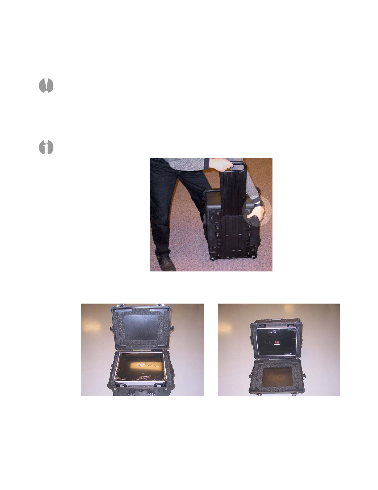
MaxPac 8230 XRA2/3-Series systems are always shipped in an associated Pelican case. Depending
on the configuration of your system – two or three screens and up to four disk drives – the
Pelican/MaxPac combination may weigh between 84 lbs and 99 lbs (including the packaging). If you
are unable to lift this weight safely, you should obtain assistance in unpacking and moving the system.
1) Place the cardboard packing box containing the Pelican case and MaxPac system on the floor.
Remove the packing slip from the outside of the box and save it for later use as discussed below.
2) Clear an area on a desk or table on which to place the MaxPac system.
Note: In order to raise or lower the handle on the Pelican case, use your thumb to slide the release
catch to the right (if looking toward the back of the case as shown in Figure 1-1).
Figure 1-1. Use the release catch to operate the handle on the Pelican case
3) Place the Pelican case flat on its back on the floor and open it (Figure 1-2).
Figure 1-2
Figure 1-2. Open the Pelican case containing the MaxPac System
4) With the aid of a colleague, carefully tip the case such that its lid is on the floor as shown in
Figure 1-3 (note that the case was rotated 180
tipped for the purposes of these photographs).
o
from the view shown in Figure 1-2 prior to it being
Figure 1-3
Page 10

4 MaxPac Dual/Triple-Screen 8230 XRA2/3-Series User Operation and Maintenance Guide
5) Have two people (one on each side) carefully slide the MaxPac out of the case (Figure 1-4).
Note: This process can be GREATLY facilitated by taking hold of the handle on top of the Pelican
case and tilting the case forward towards the lid resting on the floor. This will cause the MaxPac
to gently slide out of the case.
Figure 1-4
6) Slide the MaxPac all the way out until it is resting on the lid of the Pelican case (Figure 1-5).
7) Have two people (one on each side) lift the MaxPac system. Keeping your back straight, bending
at the knees and using your legs as much as possible, take the system out of the box and place it
on the cleared area noted in point (2) above.
Check the Packing List and Confirm Documentation
1) Carefully open the accessory box (delivered as a separate item) containing the keyboard, mouse,
power cord, MaxVision's extreme "Baghdad Filters", documentation packet, and any specialorder cabling or other items.
2) Check the packing slip to ensure that everything is as you expect with regard to the main system
and the contents of the accessory box. Pay particular attention to any special options you may
have requested, such as memory upgrades or specific graphics or sound subsystems.
3) Check the contents of the envelope containing the documentation associated with your system. In
addition to this manual along with any user guides and manuals associated with special upgrade
options you may have ordered (such as graphics cards), a basic MacPac 8230 XRA2/3-Series
documentation pack will include:
Windows® XP license and CD-ROM.
Motherboard manual.
Recovery CD (see also Appendix A).
Figure 1-5
Setting-Up Your MaxPac
Location
Your MaxPac 8230 XRA2/3-Series system needs to be positioned in a location with the capacity to
safely support at least 62 lbs to 76 lbs depending on its configuration. The unit should be
unobstructed so as to permit the free flow of cooling air through the intake fans at the sides of the
unit and exhaust air from the vents at the front of the unit.
Page 11
MaxPac Dual/Triple-Screen 8230 XRA2/3-Series User Operation and Maintenance Guide 5
Power Requirements
MaxPac 8230 XRA2/3-Series power supplies are auto-sensing 100 to 240 VAC, 50 to 60Hz units.
Ensure that the supplied power is sufficient, stable, and without spikes or surges for operation of your
MaxPac and other required equipment.
Attaching the Filters
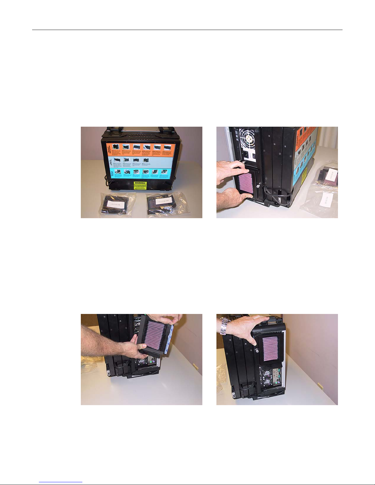
1) Stand the MaxPac system upright on the table; also, remove the two "Baghdad Filters" from the
accessory box (Figure 1-6).
Figure 1-6
2) The rear portion of the filter assembly is already attached to the main chassis. Present the front
portion of the left-hand filter assembly (including its filter element) to the rear portion of the
assembly on the main chassis. Use the flanges to engage the left-hand side of the assembly as
shown in Figure 1-7, and then engage the Velcro on the right-hand side of the assembly to its
counterpart on the main chassis.
3) Similarly, present the right-hand filter assembly and filter element to the rear portion of the
assembly, which is already attached to the main chassis. Use the flanges to engage the righthand side of the assembly as shown in Figures 1-8 and 1-9, and then engage the Velcro on the
left-hand side of the assembly to its counterpart on the main chassis.
Figure 1-7
Figure 1-8
Figure 1-9
Page 12
6 MaxPac Dual/Triple-Screen 8230 XRA2/3-Series User Operation and Maintenance Guide
Opening the Screens (Dual-Screen System)
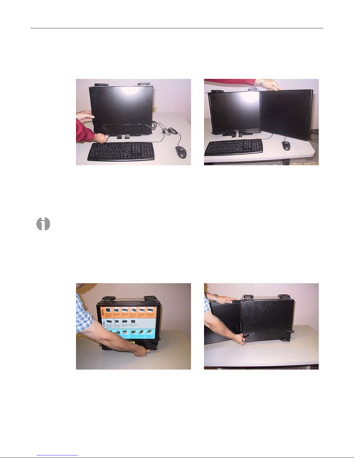
1) If you have a dual-screen system, press down on the release catch located at the lower left-hand
side of the system (Figure 1-10).
Figure 1-10
2) While continuing to press down on the release catch, pull the second screen away from the
system; unfold this second screen completely as shown in Figure 1-11.
Note: You may hear a squeaking noise when you unfold the second screen. This is caused by
the polyurethane clutch and is part of the friction mechanism that holds the screen steady. Do
NOT apply any lubricants to this mechanism, because they may degrade the polyurethane.
Opening the Screens (Triple-Screen System)
1) If you have a triple-screen system, press down on the release catch located at the lower righthand side of the system (Figure 1-12).
2) While continuing to press down on the release catch, pull the left-hand screen away from the
system until it is completely unfolded (Figure 1-13).
Figure 1-11
Figure 1-12
Figure 1-13
Page 13
MaxPac Dual/Triple-Screen 8230 XRA2/3-Series User Operation and Maintenance Guide 7
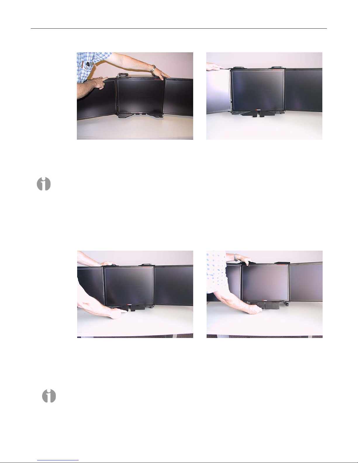
3) Now pull the left-hand edge of the right-hand screen away from the system (Figure 1-14).
Continue to pull this screen until it is completely unfolded (Figure 1-15).
Note: You may hear a squeaking noise when you unfold the second and third screens. This is caused by
the polyurethane clutches and is part of the friction mechanism that holds the screens steady. Do NOT
apply any lubricants to these mechanisms, because they may degrade the polyurethane.
Tilting the System
1) Place one hand underneath the system and the other hand on top of the system (Figure 1-16).
Press down lightly with the hand on top of the system while gently pulling the bottom of the
system forward with your other hand.
Figure 1-14
Figure 1-15
Figure 1-16
2) Tilt the system back. While holding the top of the system with one hand, reach under the system
with the other hand, grasp the bases of the two integrated support stands, squeeze the bases
together, and pull the support stands down (Figure 1-17).
Note: The stands are spring-loaded and will expand outward when you release them. The
support stands can be set to various positions depending on the required viewing angle of the
system/screens (the most extreme extended position is generally used only for maintenance
purposes).
Figure 1-17
Page 14
8 MaxPac Dual/Triple-Screen 8230 XRA2/3-Series User Operation and Maintenance Guide
Accessing and Connecting the Keyboard, Mouse, etc.
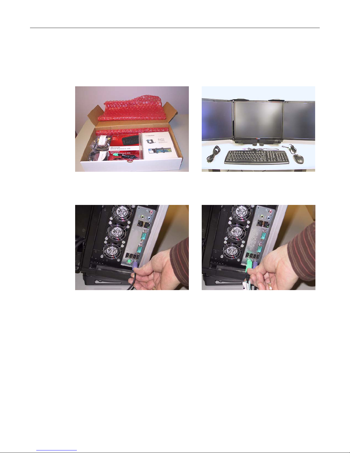
1) Return to the accessory box containing the keyboard, mouse, and power cord (Figure 1-18) and
place these items on the table in front of the system (Figure 1-19)
Figure 1-18
2) Plug the keyboard into the PS2 connector in the lower right-hand corner of the main interface
panel, which is on the right-hand side of the system (Figure 1-20).
Figure 1-20
3) The mouse may be plugged into the PS2 connector located next to the keyboard connector as
shown in Figure 1-21. Alternatively, you may remove the green USB-to-PS2 connector from the
end of the mouse cable and then plug the mouse into one of the USB ports located just above the
two PS2 ports.
Figure 1-19
Figure 1-21
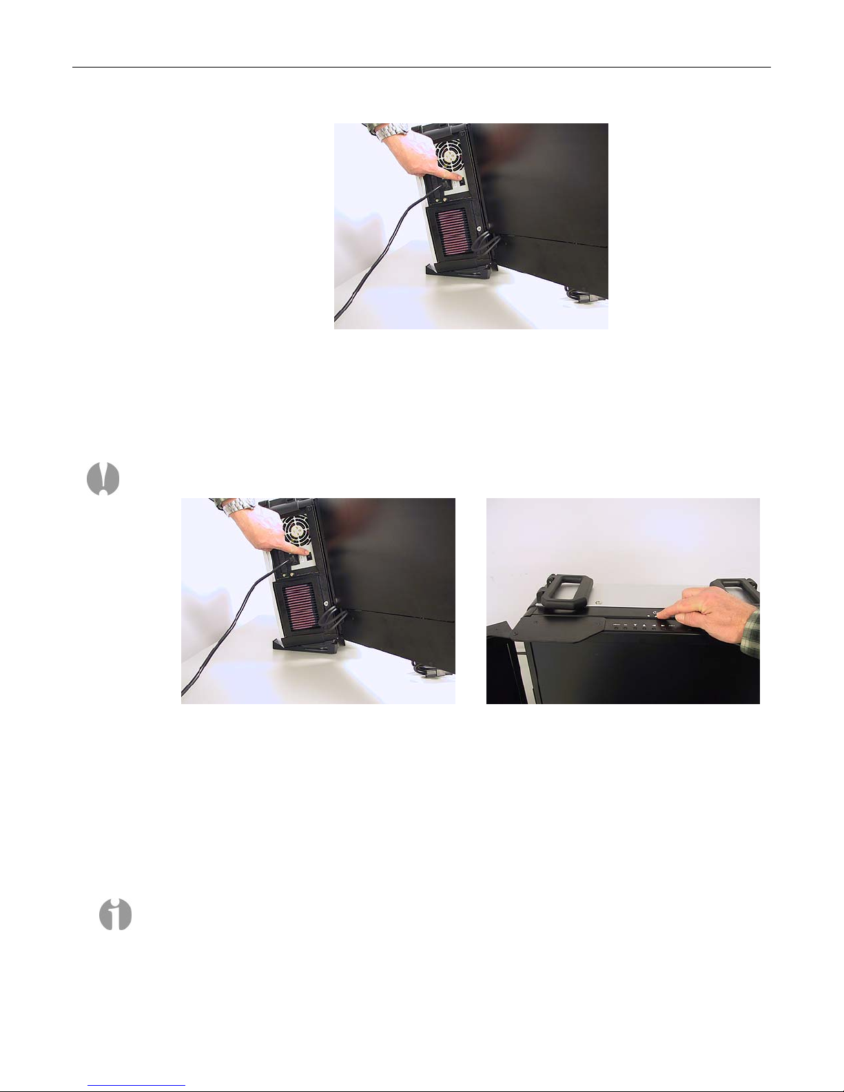
4) Plug the power cord into the main power input port, which is located on the left-hand side of the
system, and then plug the other end of the cable into a suitable power outlet. Observe the main
(hard) power switch located to the right of the power input port (Figure 1-22).
Page 15
MaxPac Dual/Triple-Screen 8230 XRA2/3-Series User Operation and Maintenance Guide 9
Figure 1-22
Powering-Up Your MaxPac
1) Ensure that the main (hard) power switch – the switch located just to the right of the main power
input connector – is in its ON position (Figure 1-23).
Note: When the unit is being moved or serviced, you should ensure that the main power switch
is in its OFF position.
Figure 1-23
2) Press and release the soft power switch located at the top of the system immediately behind the
center display screen (Figure 1-24)
3) Due to extensive system initialization and verification checks, the BIOS boot-up process can take
a significant amount of time, especially in the case of systems with large amounts of memory. In
the case of a system containing 8 GB of RAM, for example, it can take 45 seconds before all
three LEDs above the numerical keypad on the keyboard flash to indicate that the system is at a
point where information should start to appear on the main display.
Figure 1-24
Note: Even if nothing appears on the main display, the fact that the three LEDs flash on the
keyboard indicate that the system is alive.
Page 16

10 MaxPac Dual/Triple-Screen 8230 XRA2/3-Series User Operation and Maintenance Guide
Logging On for the First Time
1) Following the initial BIOS boot-up sequence, you will be presented with the Windows XP
Professional Startup screen:
2) After a few seconds – and assuming this is the first time you have powered-up your system –
you will be presented with the Windows XP Professional Setup Wizard dialog. Follow the
on-screen instructions provided by the setup wizard; these will include:
• Accepting the license agreement.
• Confirming (or modifying) the region and/or language settings.
• Entering your company name and organization name.
• Entering the product key (that is, the OS license number). This license number will be found
on the OS license sticker attached to your machine. This sticker will be located on the base of
the machine (in this context, the term "base" refers to the bottom of the system when it is
standing on the table as illustrated earlier in this manual).
• Entering the name you wish to be associated with this system. Assuming that you intend to
connect your system to a network, this is the name that will appear on the network, and thus
it must be unique to your network (you may wish to obtain this name from your network
administrator).
• Entering a password for the system and confirming it.
• Specifying the date and time zone settings associated with your system’s location.
• Specifying your network settings (it is strongly recommended that you select the default
Typical option, otherwise you should leave this step to your network administrator).
• Entering the names of your workgroup and computer/network domains (ask your network
administrator to provide you with these details).
3) Once you have completed all of the steps presented by the setup wizard, click the Finish button,
which will cause the system to automatically reboot itself.
Page 17
MaxPac Dual/Triple-Screen 8230 XRA2/3-Series User Operation and Maintenance Guide 11
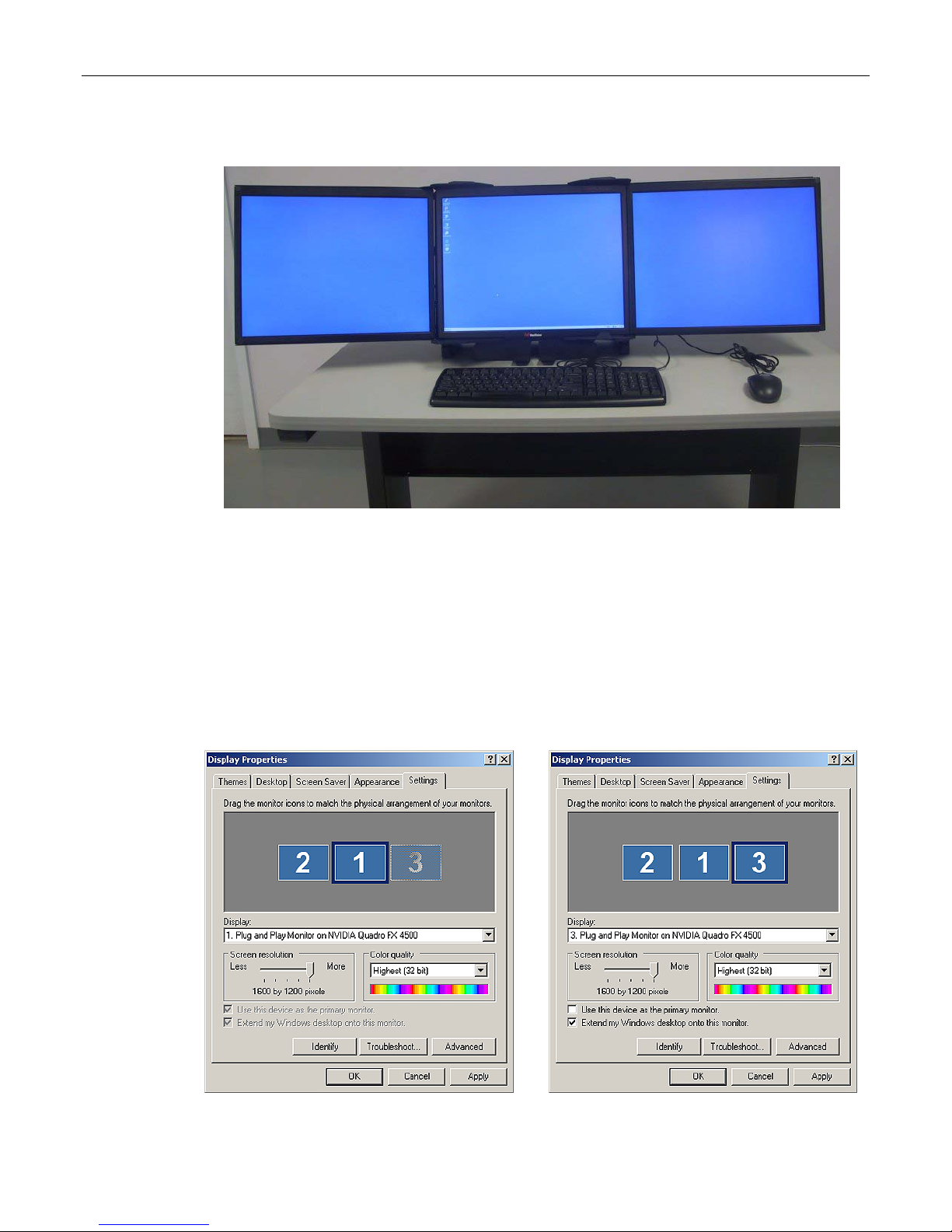
4) Observe the default MaxVision desktop appear on the screen:
5) Note that, upon this first reboot, all three screens may not initially be active (although the screen
drivers are loaded for both graphics boards, in rare cases they may not be enabled and/or
properly configured). Alternatively, the screens may all be active, but they may be improperly
ordered such that the mouse cursor leaps from screen to screen in a non-intuitive way.
In such a case, right-mouse-click on a blank area of an active screen/desktop, select the
Properties item from the resulting pop-up menu, then select the Settings tab, and then set up
the three screens as shown in Figures 1-25 and 1-26.
If the ordering of the screens is not as shown below, simply drag the screen icons into the correct
position. Ensure that the center screen (number '1') is set to be the primary display. When you've
finished making chances, click the Apply button.
Figure 1-25
Figure 1-26
Page 18

12 MaxPac Dual/Triple-Screen 8230 XRA2/3-Series User Operation and Maintenance Guide
Registering/Activating Your OS
1) At some stage after you’ve powered up your system for the first time as discussed in the previous
section, a small “xx days left for activation” pop-up will appear in the lower right-hand corner of
the screen:
2) Clicking on the “X” will dismiss this pop-up (it will return to bug you later). Alternatively, clicking
on the body of this pop-up will result in the “Let’s activate Windows” dialog appearing on your
screen.
3) Select one of the three options (Activate over the internet, Activate by phone, or Remind me
later), then click the Next button and follow the on-screen directions.
Note: It is recommended that you register and activate your OS as soon as possible. After the 30
day grace period has expired, the system won’t even let you logon until you do register and
activate the OS.
Shutting Down the System
In order to shut the system down gracefully you must perform the following steps:
1) Close down any applications that are currently running.
2) Use the Start > Shut Down command.
3) Select one of the following options in the pull-down menu:
• Restart Shutdown and restart the system.
• Shutdown Shutdown the system.
• Log Off Log off the current user session.
4) Click the OK button.
“Dos and Don’ts”
1) Always disconnect the external AC power source when removing or installing system components
(and always turn the main power switch to its OFF position when you disconnect AC power).
2) In the case of extreme dust conditions, it is imperative that you use (and maintain) the oil-based
"Baghdad Filters" supplied with your system (see also the discussions on maintaining these filters
as presented later in this manual).
Page 19

MaxPac Dual/Triple-Screen 8230 XRA2/3-Series User Operation and Maintenance Guide 13
Chapter 2: Setting-Up the
Software/Devices/Network/RAID Array
Page 20
14 MaxPac Dual/Triple-Screen 8230 XRA2/3-Series User Operation and Maintenance Guide
Setting-Up the Network
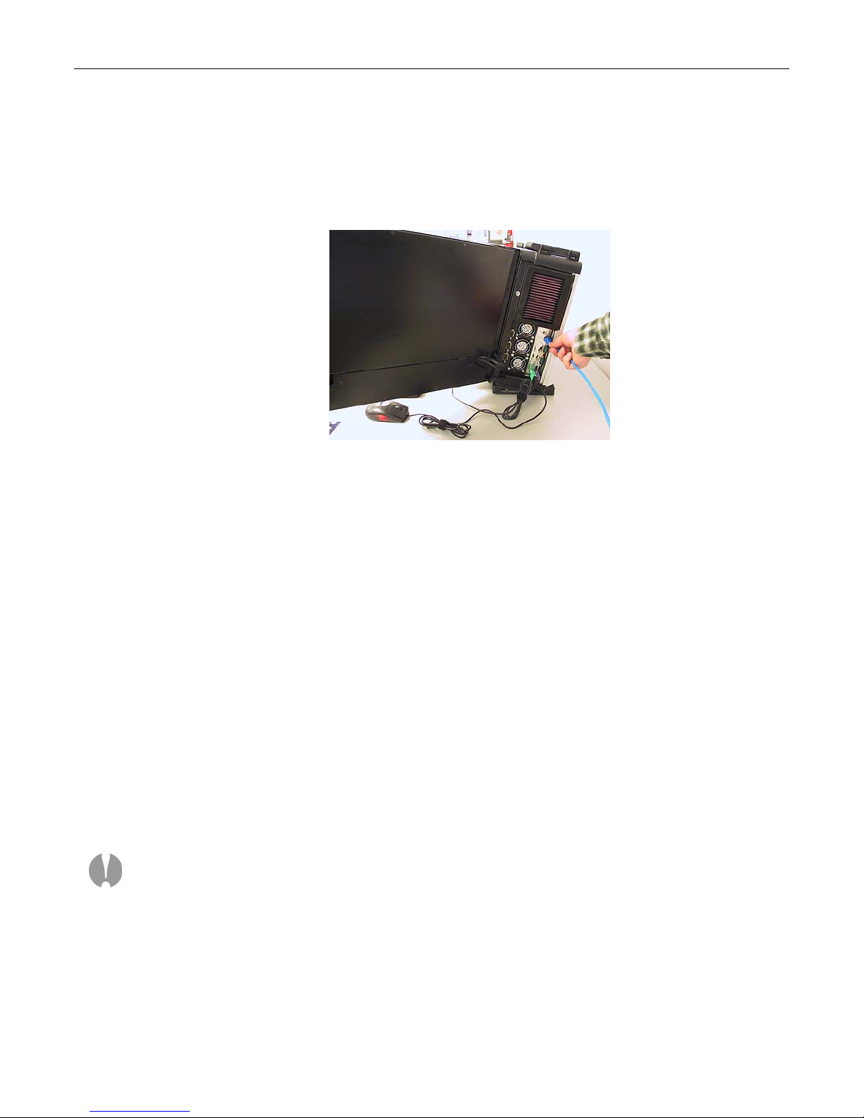
In the majority of environments, it is sufficient to use the Windows XP defaults for the network. Simply
connect the network cable (Figure 2-1) and the system should auto-detect the presence of the
network and the data/communications light next to the network cable connector should start to flash.
Figure 2-1. Connecting the network cable
The easiest way to test your network connection is to invoke your web browser and visit a website
such as www.MaxVision.com. In the event of any problems or special requirements, you should first
consult your on-site IT representative (if the problems persist, contact MaxVision support as
discussed in Appendix D).
Setting-Up the Graphics
When you receive your MacPac dual/triple-screen X-Class system, you will find that the graphics
subsystem has been pre-installed with the following (recommended) characteristics:
• Color Quality: Highest (32-bit)
• Resolution: 2, or 3 x 20.1” displays: 1600 x 1200
Irrespective of the configuration, the graphics on your system will have been custom pre-configured to
suite your particular requirements.
MaxPac systems are available with a variety of different graphics cards depending on your unique
application. The standard configuration for a triple-screen system is to have the center and right-hand
displays controlled by a PCI Express-based NVIDIA Quadro FX4500. For the MaxPac 8230 series
the left-hand display and projector port are controlled by a second PCI Express-based NVIDIA
Quadro FX series board.
Note: OpenGL™ acceleration is now available on all displays controlled by PCI Express-based
NVIDIA Quadro FX series controllers. This allows the user to run applications requiring OpenGL
acceleration on all displays as long as all are controlled by the same NVIDIA Graphics driver.
If you do have a special graphics card, you may consult the manual associated with this card (this
manual will be included in your documentation package as discussed in Chapter 1) or contact
MaxVision support (as discussed in Appendix D) for more information.
Page 21
MaxPac Dual/Triple-Screen 8230 XRA2/3-Series User Operation and Maintenance Guide 15
Adjusting the Screens
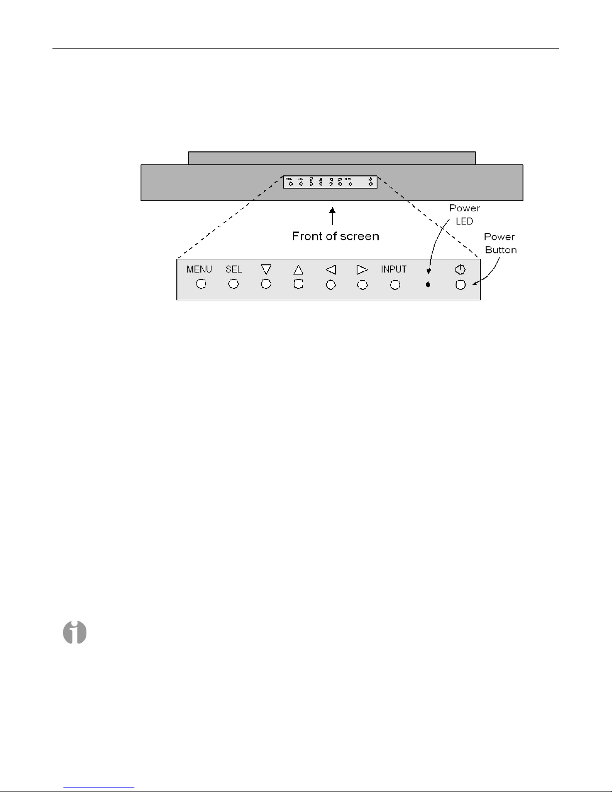
In the case of both dual- and triple-display configurations, each screen has a set of controls mounted
on the top of the display (Figure 2-2).
Figure 2-2. Top-down view of screen controls on dual- and triple-display systems
Observe the power button located to the right of the power light-emitting diode (LED). This is an
independent power button for the display/screen.
Pressing the MENU button will bring up a series of items on the screen. Use the up/down buttons to
move between these items; press and release the SEL button to select that item; and use the
right/left buttons to vary the settings.
Some custom configurations allow the display to be driven from multiple sources. In this case,
pressing the INPUT button selects between digital and analog inputs. These custom configurations
will come equipped with a special documentation addendum that details the actions of the INPUT
button; in the case of standard configurations, the source should always be set to “Digital.”
Setting Up Video Input for Picture-in-Picture
In the case of MaxPac 8230 XRA2 (dual-screen) systems, the right-hand monitor supports multiple
inputs: the default DVI-I input from the system and an external VGA input that can be used for
picture-in-picture monitoring purposes. In the case of MaxPac 8230 XRA3 (triple-screen) systems,
both the left- and right-hand monitors support this capability.
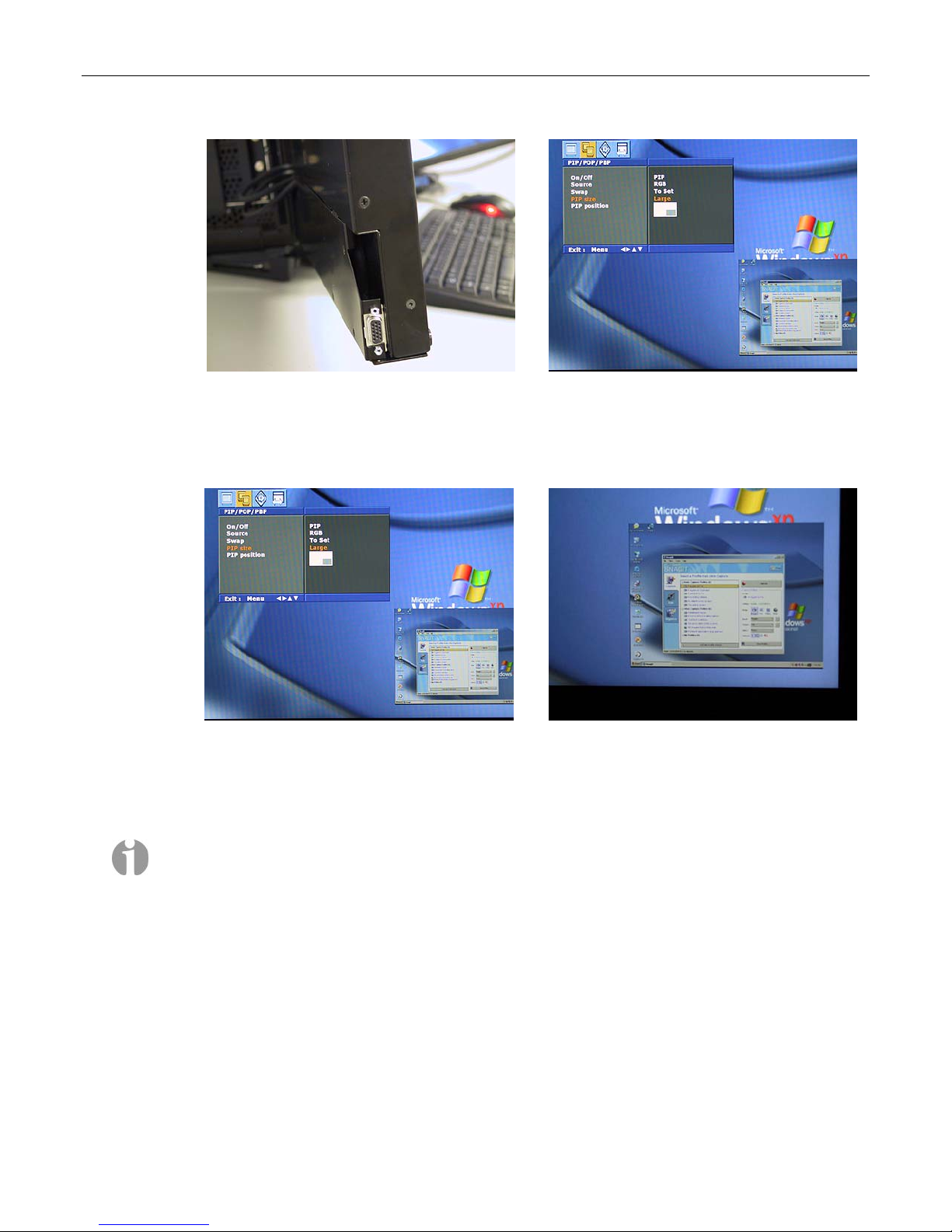
1) Observe the VGA connector associated with the left-hand screen (Figure 2-3). The external video
source would be fed into this connector as shown for the right-hand screen (Figure 2-4).
Note: For the purposes of this example, the video signal being used as input to the right-hand
screen originates from another PC. In reality, this input could come from any VGA video source
with a resolution no higher than 1024 x 768.
Page 22
16 MaxPac Dual/Triple-Screen 8230 XRA2/3-Series User Operation and Maintenance Guide
Figure 2-3
Figure 2-4
2) In order to access the external video source, press the Menu button in the controls mounted on
the top of that display (Figure 2-2),and then use the left/right arrow buttons on this control panel
to access the Picture-in-Picture dialog (Figure 2-5)
Figure 2-5
Figure 2-6
3) Use this dialog to turn the Picture-and-Picture window On/Off and to specify characteristics such
as the size and position of the Picture-and-Picture window (located in the lower right-hand corner
of the screen in Figures 2-5 and 2-6).
Note: The video source and the Picture-in-Picture window must be set to the same resolution,
which must be less-than or equal-to 1024 x 768.
Page 23
MaxPac Dual/Triple-Screen 8230 XRA2/3-Series User Operation and Maintenance Guide 17
Configuring the RAID Array (with Separate System Drive)
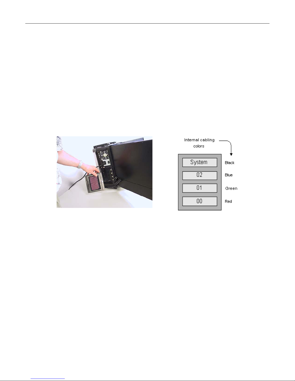
Note that these discussions reflect system configurations with a separate system drive as illustrated
in Figures 2-7 and 2-8). Configurations that have the system partition established on the RAID array
itself (leaving a hot-spare drive) are discussed later in this chapter.
When you take possession of your MaxPac 8230 XRA2/3, the RAID system will already have been
established, initialized, and verified. The instructions in this section are intended to address those rare
situations where you need to replace a degraded/failed drive or you wish to rebuild the RAID system
from the ground up.
Your MaxPac system can contain up to four SATA hot-swappable hard disk drives presented in a
4-drive disk caddy. This caddy is located on the lower left-hand side of the main chassis under the
"Baghdad Filter" assembly as shown in Figure 2-7 (the numbering of the disks is as shown in
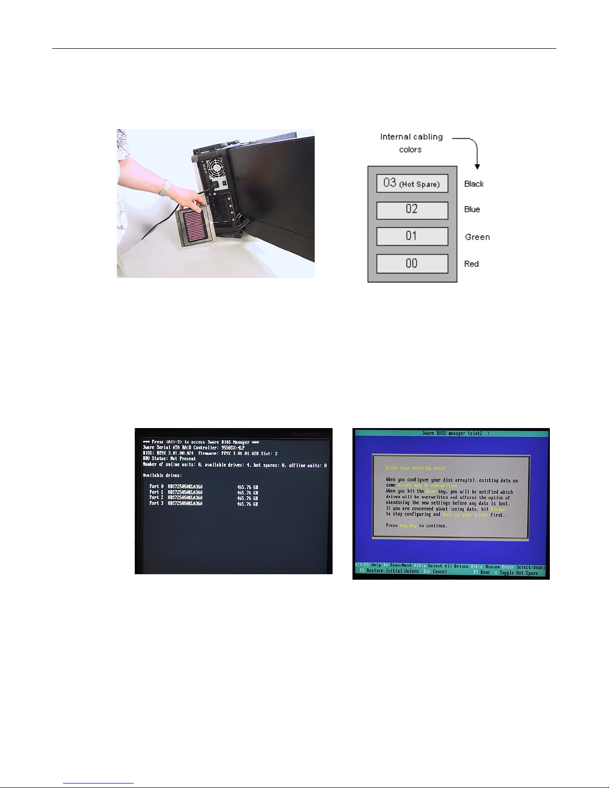
Figure 2-8). In the case of a typical RAID 5 system, the upper disk is the system disk, while the
lower three disks are used to implement the RAID data array.
Figure 2-7 Figure 2-8
Installing the Web-Based 3ware Software
If you reload your operating system, then you will also need to reload the appropriate RAID driver
followed by 3ware's 3DM 2 web-based RAID management application as follows:
1) Power-up the system. The operating system will see the RAID controller as a new device and will
therefore prompt you to load the appropriate driver from the 3ware CD, which is provided with
your system.
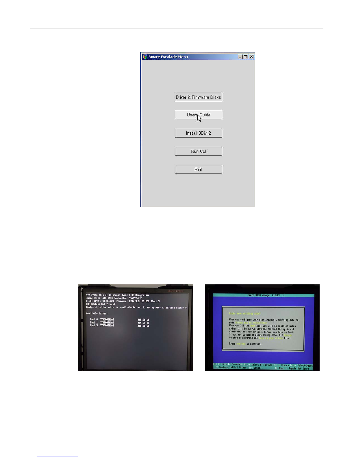
2) Insert the 3ware CD. The auto-play function will bring up the 3ware Escalade Menu as shown in
Figure 2-9. Initially you should ignore this menu; don’t dismiss it, but instead use the operating
system's Device Manager utility to look for the 3ware driver on the CD and install it.
3) Once the 3ware driver has been loaded, return to the 3ware Escalade Menu and click the Install
3DM 2 button.
4) Approve the license agreement in the ensuing pop-up dialog.
5) Following acceptance of the license agreement, you may be presented with the operating
system's standard Welcome to New Connection Wizard dialog. In this case, use this dialog to
setup your network connection.
6) Following this wizard, 3ware's 3DM 2 software will be installed (when prompted to do so, allow
the installation script to place a 3DM 2 icon on your desktop).
Page 24
18 MaxPac Dual/Triple-Screen 8230 XRA2/3-Series User Operation and Maintenance Guide
Figure 2-9
Building a New 3ware RAID 5 Array from Scratch
The discussions in this section assume that you have an existing system disk and – for one reason or
another – have installed three new/empty data disks.
1) Start to power-up the system. When you see the BIOS message "<Alt-3> to access 3ware BIOS
Manager" (Figure 2-10) press and hold the <ALT> (alternate) key and – while still holding this key
– press the number "3" key. This will invoke the 3ware BIOS manager; in most cases, you will be
presented with a warning screen as shown in Figure 2-11.
Figure 2-10
Figure 2-11
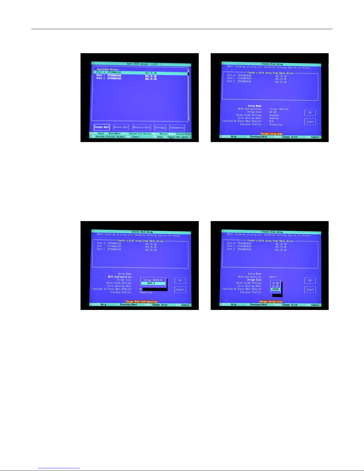
2) Press any key to continue, which will take you fully into the 3ware BIOS Manager. Observe that
the Create Unit option is selected by default. Use <Alt-A> to select all of the drives; asterisk "*"
characters appear to the left of each drive's port number to indicate that the drive has indeed
been selected (Figure 2-12)
Page 25
MaxPac Dual/Triple-Screen 8230 XRA2/3-Series User Operation and Maintenance Guide 19
Figure 2-12
Figure 2-13
3) Ensure that the Create Unit item is still selected (the white box shown to the bottom left of the
screen in Figure 2-12), and then press the <Enter> key to invoke the Create Disk Array screen
(Figure 2-13).
4) Use the up/down arrow keys to highlight the RAID Configuration item, and then press the
<Enter> key to access an associated pop-up dialog (Figure 2-14).
5) Use the up/down arrow keys to highlight the RAID 5 option, and then press the <Enter> key to
select this option.
Figure 2-14
Figure 2-15
6) Use the up/down arrow keys to highlight the Stripe Size item, and then press the <Enter> key to
access an associated pop-up dialog (Figure 2-15).
7) Use the up/down arrow keys to highlight the 256 KB option, and then press the <Enter> key to
select this option.
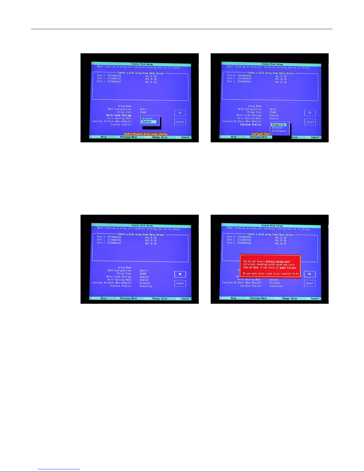
8) Use the up/down arrow keys to highlight the Write Cache Setting item, and then press the
<Enter> key to access an associated pop-up dialog (Figure 2-16).
9) Use the up/down arrow keys to highlight the Enabled option, and then press the <Enter> key to
select this option.
Page 26
20 MaxPac Dual/Triple-Screen 8230 XRA2/3-Series User Operation and Maintenance Guide
Figure 2-16
Figure 2-17
10) Use the up/down arrow keys to highlight the StorSave Profile item, and then press the <Enter>
key to access an associated pop-up dialog (Figure 2-17).
11) Use the up/down arrow keys to highlight the Protection option, and then press the <Enter> key
to select this option.
12) Use the up/down/right/left arrow keys to highlight the OK item (Figure 2-18) and then press the
<Enter> key to save your changes.
Figure 2-18
Figure 2-19
13) You will be presented with a warning dialog as shown in Figure 2-19. Press the Y (yes) to allow
the write cache to be enabled (note that this mode significantly improves performance, but it can
result in a loss of data in the event of a power failure, so MaxVision STRONGLY recommends the
use of an uninterruptible power supply (UPS) with your system).
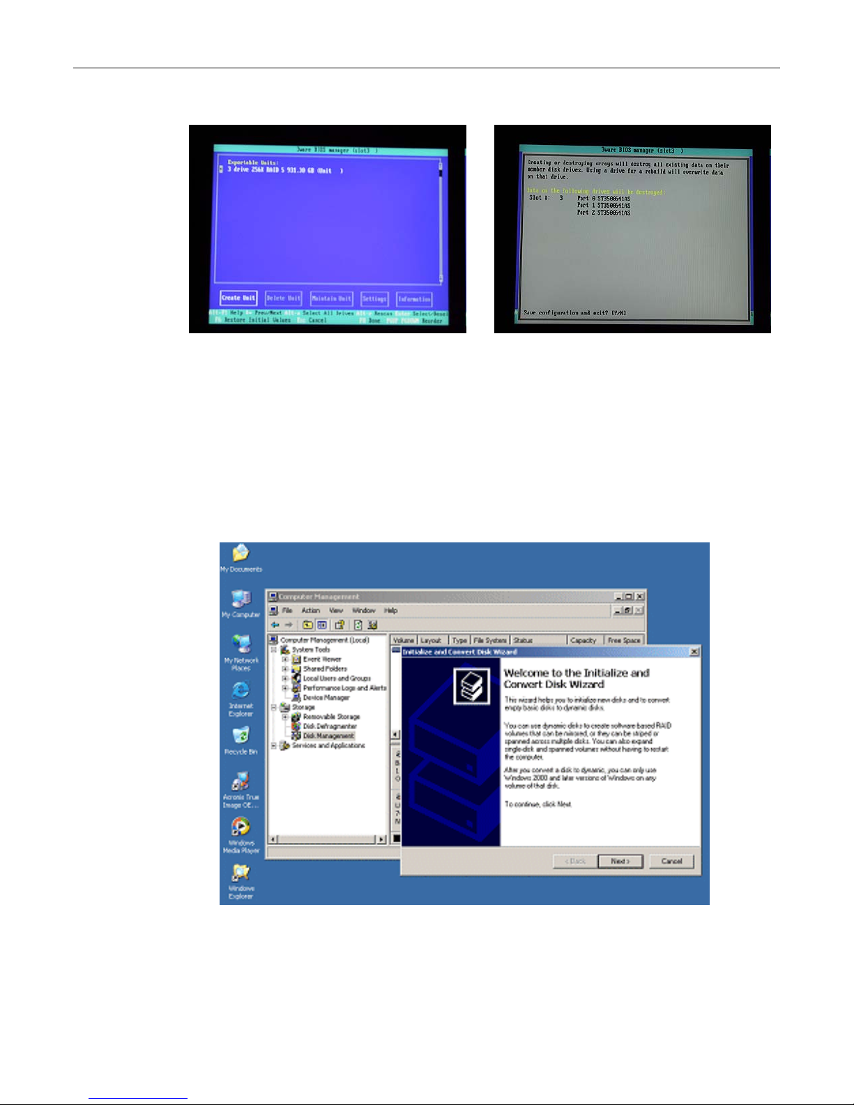
14) At this point, you will be presented with a summary description of the RAID array you have
defined (Figure 2-20).
15) Press the <F8> key to request that your array be established and to exit the 3ware BIOS
setup utility.
Page 27
MaxPac Dual/Triple-Screen 8230 XRA2/3-Series User Operation and Maintenance Guide 21
Figure 2-20
Figure 2-21
16) You will be presented with a warning screen as shown in Figure 2-21. Press the Y (yes) key in
order to establish your array and exit the 3ware BIOS setup utility. The system will automatically
reboot itself in order to make your new RAID array available to the operating system. During the
boot process you will see the BIOS report the existence of your new RAID array.
17) Once the system has booted up into Windows®, right-click on the My Computer icon and then
select the Manage option. In the ensuing Computer Management dialog, click on the Disk
Management item. As you have just created a new RAID array, this will automatically launch the
Initialize and Convert Disk Wizard as shown in Figure 2-22.
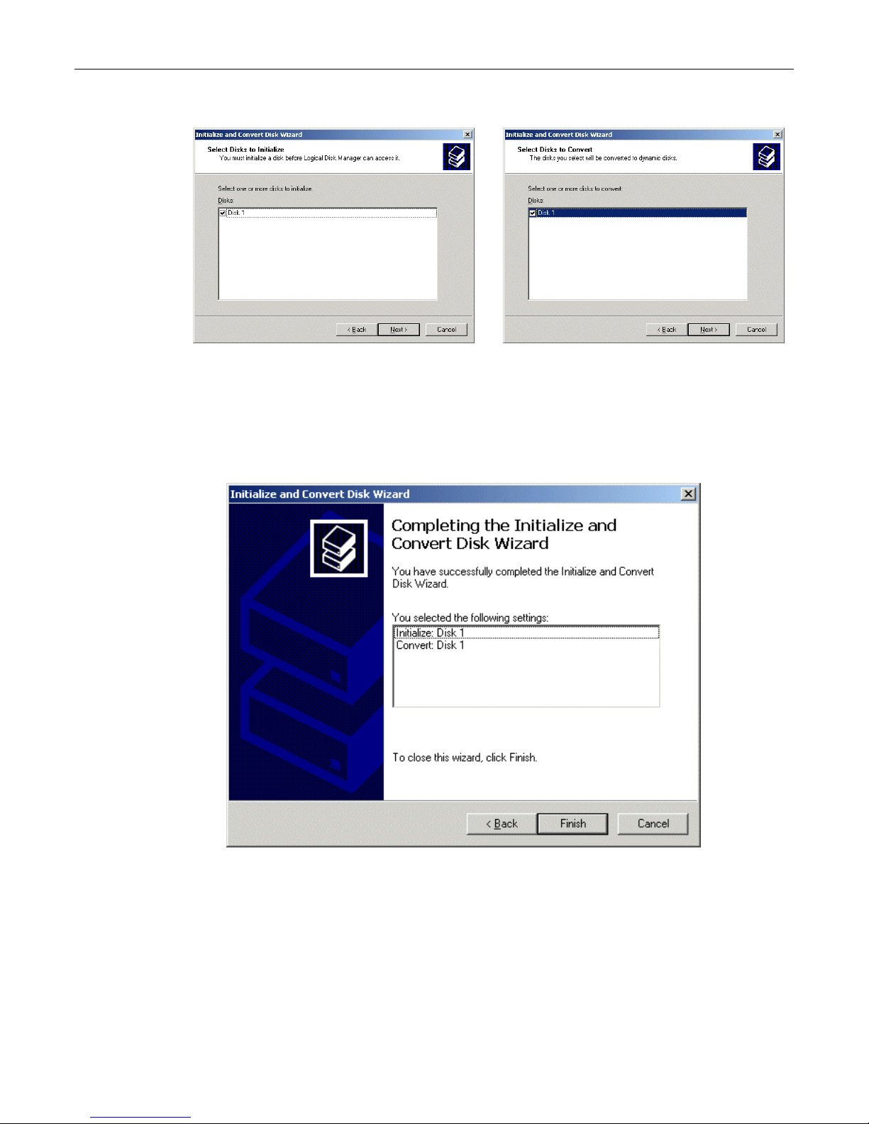
18) Click the Next button to be presented with the Select Disk to Initialize screen. Click the Disk 1
item as shown in Figure 2-23.
Figure 2-22. The Initialize and Convert Disk Wizard
Page 28
22 MaxPac Dual/Triple-Screen 8230 XRA2/3-Series User Operation and Maintenance Guide
Figure 2-23
Figure 2-24
19) Click the Next button to be presented with the Select Disk to Convert screen. Click the Disk 1
item as shown in Figure 2-24.
20) Click the Next button to be presented with the Completing the Wizard screen as shown in
Figure 2-25, and then click the Finish button to perform the operations and exit the wizard.
21) Observe that the Disk Management area of the Computer Management dialog now shows Disk 1
as being a Dynamic disk that is – as yet – unallocated as shown in Figure 2-26.
Figure 2-25. The Completing the Wizard dialog
Page 29

MaxPac Dual/Triple-Screen 8230 XRA2/3-Series User Operation and Maintenance Guide 23
Figure 2-26. Disk 1 is – as yet - unallocated
Note: In the case of the system used in this example, the system disk was 120 GB in size, while the
three data disks used to form the RAID array were each 400 GB in size.
Observe in Figure 2-26 that Disk 1 is shown as being approximately 800 GB in size, where 800 GB
equates to 2/3 of the 3 x 400 GB capacity of the data disks (the remaining 400 GB is used to provide
the RAID 5 redundancy).
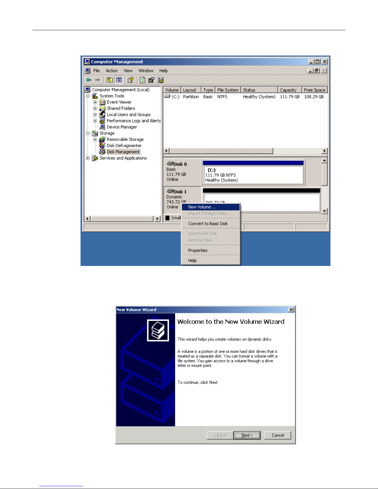
22) Now, right-click on the Disk 1 item in the lower-right-hand portion of the screen, and then select
the New Volume option from the ensuing pop-up menu as shown in Figure 2-27.
Page 30
24 MaxPac Dual/Triple-Screen 8230 XRA2/3-Series User Operation and Maintenance Guide
Figure 2-27. Select the New Volume option
23) Observe the New Volume Wizard appear as shown in Figure 2-28.
Figure 2-28. The New Volume Wizard
Page 31
MaxPac Dual/Triple-Screen 8230 XRA2/3-Series User Operation and Maintenance Guide 25
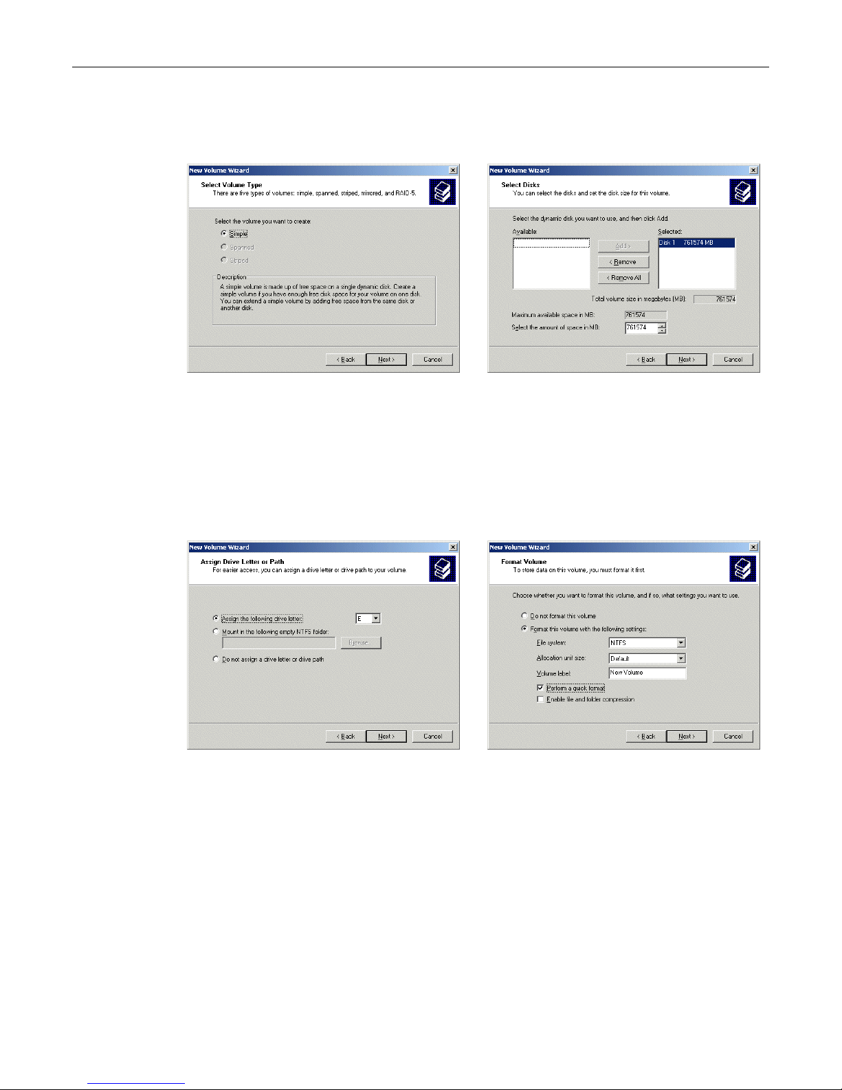
24) Click the Next button to be presented with the Select Volume Type screen. Click the Simple
option as shown in Figure 2-29.
Figure 2-29
Figure 2-30
25) Click the Next button to be presented with the Select Disk screen. Ensure that the Disk 1
item is selected and appears in the Selected column on the right-hand side of the dialog as
shown in Figure 2-30.
26) Click the Next button to be presented with the Assign Drive Letter or Path screen. Ensure
that the Assign the Following Drive Letter item is selected and accept the default letter
presented by the system (or enter a different letter if you require) as shown in Figure 2-31.
Figure 2-31
Figure 2-32
27) Click the Next button to be presented with the Format Volume screen. Click the Format this
volume with the following settings item as shown in Figure 2-32. Ensure that the settings
are File system = NTFS, Allocation unit size = Default, and Volume Label = user defined
(the default is "New Volume"). Also ensure that the Perform a quick format item is selected.
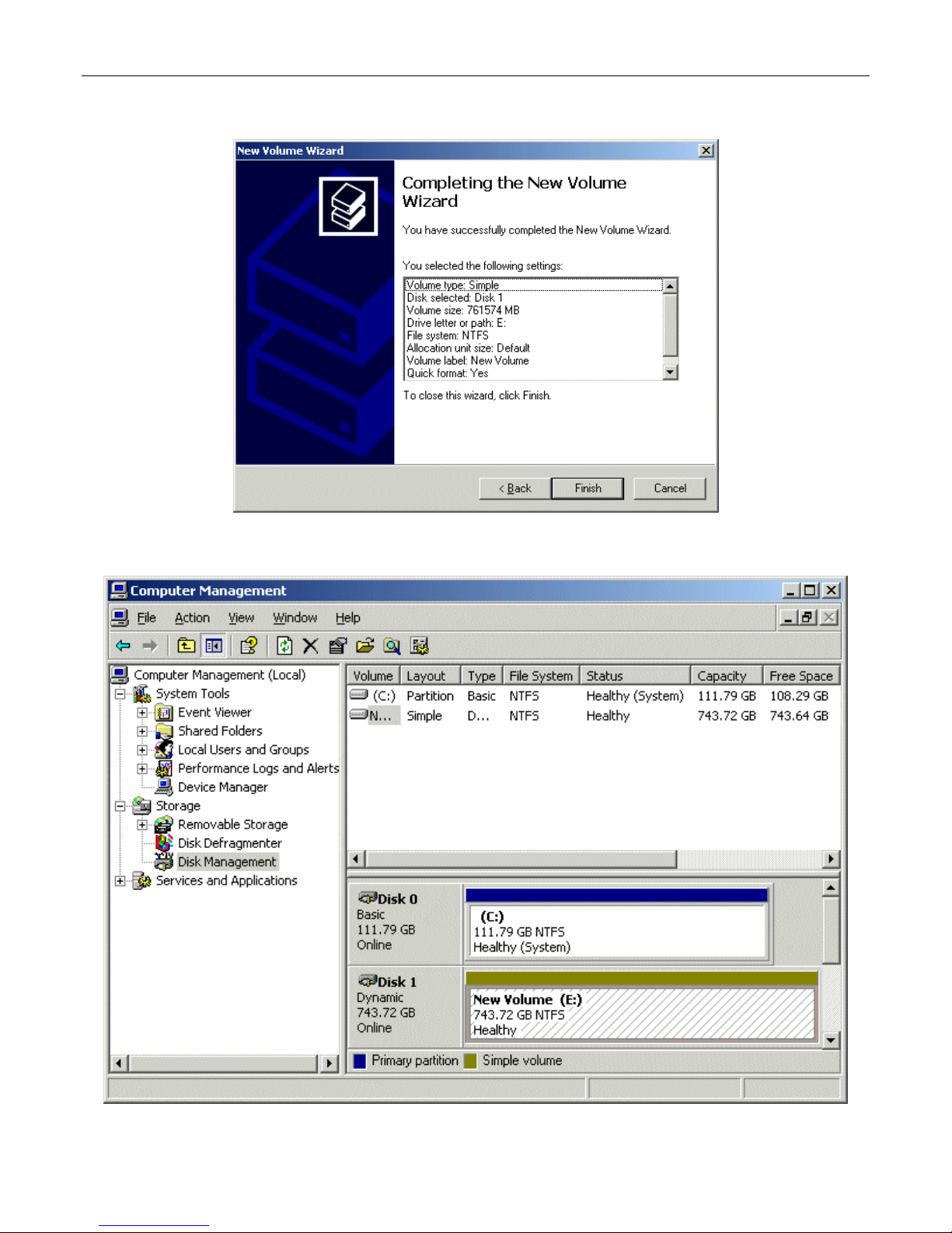
28) Click the Next button to be presented with the Completing the New Volume Wizard screen
as shown in Figure 2-33.
29) Click the Finish button to perform all of the operations and exit the wizard.
30) Observe that the Disk Management area of the Computer Management dialog now
shows Disk 1 as being Dynamic, Online, and Healthy as illustrated in Figure 2-34.
Page 32
26 MaxPac Dual/Triple-Screen 8230 XRA2/3-Series User Operation and Maintenance Guide
Figure 2-33. The Completing the Wizard dialog
Figure 2-34. Disk 1 is now shown as being Dynamic, Online, and Healthy
Page 33
MaxPac Dual/Triple-Screen 8230 XRA2/3-Series User Operation and Maintenance Guide 27
Rebuilding an Existing (Failed) 3ware RAID 5 Array
The discussions in this section assume that you originally have a good, working RAID 5 array. In this
case, if you double-click the Connect to 3DM 2 icon on your desktop and login to the ensuing
webpage using the default password (which is 3ware), you will see that the status of your array looks
something like that shown in Figure 2-35.
Figure 2-35
Once you have observed this good array, exit out of the 3DM 2 web interface. At some stage, one of
the disks in the array may start to degrade or go completely off-line. For the purposes of these
discussions, we are going to power down the system, physically remove Disk 01 from the array
(thereby simulating a catastrophic failure on this disk) and power up the system back up again.
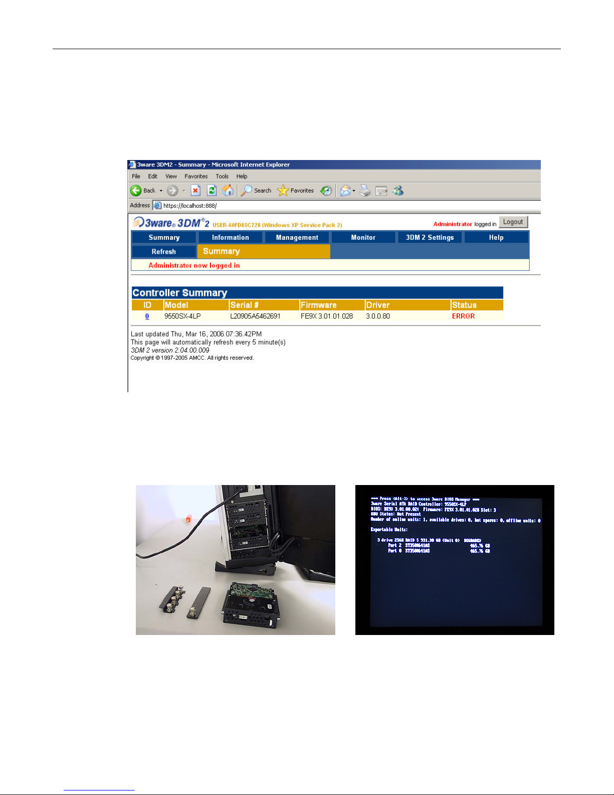
1) Power down the system and remove the center data disk (Disk 01) as shown in Figure 2-36.
Figure 2-36
Figure 2-37
2) Power the system back up again. The BIOS detects the fact that there is a problem with the RAID
array and displays an appropriate message (Figure 2-37). Press the <Pause Break> key to freeze
the display; from this (and Figure 2-8) you will be able to determine which drive has failed.
3) Press and hold the soft power key in order to power the system down.
Page 34
28 MaxPac Dual/Triple-Screen 8230 XRA2/3-Series User Operation and Maintenance Guide
4) Remove the failed drive and replace it with a good drive of the same type and capacity
(remember that we only removed the drive above in order to simulate a catastrophic failure
scenario).
5) Power the system up again all the way into windows.
6) Double-click the Connect to 3DM 2 icon on your desktop and login to the ensuing webpage
using your administrator password (note that you may need to contact your IT department in
order to obtain this password).
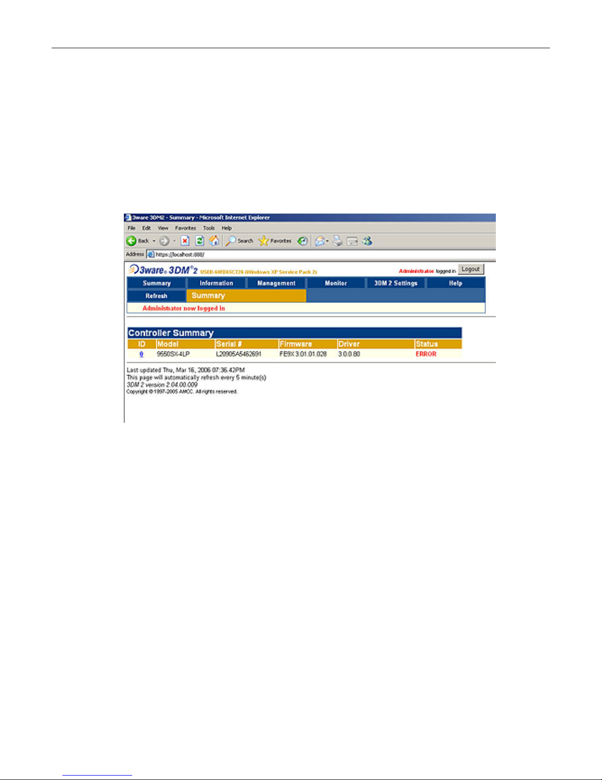
7) After you have logged in as the administrator, you will see a status of ERROR in the 3DM 2
interface (Figure 2-38).
Figure 2-38.
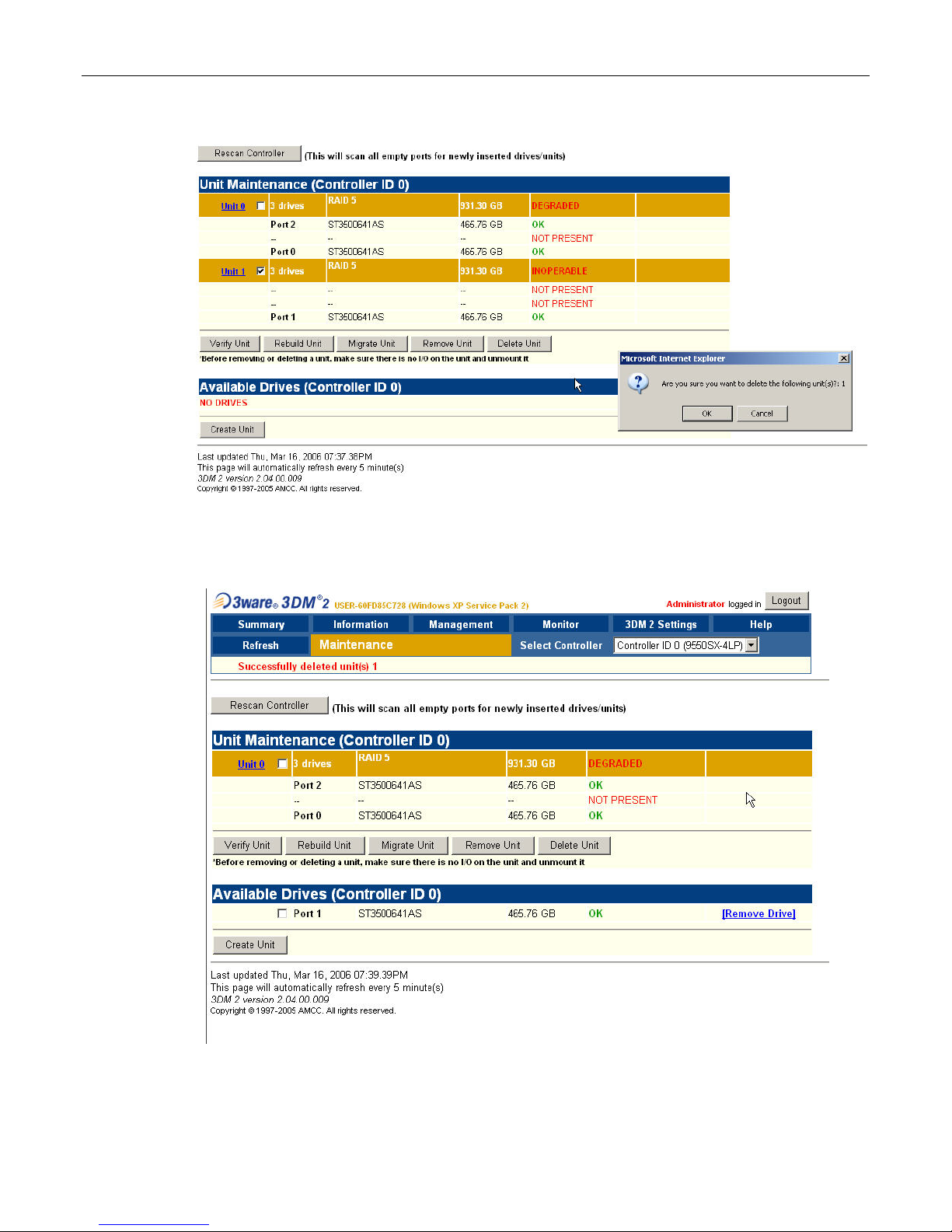
8) Observe that the system reports the two good drives as being in a DEGRADED unit as shown
in Figure 2-39.
9) Depending on the past history of the disk (whether or not it was previously part of a 3ware RAID
array) the system may report that the new disk is INOPERABLE as illustrated in Figure 2-39.
Alternatively, the system may report the new disk as being AVAILABLE as illustrated in Figure 2-40.
Assuming that the new disk is reported as being INOPERABLE, click the checkbox associated with
that unit (Unit 1 in this example) and then click the Delete Unit button. Observe that the system will
present you with a confirmation dialog as shown in Figure 3-39. Click the OK button, and observe
that the new disk is now reported as being AVAILABLE as illustrated in Figure 2-40.
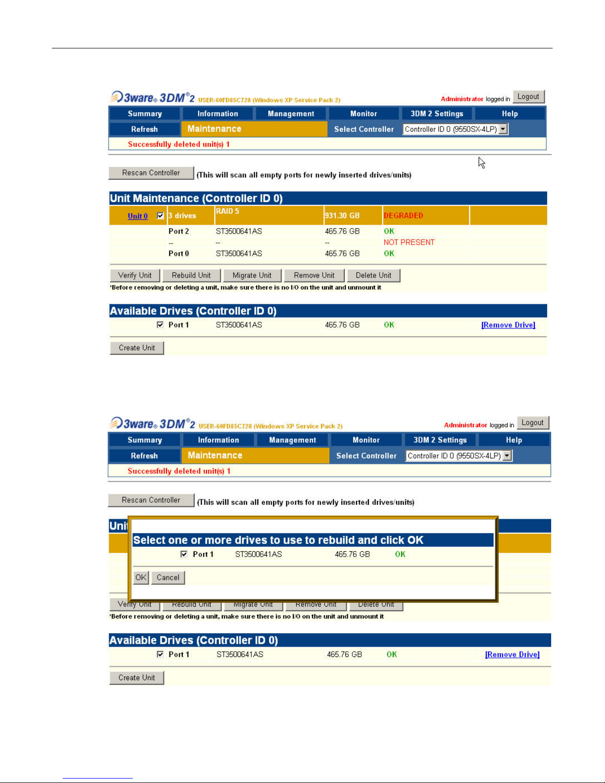
10) Click the checkbox associated with the two good drives (shown as Unit 0 in this example) and also
click the checkbox associated the new replacement drive (shown as Port 1 in this example) and
then click the Rebuild Unit button associated with the two good drives as illustrated in Figure 2-41.
11) Observe the ensuing pop-up dialog box as shown in Figure 2-42. Click the checkbox associated
with the new drive, and then click the OK button.
Page 35
MaxPac Dual/Triple-Screen 8230 XRA2/3-Series User Operation and Maintenance Guide 29
Figure 2-39.
Figure 2-40.
Page 36
30 MaxPac Dual/Triple-Screen 8230 XRA2/3-Series User Operation and Maintenance Guide
Figure 2-41.
Figure 2-42.
Page 37
MaxPac Dual/Triple-Screen 8230 XRA2/3-Series User Operation and Maintenance Guide 31
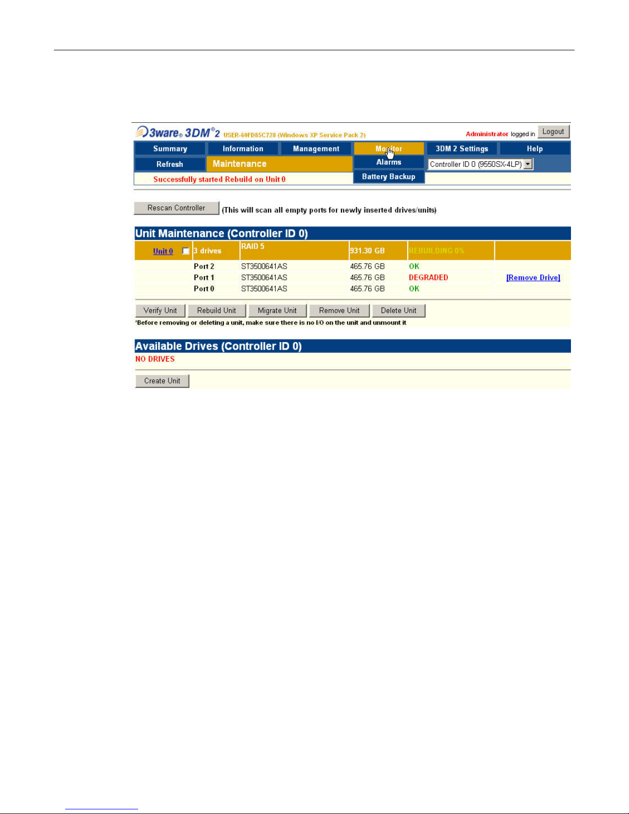
12) Observe that the replacement drive has now been incorporated into the RAID 5 array as
illustrated in Figure 2-43 (note that this array is still shown as being DEGRADED).
Figure 2-43.
When the new disk has been fully integrated into the array, the interface will reflect the
completion of the rebuild.
Note: This rebuild process can take a significant amount of time (14 hours in the case of our
example using 400 GB disks).
Note: The rebuild process is performed in the background, so you can continue to use your
system while the rebuild is taking place.
Configuring the RAID Array
(with Hot Spare and System Partition on RAID Array)
Note that these discussions reflect system configurations that have the system partition established
on the RAID array itself (leaving a hot-spare drive) as illustrated in Figure 2-44. Configurations with a
separate system drive are discussed earlier in this chapter.
When you take possession of your MaxPac 8230 XRA2/3, the RAID system will already have been
established, initialized, and verified. The instructions in this section are intended to address those rare
situations where you need to replace a degraded/failed drive or you wish to rebuild the RAID system
from the ground up.
Your MaxPac system can contain up to four SATA hot-swappable hard disk drives presented in a
4-drive disk caddy. This caddy is located on the lower left-hand side of the main chassis under the
"Baghdad Filter" assembly as shown to the left of Figure 2-44 (the numbering of the disks is as shown
to the right of Figure 2-44). The main array – including the system partition – occupies disks 00, 01,
Page 38
32 MaxPac Dual/Triple-Screen 8230 XRA2/3-Series User Operation and Maintenance Guide
and 02, leaving disk 03 as the hot-spare (note that this is the initial/default configuration; once the hotspare disk has been deployed as discussed below, the failed-and-replaced disk will assume the role
of the new hot-spare).
Figure 2-44
Establishing the Array and Reloading the System Image
These discussions assume that you are reestablishing a system from the ground up, and that you
have four new disks in your disk caddy.
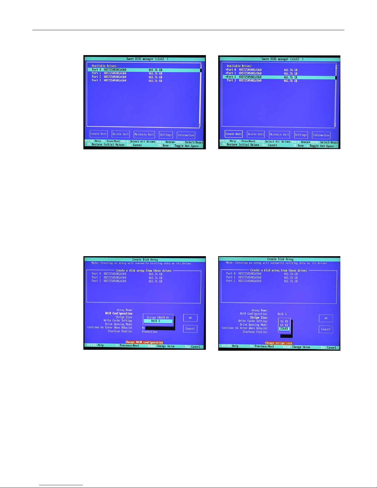
1) Start to power-up the system. When you see the BIOS message "<Alt-3> to access 3ware BIOS
Manager" (Figure 2-45) press and hold the <ALT> (alternate) key and – while still holding this key
– press the number "3" key. This will invoke the 3ware BIOS manager; in most cases, you will be
presented with a warning screen as shown in Figure 2-46.
2) Press any key to continue, which will take you fully into the 3ware BIOS Manager. Observe that
the four disks are shown on the screen, but no drives are initially selected (Figure 2-47).
Figure 2-45
Figure 2-46
Page 39
MaxPac Dual/Triple-Screen 8230 XRA2/3-Series User Operation and Maintenance Guide 33
Figure 2-47
Figure 2-48
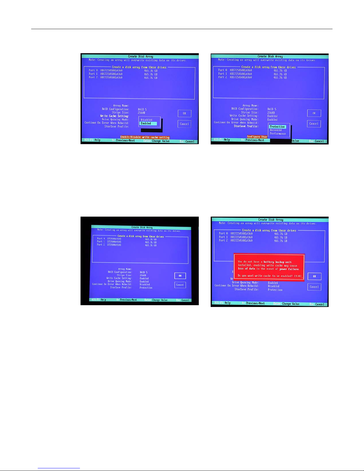
3) Use the up/down arrow keys to highlight disks 00, 01, and 02 in turn; as each disk is highlighted,
press the <Enter> key to select it (selected disks are indicated with an asterisk '*' character as
shown in Figure 2-48). (Note that the reason disk 03 is not selected is that this is being reserved
as the hot-spare.)
4) Use the <Tab> key to highlight the Create Unit option (Figure 2-48), then press the <Enter> key
to key to invoke the Create Disk Array screen.
5) Use the up/down arrow keys to highlight the RAID Configuration item, and then press the
<Enter> key to access an associated pop-up dialog (Figure 2-49).
6) Now use the up/down keys to highlight the RAID 5 option and then press the <Enter> key to
select this option.
7) Next, use the up/down arrow keys to highlight the Stripe Size item, and then press the <Enter>
key to access an associated pop-up dialog (Figure 2-50).
8) Use the up/down arrow keys to highlight the 256 KB option, and then press the <Enter> key to
select this option.
9) Use the up/down arrow keys to highlight the Write Cache Setting item, and then press the
<Enter> key to access an associated pop-up dialog (Figure 2-51).
10) Use the up/down arrow keys to highlight the Enabled option, and then press the <Enter> key to
select this option.
Figure 2-49
Figure 2-50
Page 40
34 MaxPac Dual/Triple-Screen 8230 XRA2/3-Series User Operation and Maintenance Guide
Figure 2-51
Figure 2-52
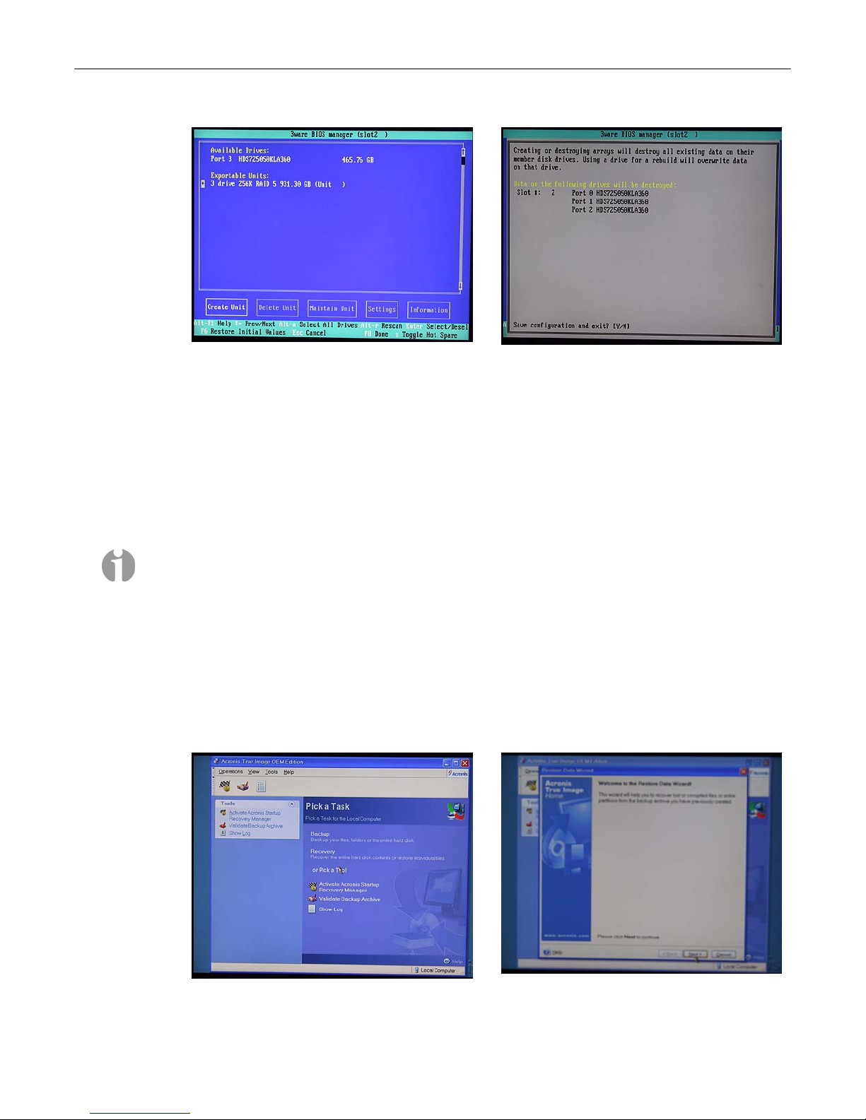
11) Use the up/down arrow keys to highlight the StorSave Profile item, and then press the <Enter>
key to access an associated pop-up dialog (Figure 2-52).
12) Use the up/down arrow keys to highlight the Protection option, and then press the <Enter> key
to select this option.
13) Use the up/down/right/left arrow keys to highlight the OK item (Figure 2-53) and then press the
<Enter> key to save your changes.
Figure 2-53
Figure 2-54
14) You will be presented with a warning dialog as shown in Figure 2-54. Press the Y (yes) key to
allow the write cache to be enabled [note that this mode significantly improves performance, but it
can result in a loss of data in the event of a power failure, so MaxVision STRONGLY
recommends the use of an uninterruptible power supply (UPS) with your system.
15) At this point, you will be presented with a summary description of the RAID array you have
defined (Figure 2-55).
16) Observe that this screen shows the array (3 drives) and the remaining uncommitted drive. Use
the up/down arrow keys to highlight the uncommitted drive and press the <Enter> key to select it
(the fact this has been selected will be indicated with an asterisk '*' character).
17) Now press the 'S' key to designate this selected drive as being the hot-spare (an annotation will
appear next to the drive confirming this status).
Page 41
MaxPac Dual/Triple-Screen 8230 XRA2/3-Series User Operation and Maintenance Guide 35
Figure 2-55
Figure 2-56
18) Press the <F8> key to request that your array be committed and to exit the 3ware BIOS
setup utility.
19) You will be presented with a warning screen as shown in Figure 2-56. Before you do anything
else, ensure that the bootable recovery DVD supplied in the accessory pack is in the system's
CD/DVD drive. In the case of a multiple DVD image, ensure Disk #1 is in the drive. Then press
the Y (yes) key in order to establish your array, exit the 3ware BIOS setup utility, and
automatically reboot the machine.
Note: If you are using an image CD/DVD you've created yourself as discussed in Appendix A,
and if that CD/DVD (or the first CD/DVD in a set) has the Acronis Bootable Rescue Media
software on it, then simply insert this disk in the drive and proceed to point 20 below.
Alternatively, if your CD/DVD does not have the Acronis Bootable Rescue Media software on it,
then first insert the bootable recovery DVD supplied by MaxVision in the drive and reboot as
discussed in point 20 below. However, before proceeding to point 21, remove the bootable
recovery DVD supplied by MaxVision from the drive and replace it with the first disk from your
own image.
20) The system will automatically reboot itself from the recovery disk in the DVD drive. Following
the Acronis splash, you will be presented with the Pick a Task page in the Acronis True Image
application (Figure 2-57).
Figure 2-57
Figure 2-58
Page 42
36 MaxPac Dual/Triple-Screen 8230 XRA2/3-Series User Operation and Maintenance Guide
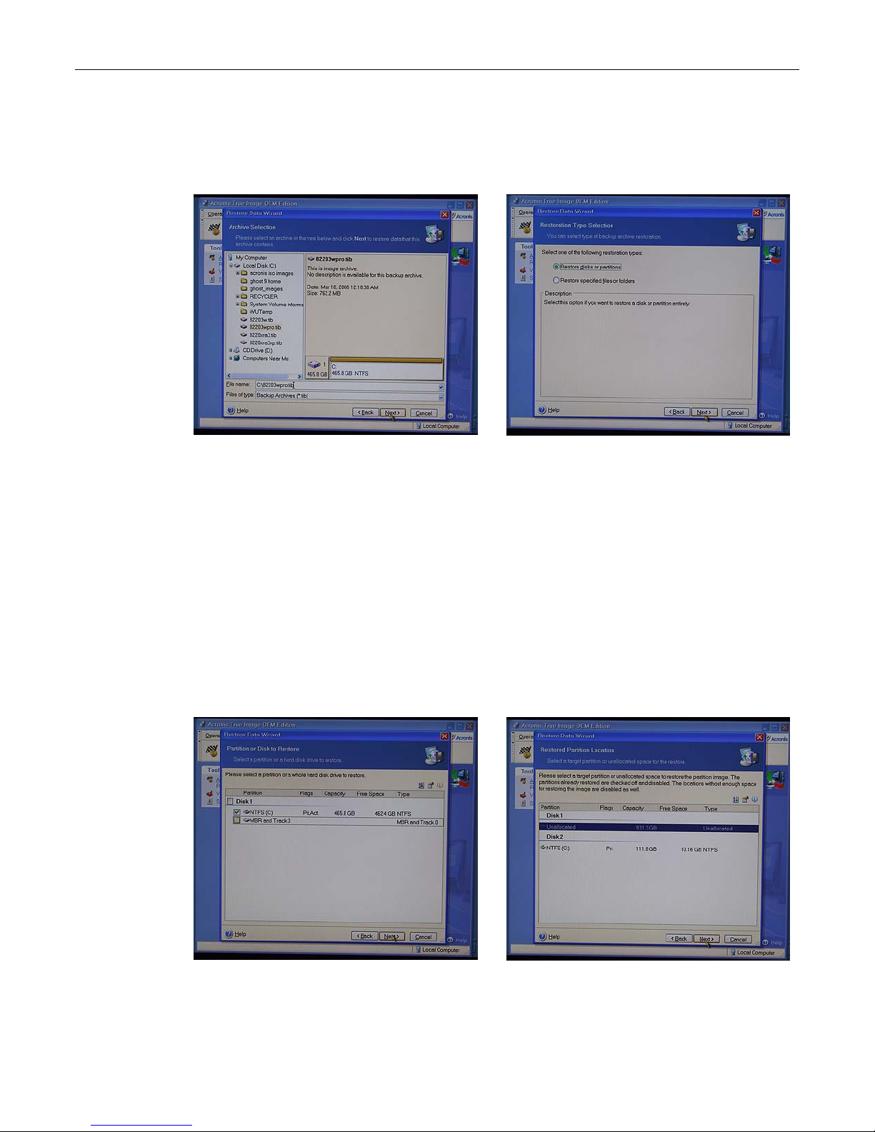
21) Click the Recovery item to be presented with the first page from the Restore Data Wizard
(Figure 2-58).
22) Click the Next button to be presented with the Archive Selection screen (Figure 2-59).
Figure 2-59
Figure 2-60
23) Ensure that the CD Drive item in the left-hand selection pane is expanded (if not, click the '+'
icon next to this item) and then use the mouse to click on the image (*.tib) file you will see there
(Figure 2-59).
Note: In the case of a multi-CD/DVD image set, the system will present you with a message
saying that this is not the last created volume in the archive and requesting you to insert the
last created volume. In this case, replace the current CD/DVD with the last disk from the set,
click on the *.tib file on this disk, and proceed to point 24 (at some stage you will be prompted
to return to the first disk).
24) Click the Next button to be presented with the Restoration Type Selection page (Figure 2-60).
25) Select the Restore Disks or Partition item and then click the Next button to be presented with
the Partition or Disk to Restore page (Figure 2-61).
26) Select the NTFS (C) option (a tick-mark indicates that the option has been selected) and then
click the NEXT button to be presented with the Restored Partition Location page (Figure 2-62).
Figure 2-61
Figure 2-62
Page 43
MaxPac Dual/Triple-Screen 8230 XRA2/3-Series User Operation and Maintenance Guide 37
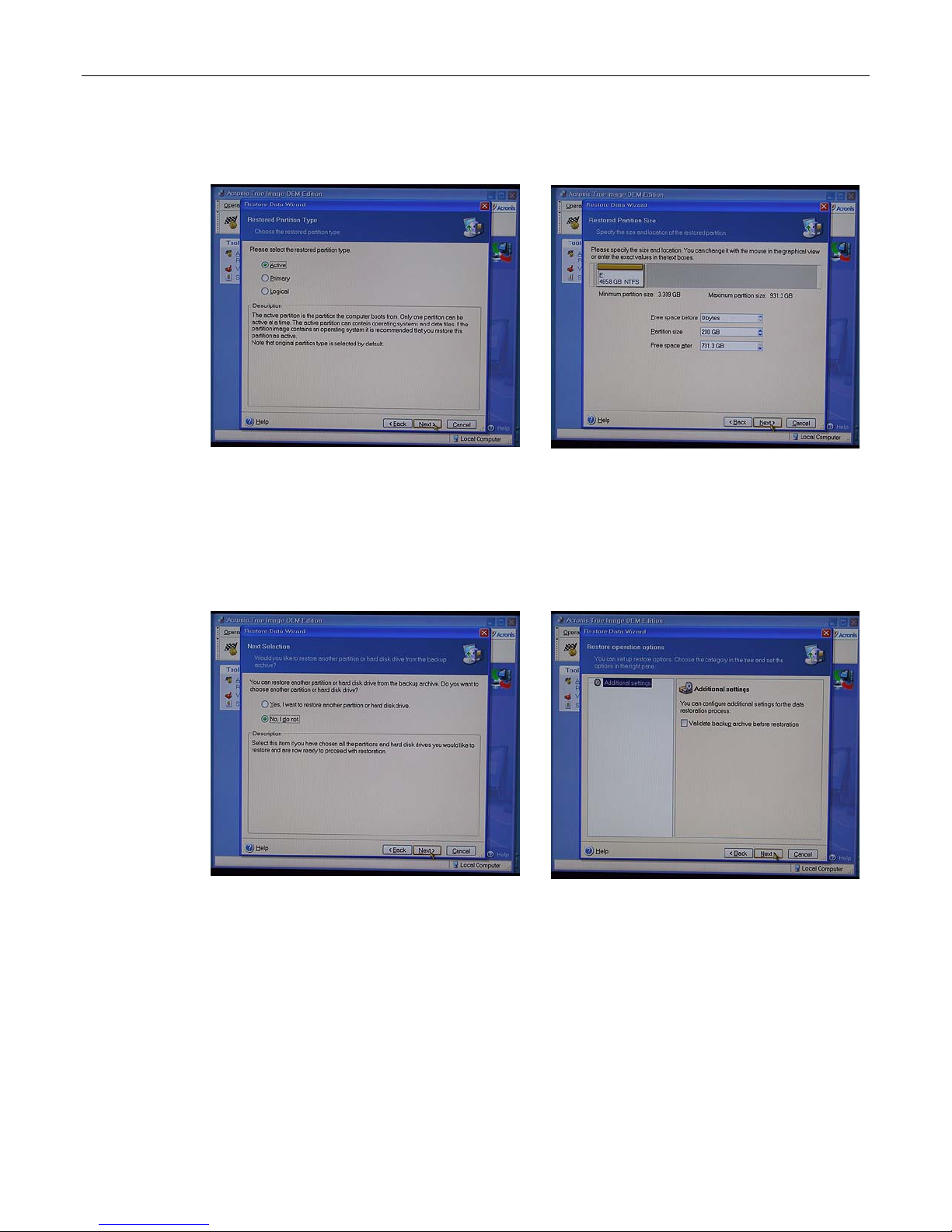
27) Select the Unallocated (Disk 1) item and then click the Next button to be presented with the
Restored Partition Type page (Figure 2-63).
Figure 2-63
Figure 2-64
28) Select the Active item and then click the Next button to be presented with the Restored
Partition Size page (Figure 2-64).
29) We have chosen to establish a 200 GB system partition in this example; the remaining "Free
Space" will automatically be allocated to the data portion of the RAID 5 array. Click the Next
button to be presented with the Next Selection window (Figure 2-65)
Figure 2-65
Figure 2-66
30) Select the No, I Do Not option and then click the Next button to be presented with the Restore
Operation options page (Figure 2-66).
31) Simply click the Next button to be presented with the Restore Data Wizard summary screen
(Figure 2-67)
Page 44
38 MaxPac Dual/Triple-Screen 8230 XRA2/3-Series User Operation and Maintenance Guide
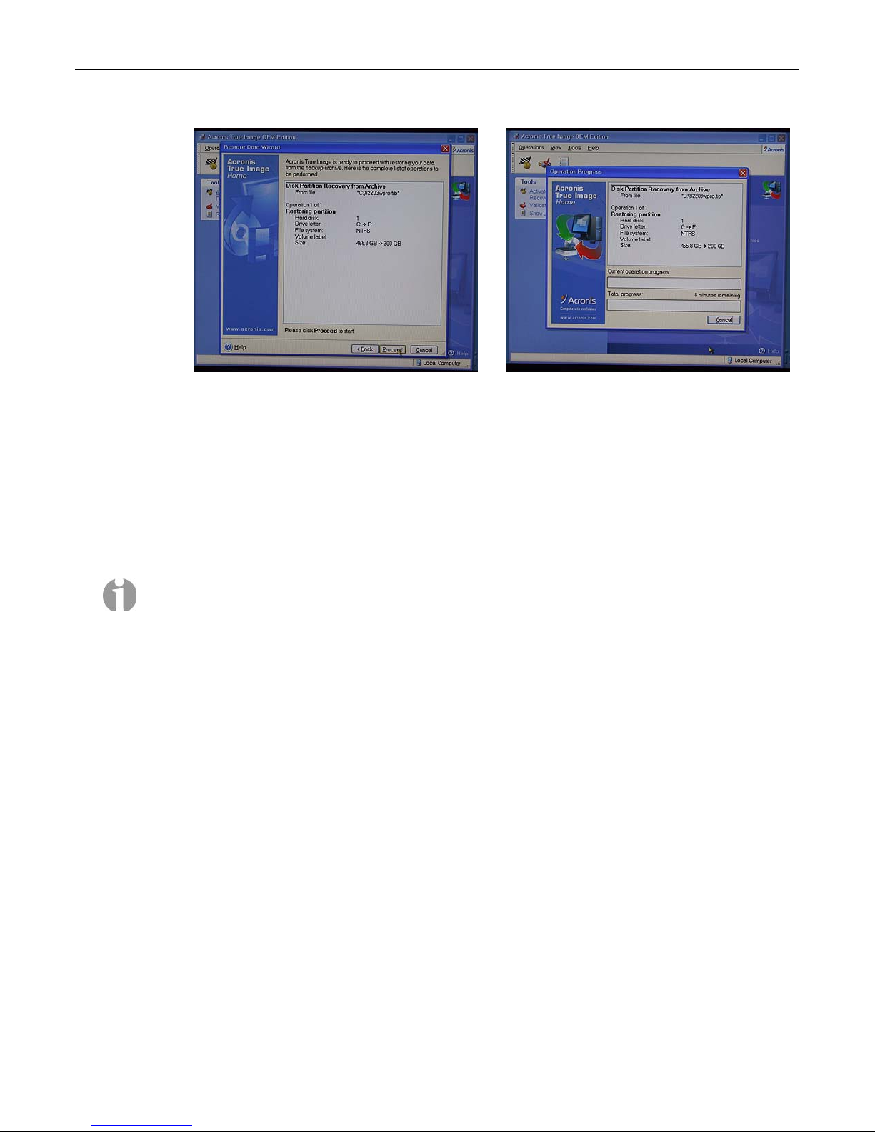
Figure 2-67
Figure 2-68
32) Click the Proceed button to initiate the restoration, at which time you will be presented with the
Operation Progress dialog (Figure 2-68), which will reflect the status of the restoration. (In the
case of a multi-DVD image, the system will inform you as and when to insert subsequent
DVDs).
33) Once the restoration process has been completed, eject the DVD from the CD/DVD drive,
power-down the system by holding the Soft-Power button on top of the center display for
approximately five seconds, and then power-up the machine using the Soft Power button to
boot-up into Windows.
Note: Once you have re-loaded the original MaxVision-supplied image, you will also have to rerun the initialization procedures – including re-activating/re-registering your OS license – as
described earlier in this manual.
34) After the system has booted up into Windows (and you've re-run the initialization procedures as
noted above), right-click on the My Computer icon and then select the Manage option. In the
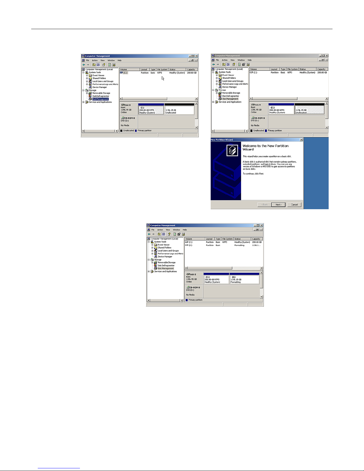
ensuing Computer Management dialog, click on the Disk Management item (Figure 2-69).
35) Right-mouse-click in the Unallocated area and select the New Partition item in order to be
presented with the New Partition Wizard as shown in Figure 2-70.
36) Click the Next button, then select the Perform a Quick Format option (ensure the File System
type is set to NTFS), and then click the OK button. The Computer Management window will
reflect your newly formatted partition (Figure 2-71).
Page 45
MaxPac Dual/Triple-Screen 8230 XRA2/3-Series User Operation and Maintenance Guide 39
Figure 2-69
Figure 2-70
Figure 2-71
Page 46
40 MaxPac Dual/Triple-Screen 8230 XRA2/3-Series User Operation and Maintenance Guide
Rebuilding an Existing (Failed) 3ware RAID 5 Array
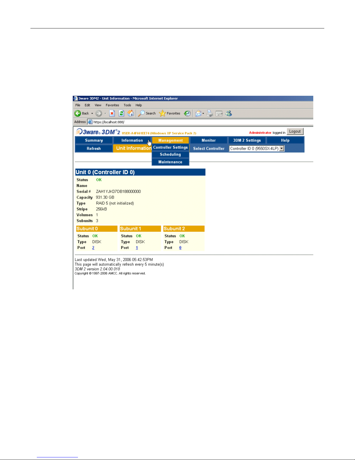
The discussions in this section assume that you originally have a good, working RAID 5 array
(consisting of 3 drives for the array and 1 Hot Spare). In this case, if you double-click the Connect to
3DM 2 icon on your desktop and login to the ensuing webpage using the default password (which is
3ware), you will see that the status of your array looks something like that shown in Figure 2-72.
Once you have observed this good array, exit out of the 3DM 2 web interface. At some stage, one of
the disks in the array may start to degrade or go completely off-line. For the purposes of these
discussions, we are going to power down the system, physically remove Disk 01 from the array
(thereby simulating a catastrophic failure on this disk) and power up the system back up again.
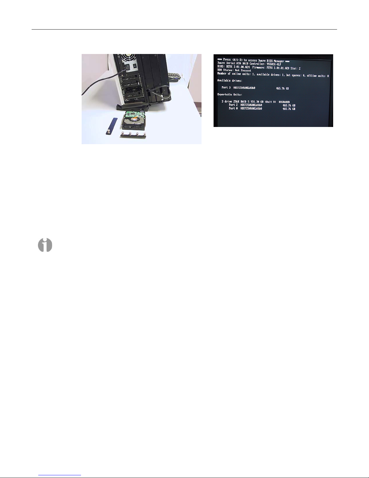
1) Power down the system and remove the center data disk (Disk 01) as shown in Figure 2-73.
2) Power the system back up again. The BIOS detects the fact that there is a problem with the RAID
array and displays an appropriate message (Figure 2-74). Press the <Pause Break> key to freeze
the display; from this (and Figure 2-44) you will be able to determine which drive has failed. (In
the case of our example, the RAID array is shown as being "Degraded" and only Ports 0 and 2
are shown as being available.)
3) Press the <Pause Break> key again to un-freeze the display. The system will automatically bring
the hot-spare drive online and integrate it into the array.
4) As soon as possible after the array has been reconstructed as discussed in point 3, power down
the system, remove the failed drive (in this case it was previously removed to simulate the
failure), and replace it with a good drive of the same type and capacity.
Figure 2-72
Page 47
MaxPac Dual/Triple-Screen 8230 XRA2/3-Series User Operation and Maintenance Guide 41
Figure 2-73
Figure 2-74
5) Start to power-up the system. When you see the BIOS message "<Alt-3> to access 3ware BIOS
Manager", press and hold the <ALT> (alternate) key and – while still holding this key – press the
number "3" key. This will invoke the 3ware BIOS manager; in most cases, you will be presented
with a warning screen; press any key to continue, which will take you fully into the 3ware BIOS
Manager.
6) Observe that this screen shows the array (3 drives) and the remaining uncommitted drive (the
new drive you've just added to the system). Use the up/down arrow keys to highlight the
uncommitted drive and press the <Enter> key to select it (the fact this has been selected will be
indicated with an asterisk '*' character).
Note: If this drive was ever part of a previous 3ware RAID array, it will show up as a "Failed
Array" comprising only a single drive. In this case, use the <Tab> key to select the Delete Unit
option and then press the <Enter> key to select this option and delete the drive as an array.
7) Now press the 'S' key to designate this selected drive as being the new hot-spare (an annotation
will appear next to the drive confirming this status).
8) Press the <F8> key to exit the 3ware BIOS utility and automatically reboot the system.
9) Power the system up all the way into Windows.
Page 48

42 MaxPac Dual/Triple-Screen 8230 XRA2/3-Series User Operation and Maintenance Guide
Chapter 3: Module Replacement
and Upgrade Procedures
Page 49

MaxPac Dual/Triple-Screen 8230 XRA2/3-Series User Operation and Maintenance Guide 43
Introduction
The instructions in this chapter describe how to replace and upgrade various modules in your
MaxPac unit.
Note: Generally speaking, you should only access the MaxPac internals under the direction of
MaxVision support. In some cases, performing unauthorized procedures or using components that
have not been tested and approved by MaxVision may invalidate your warranty.
Note: Power-down your MaxPac system (shut down Windows® and then turn the hard power switch
to its Off position) and then remove the power cable before performing any of the procedures
discussed in this chapter. Also please be aware of static discharge when working on your MaxPac. In
General, touch the metal part of the chassis to discharge any static prior to handling any delicate
electronic parts.
Note: When accessing the system internals and/or performing module upgrade procedures, you are
quickly going to end up with a lot of screws and other small items. In order to keep track of things and
to prevent misplacing any parts, it is strongly recommended to have a plastic container divided into
small compartments and to label these compartments as you work.
Required Tools and Techniques
Most of the module replacement and upgrade procedures discussed in this chapter can be performed
using only a pair of #1 (small tip) and #2 (regular tip) Phillips screwdrivers. However, some
procedures will require additional tools as discussed in Appendix C.
Note: It is extremely important that you use only high-quality tools so as to avoid any slippage and
stripping of screw heads and threads. Furthermore, in order to avoid any slippage, it is VERY
important to apply adequate force in the form of firm and steady pressure. See Appendix C for
details on the tools required to service the system.
Note: It is highly recommended that you use magnetized screwdrivers so as to prevent screws from
dropping inside the case and/or aiding in retrieving them if they do drop inside the case. (If your
screwdriver isn’t already magnetized, you can make it so by repeatedly “stroking” the blade with a
permanent magnet.
Names and Types of Screws
MaxPac X-Class systems use a variety of different screw types. In order to help you follow the
instructions in this chapter, details on these screws are provided in Appendix C.
Page 50
44 MaxPac Dual/Triple-Screen 8230 XRA2/3-Series User Operation and Maintenance Guide
Flat Panel Display Module (Left-Hand Screen)
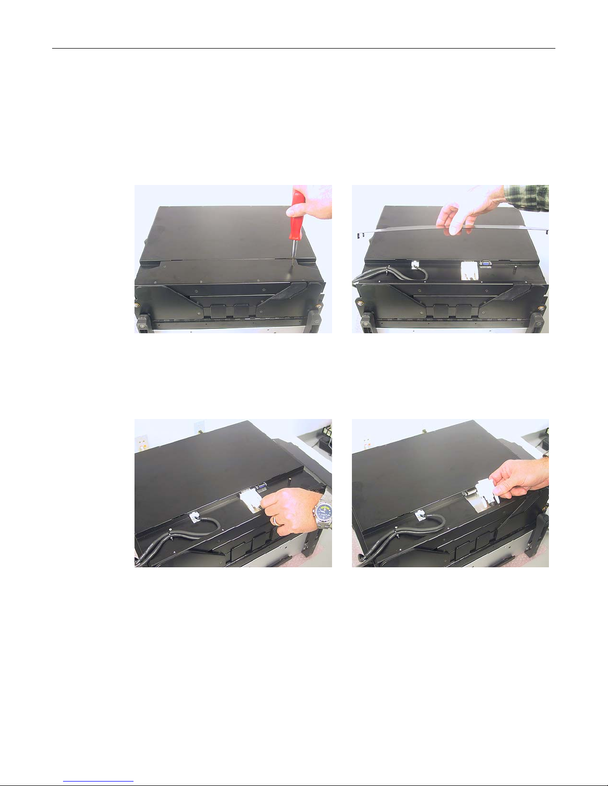
1) Lay the system flat on the table with the displays in the closed position and facing upwards (it is
recommended that you lay the system on bubble wrap in order to protect the finish).
2) Use a Phillips #1 screwdriver to remove the six 4-40 3/16" black countersunk screws holding the
left-hand screen's monitor cable access panel (Figure 3-1).
Figure 3-1
3) Gently lift the left-hand screen's monitor cable access panel away from the system (Figure 3-2).
4) Unscrew the jack screws holding the DVI data cable connector (Figure 3-3) and gently pull this
connector away from the display (Figure 3-4).
Figure 3-3
5) Press down on the release catch holding the power cable and gently pull this connector away
from this display (Figure 3-5).
Figure 3-2
Figure 3-4
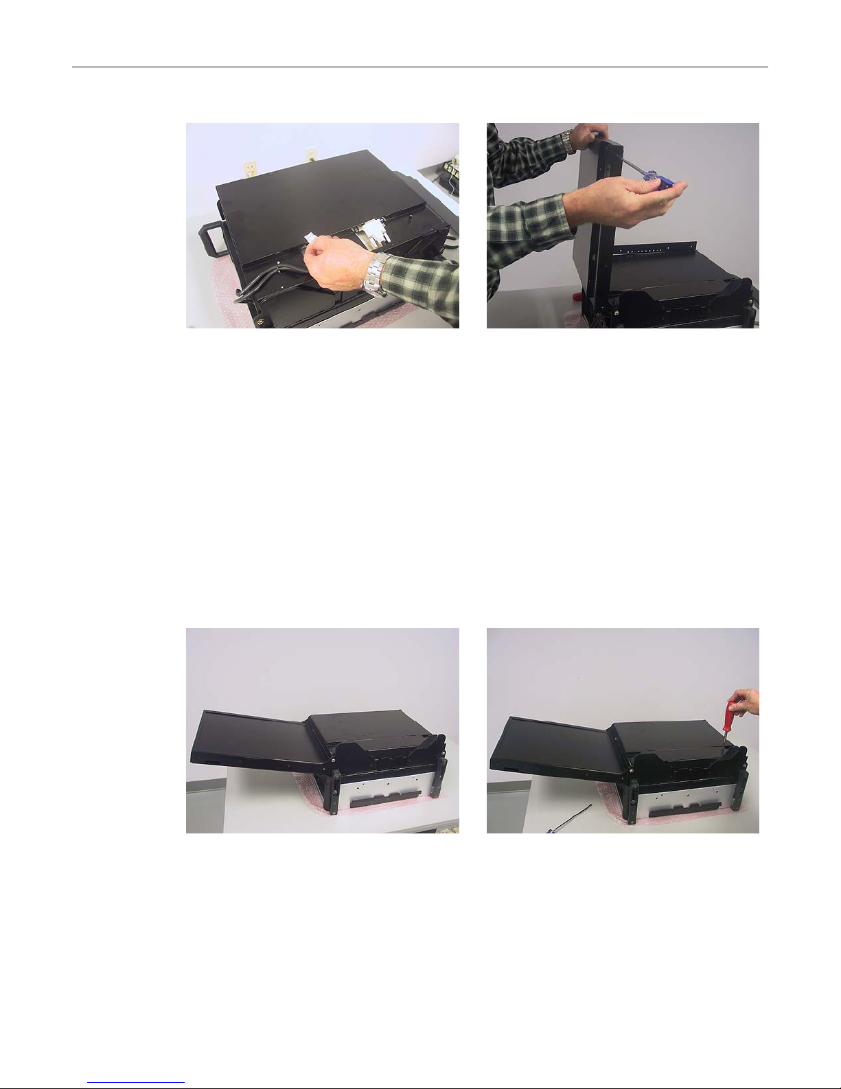
6) Observe the cable tie attaching the power and data cables to a standoff post mounted to the left
of the screen assembly (this cable-tie is shown just to the left of the hand in Figure 3-5). Do not
cut this cable tie, but instead simply unhook the tie from the stand-off post.
Page 51
MaxPac Dual/Triple-Screen 8230 XRA2/3-Series User Operation and Maintenance Guide 45
Figure 3-5
7) Open the left-hand screen to a vertical position, use a Phillips #2 screwdriver to remove the eight
6-32 1/4" black countersunk screws – four on each site – holding the screen to its hinge bar
(Figure 3-6), and then lift the screen away.
8) Perform the above steps in reverse order to replace the failed screen with the new unit as
supplied by MaxVision support.
Figure 3-6
Flat Panel Display Module (Right-Hand Screen)
1) Lay the system flat on the table with the displays in the closed position and facing upwards (it is
recommended that you lay the system on bubble wrap in order to protect the finish). If your
MaxPac system has three screens, unfold the left-hand screen as shown in Figure 3-7.
2) Use a Phillips #1 screwdriver to remove the six 4-40 3/16" black countersunk screws holding the
right-hand screen's monitor cable access panel (Figure 3-8).
3) Gently lift the left-hand screen's monitor cable access panel away from the system.
4) Unscrew the jack screws holding the DVI data cable connector and gently pull this connector
away from the display (Figure 3-9).
Figure 3-7
Figure 3-8
Page 52
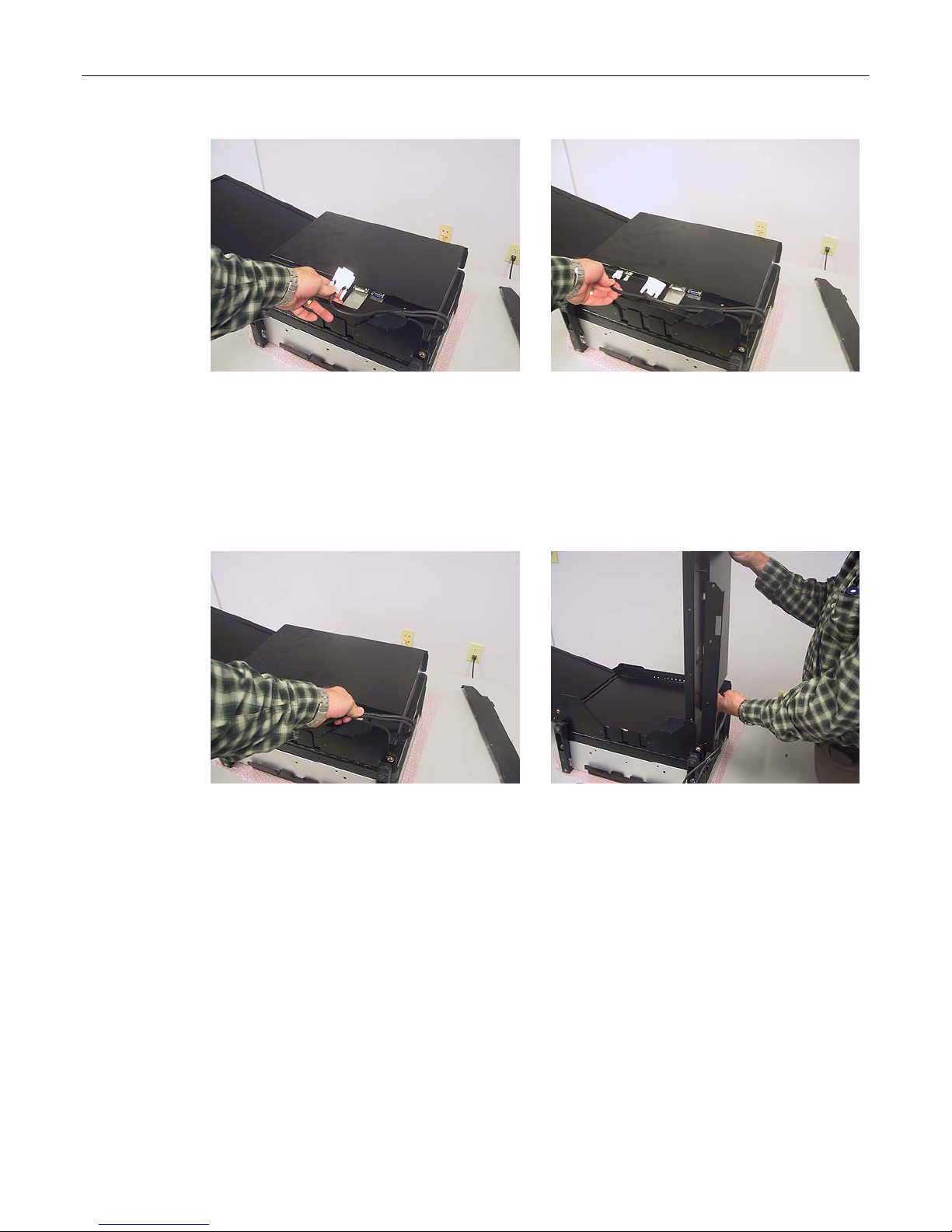
46 MaxPac Dual/Triple-Screen 8230 XRA2/3-Series User Operation and Maintenance Guide
Figure 3-9
5) Press down on the release catch holding the power cable and gently pull this connector away
from this display (Figure 3-10).
6) Observe the cable tie attaching the power and data cables to a standoff post mounted to the right
of the screen assembly. Do not cut this cable tie, but instead simply unhook the tie from the
stand-off post (Figure 3-11).
Figure 3-11
Figure 3-10
Figure 3-12
7) Open the right-hand screen to a vertical position, use a Phillips #2 screwdriver to remove the
eight 6-32 1/4" black countersunk screws – four on each site – holding the screen to its hinge bar
(similar to the procedure for the left-hand screen as shown in Figure 3-6), and then lift the screen
away (Figure 3-12).
8) Perform the above steps in reverse order to replace the failed screen with the new unit as
supplied by MaxVision support.
Flat Panel Display Module (Center Screen)
1) Lay the system flat on the table with the displays in the closed position and facing upwards (it is
recommended that you lay the system on bubble wrap in order to protect the finish). If your
MaxPac system has three screens, unfold the left- and right-hand screens as shown in Figure
3-13 (if your MaxPac system has only two screens, unfold the right-hand screen.)
Page 53
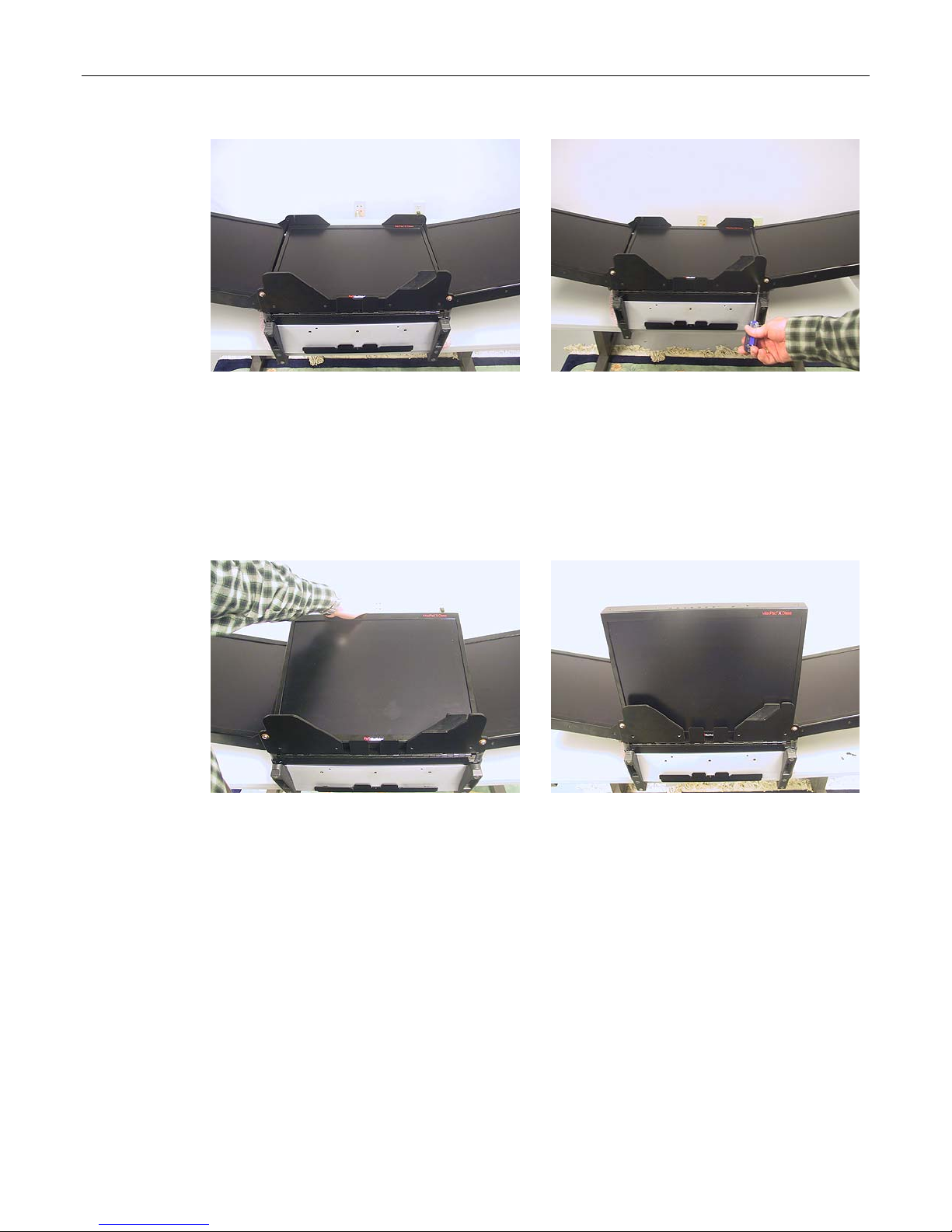
MaxPac Dual/Triple-Screen 8230 XRA2/3-Series User Operation and Maintenance Guide 47
Figure 3-13
Figure 3-14
2) Use a Phillips #2 screwdriver to remove the eight 6-32 1/4" black countersunk screws – four on
each site – holding the screen to the wing brackets, which are in turn attached to the main
chassis (Figure 3-14).
3) Lift the center screen into a vertical position standing against the cable-side pair of wing brackets
as illustrated in Figures 3-15 and 3-16 (as these monitors are expensive items, it is strongly
recommended that you keep hold of the screen when it is in this vertical position).
Figure 3-15
Figure 3-16
4) On the other side of the screen (with regard to Figure 3-16), observe the monitor tilt-stand
components lying in/on the main chassis as indicated by the pointing finger in Figure 3-17. It is
very important to ensure that these components remain flat and interleaved.
Page 54
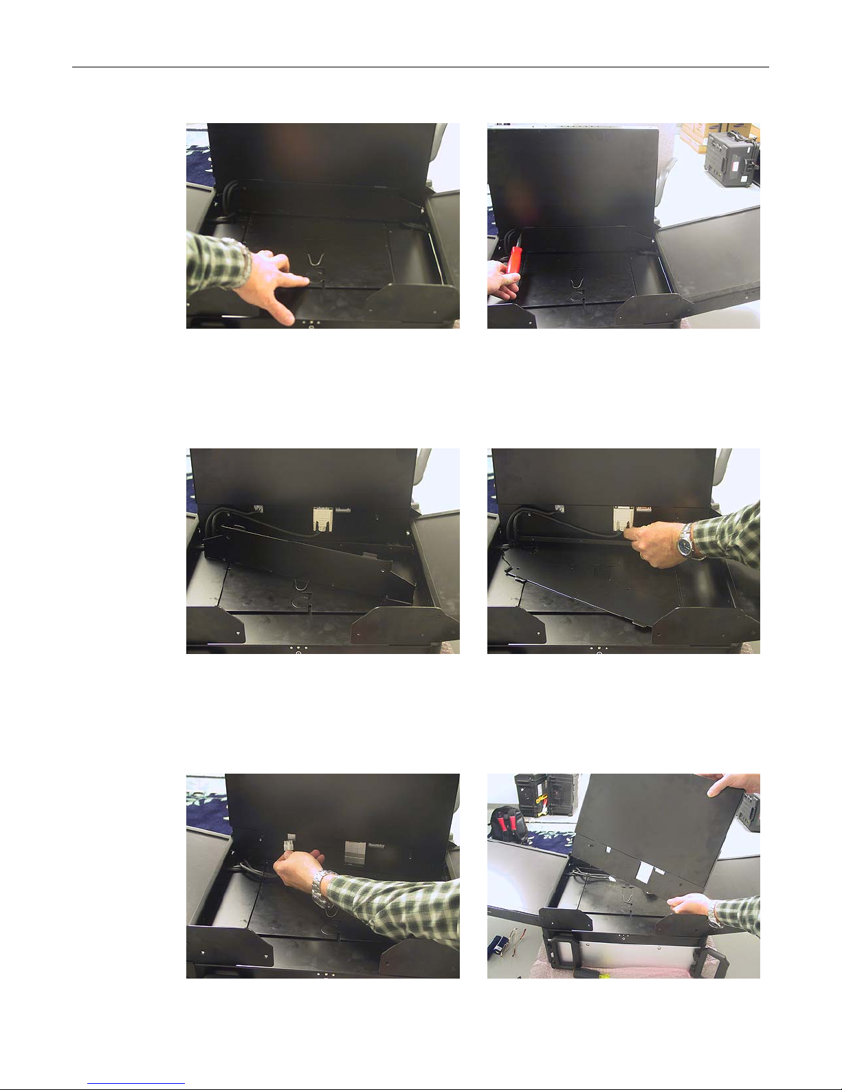
48 MaxPac Dual/Triple-Screen 8230 XRA2/3-Series User Operation and Maintenance Guide
Figure 3-17
Figure 3-18
5) Use a Phillips #1 screwdriver to remove the six 4-40 3/16" black countersunk screws holding the
center screen's monitor cable access panel (Figure 3-18).
6) Gently lift the center screen's monitor cable access panel away from the system (Figure 3-19).
Figure 3-19
Figure 3-20
7) Unscrew the jack screws holding the DVI data cable connector (Figure 3-20) and gently pull this
connector away from the display.
Figure 3-21
Figure 3-22
Page 55
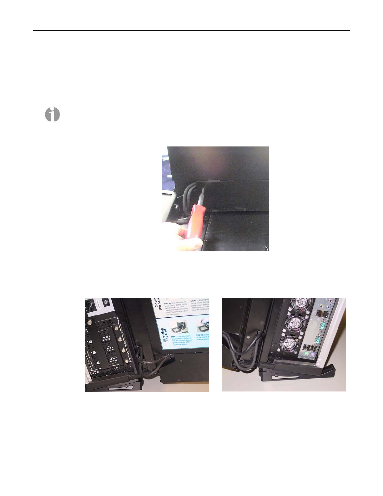
MaxPac Dual/Triple-Screen 8230 XRA2/3-Series User Operation and Maintenance Guide 49
8) Press down on the release catch holding the power cable and gently pull this connector away
from this display (Figure 3-21).
9) Lift the center screen away from the system (Figure 3-22).
10) Perform the above steps in reverse order to replace the failed screen with the new unit as
supplied by MaxVision support.
Note: When replacing the cable access cover for the center screen, observe that the cables exit
the screen assembly through the larger upper cable guide as shown in Figure 3-23.
When re-installing the center screen, once the cable access panel has been re-attached, any
excess cable must be pushed down into the main chassis.
Figure 3-23
By comparison, in the case of the left- and right-hand screens, the cables exit as shown in
Figures 3-24 and 3-25, respectively (observe that the cable service lengths for the left- and righthand screens are dictated by the cable ties as discussed in the previous sections).
Figure 3-24
Figure 3-25
Page 56
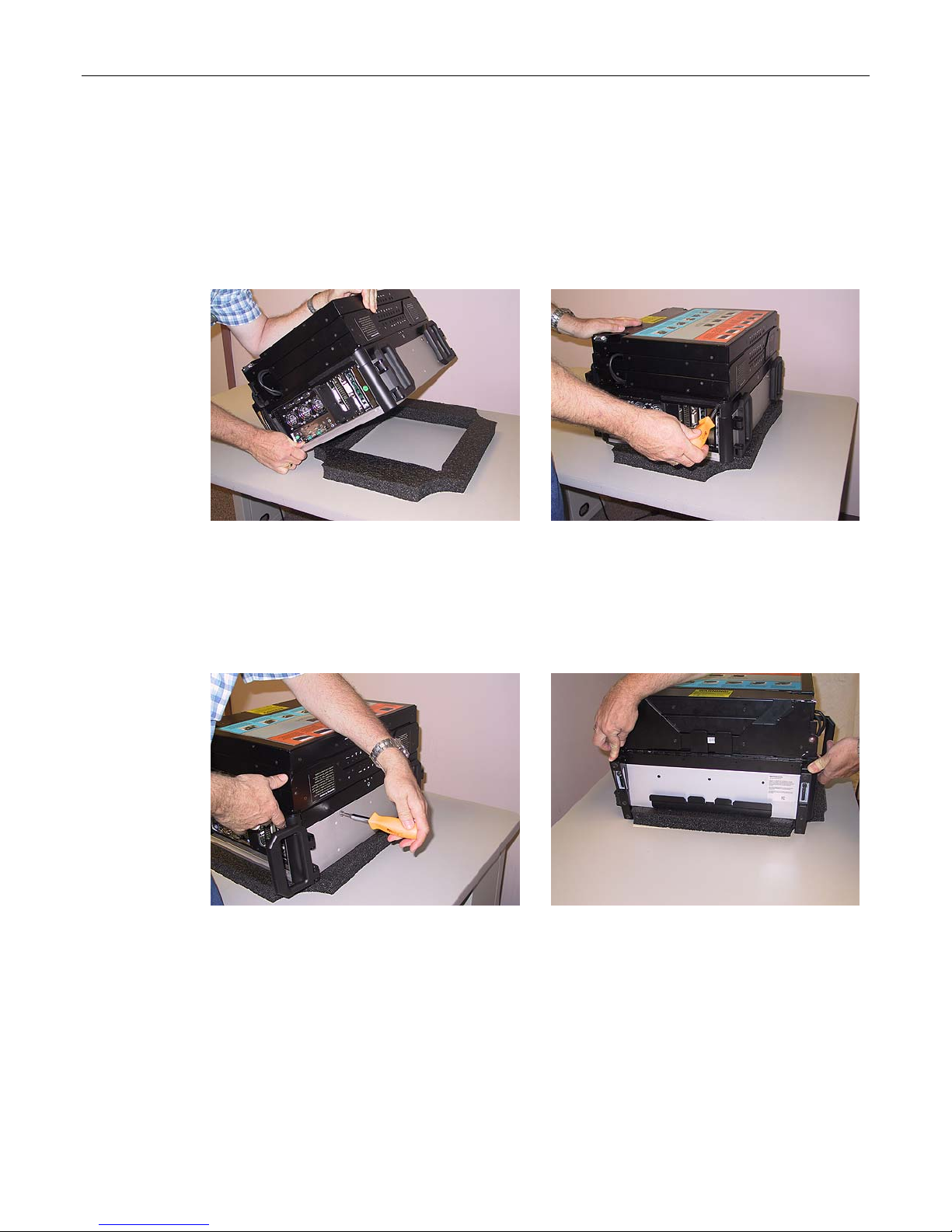
50 MaxPac Dual/Triple-Screen 8230 XRA2/3-Series User Operation and Maintenance Guide
Opening the Display Assembly into its Service Position
In order to replace and/or upgrade modules inside the MaxPac system, it is necessary to open the
display assembly into its service position as discussed below.
1) Lay the system flat on the table on top of a piece of firm, non-abrasive foam (or similar material)
capable of supporting the system's weight as shown in Figure 3-26. Observe that the displays
should be in the closed position and facing upwards.
Figure 3-26
2) Use a Phillips #2 screwdriver to remove the two 10-32 1/4" black countersunk screws holding the
screen assembly to the chassis (there is one on each side on the top-side of the system close to
the handles as illustrated in Figure 3-27).
3) Use a Phillips #2 screwdriver to remove the two 10-32 silver truss head screws on the top of the
system (Figure 3-28).
Figure 3-28
4) Press the feet down into their fully "tilted" position as shown in Figure 3-29 (this is necessary to
allow the display assembly to fully hinge up).
Figure 3-27
Figure 3-29
5) Walk around to the other side of the system (so you are facing the bottom of the system) and lift
the screen assembly as shown in Figure 3-30.
6) Squeeze the integrated support stands together as illustrated in Figure 3-30.
Page 57
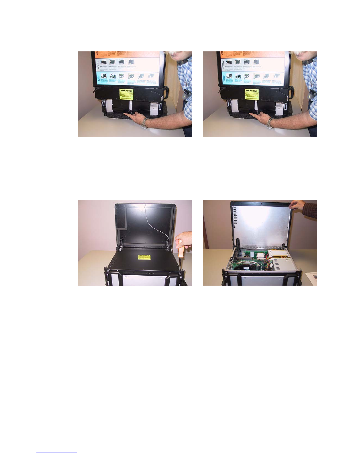
MaxPac Dual/Triple-Screen 8230 XRA2/3-Series User Operation and Maintenance Guide 51
Figure 3-30
Figure 3-31
7) Pull the support stands down to their maximum extended (service) position as illustrated in Figure
3-31 (ensure that, when you release the supports, their spring mechanism expands them back
into their locked position).
8) Return to facing the top of the system and use a Phillips #2 screwdriver to remove the five 6-32
1/4" black countersunk screws – three on the top and one on each site – holding the inner
chassis cover (Figure 3-32).
Figure 3-32
Figure 3-33
9) Observe that the inner chassis cover is hinged. Gently raise the inner chassis cover to its vertical
position leaning back against the display assembly (Figure 3-33).
Page 58

52 MaxPac Dual/Triple-Screen 8230 XRA2/3-Series User Operation and Maintenance Guide
Memory
Note: Due to the fact that high-end computer systems can experience a host of memory compatibility
issues and problems, you should only use replacement and/or additional memory sticks supplied by
MaxVision.
Note: The MaxPac 8230 uses a Fully Buffered DDR2 memory (FB-DIMM or FBD). Specifically the
MaxPac 8230 uses FBD DDR2 667MHz. The difference between FBD and regular DDR2 is a chip on
each module called the AMB (Advanced Memory Buffer), which buffers all data/address/command
requests to the DRAM devices. This buffering allows up to 12 GB of memory to be installed in the
MaxPac 8230. FB-DIMMs mandate that memory sticks be used in pairs, with each pair having the
same size/capacity/speed. The first pair of FBD memory sticks occupies the first and third DIMM slots
(labeled DIMM1A and DIMM2A on the motherboard); the second pair of FBD memory sticks occupies
the second and fourth DIMM slots (labeled DIMM1B and DIMM2B on the motherboard).
Note: In the event that you begin to experience problems with the memory that is already resident
in your MaxPac, you must first determine which stick has failed under the direction of MaxVision
support.
Note: The BIOS will always report the true amount of physical memory that is present in the system.
This may be as much as 12 GB. However, the actual amount of memory that can be seen by the
system is determined by the main operating system (OS). With regard to the 32-bit Windows® XP
Professional operating system, for example, in the case of a MaxPac 8230 XRA2 (dual-screen)
configuration, the maximum amount of memory reported in the System Information dialog is 3 GB;
by comparison, in the case of a MaxPac 8230 XRA3 (triple-screen) configuration, the maximum
amount of memory reported in the system information dialog is 2 GB. (Further note that – even when
the OS reports 3 GB for the dual-screen configuration – the maximum amount of shared user space
is actually only 2 GB.) by comparison, in the case of the 64-bit Windows XP Professional x64 Edition
of the operating system, the System Information dialog will accurately report the true amount of
physical memory (which can theoretically be up to 128 GB) and all of this memory will be available to
applications running on the system.
1) Open the display assembly into its service position as discussed earlier in this chapter.
2) In order to remove and replace a memory stick, gently press down-and-out on the two plastic
“rabbit-ears” at either side of the stick which will cause it to pop out, and then remove the stick
from the system (Figure 3-34).
Figure 3-34
Figure 3-35
Page 59
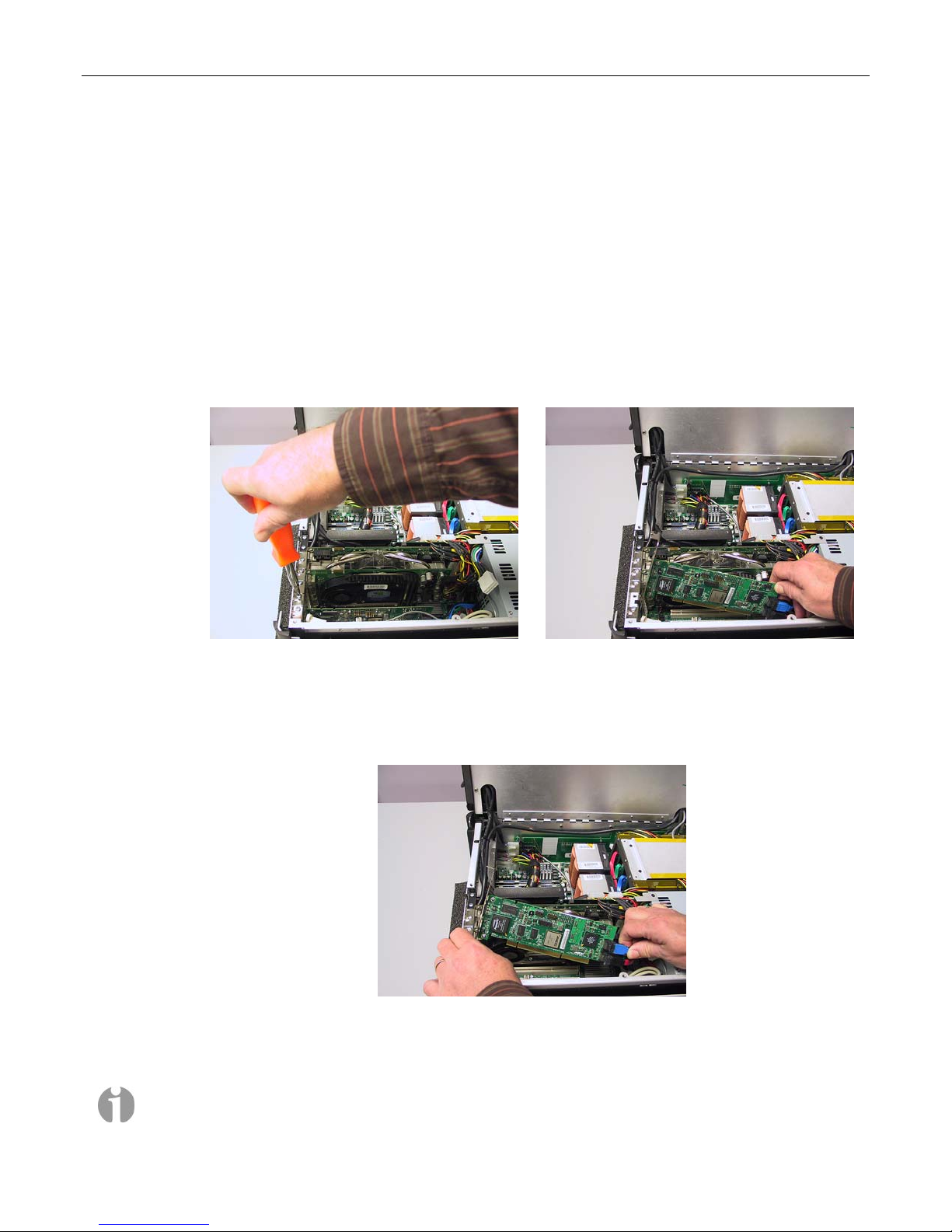
MaxPac Dual/Triple-Screen 8230 XRA2/3-Series User Operation and Maintenance Guide 53
3) Observe that the memory sticks are keyed such that they can only be inserted one way. Take the
new (replacement) memory stick sent to you by MaxVision support and gently press it down into
the original slot on the motherboard.
4) Return the system to its initial condition by reversing the order of the operations discussed at the
beginning of this section.
PCI Cards (General)
1) Open the display assembly into its service position as discussed earlier in this chapter.
2) If you are replacing an existing PCI card, use a Phillips #2 screwdriver to remove the 6-32 screw
attaching the card’s retaining bracket to the inner chassis as shown in Figure 3-36. (If you are
adding a new card, remove the corresponding blanking plate screw.)
Figure 3-36
3) Gently pull out the old card as shown in Figure 3-37.
4) This particular example features a SATA RAID controller card. In this case, you also need to
disconnect the data cables from the card as shown in Figure 3-38 (see notes below).
Figure 3-38
5) Take the new/replacement PCI card and incorporate it into the system by performing the steps
described above in reverse order.
Figure 3-37
Note: It is important to ensure that the data cables are attached to the new card in the same
positions as they occupied on the original card.
Page 60
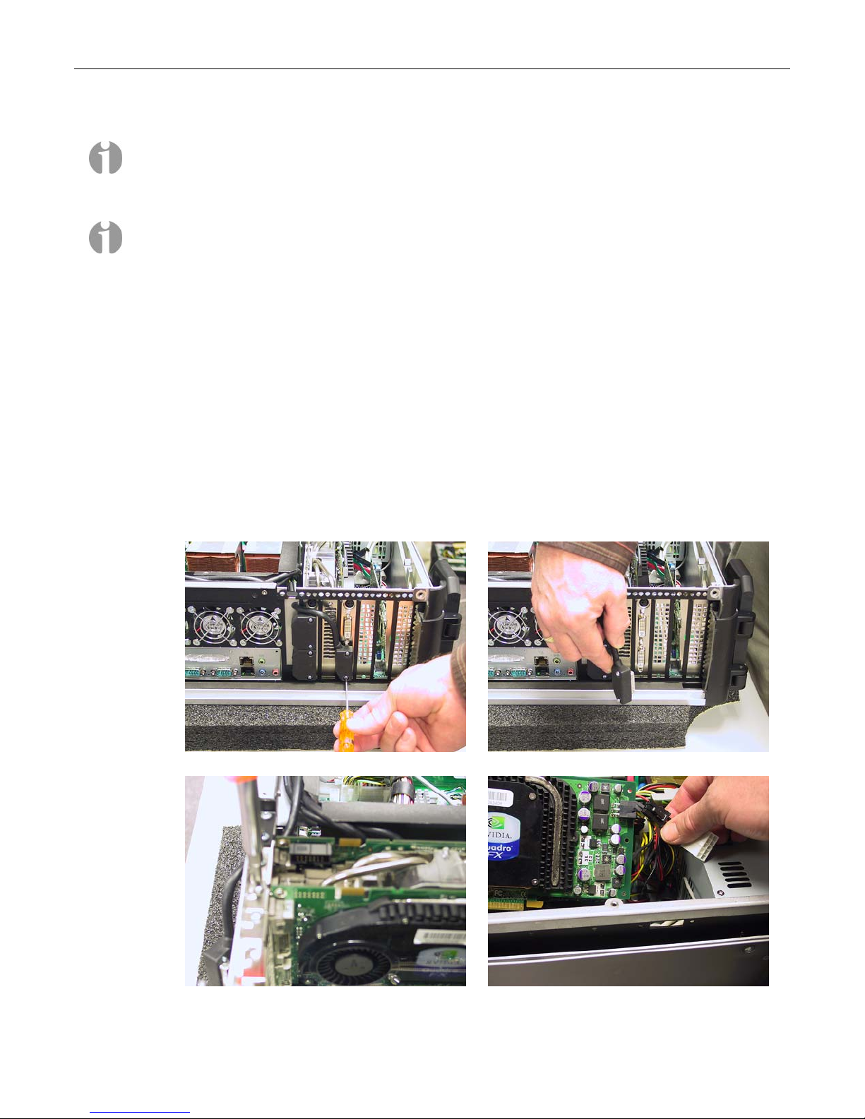
54 MaxPac Dual/Triple-Screen 8230 XRA2/3-Series User Operation and Maintenance Guide
Note: In the case of these SATA cables, there is no good locking mechanism to ensure that they
remain attached to the card, so MaxVision uses a special adhesive. This adhesive is somewhat
flexible and the connectors can be broken free of the bond by simply pulling the SATA connector
straight out (do not pull on SATA cable itself). Reapply adhesive (provided by MaxVision support)
after reattaching the cables to the new card.
Note: Ensure that the tongue on the new/replacement card’s faceplate lines up with the slot in the
chassis (you may have to bend the tongue slightly in the case of a new card).
PCI Express Card (Secondary card for third screen and
Projector Port)
In the case of a dual-screen MaxPac system, the graphics for both screens will be handled by a
single PCI Express card as discussed in the following topic. By comparison, in the case of a triplescreen system, the center and right-hand screens will be driven by the primary PCI Express card,
while the left-hand screen will be driven by a secondary PCI Express graphics card. The unused port
of this card can also be used as a projector port. This topic discusses the replacement of the
secondary PCI Express graphics card.
1) Open the display assembly into its service position as discussed earlier in this chapter.
2) Use a Phillips #1 screwdriver to remove the screws holding the over-molded DVI video connector
to the secondary PCI Express graphics card (Figure 3-39).
Figure 3-39
Figure 3-40
Figure 3-41
Figure 3-42
Page 61
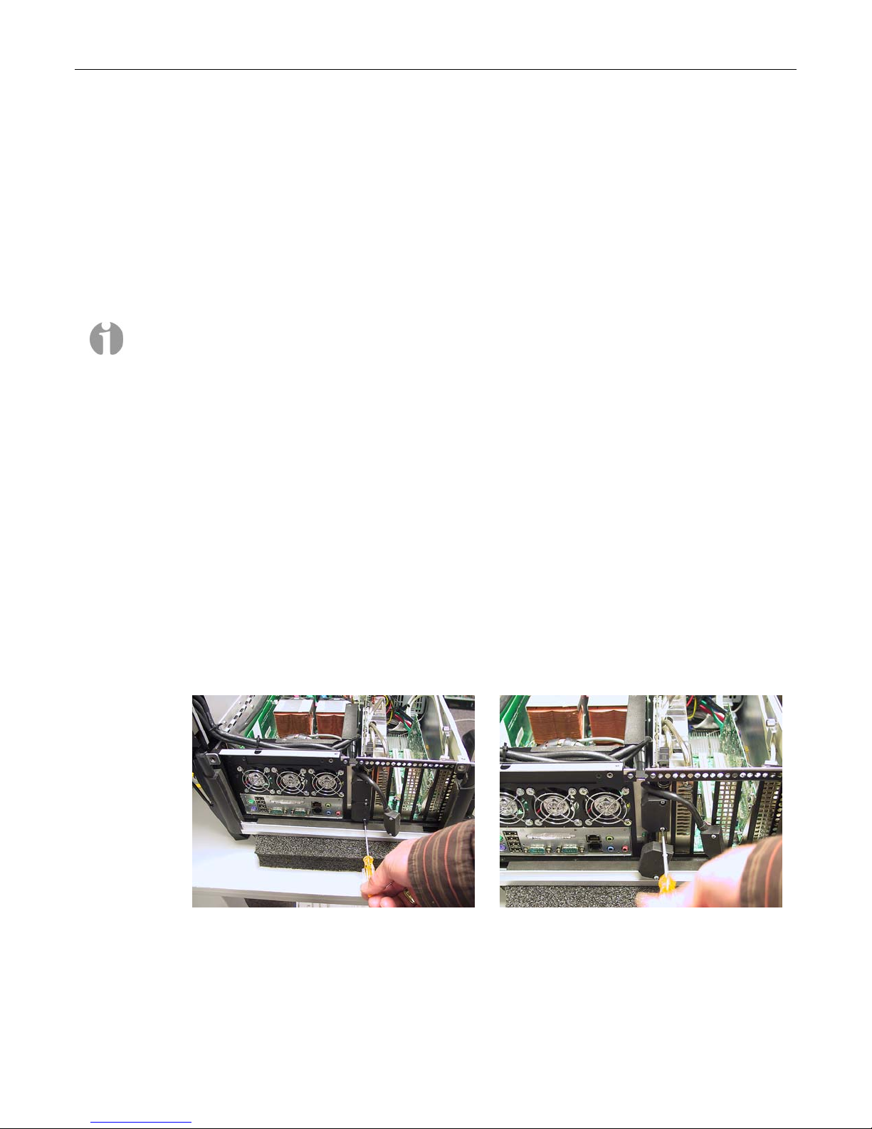
MaxPac Dual/Triple-Screen 8230 XRA2/3-Series User Operation and Maintenance Guide 55
3) Gently disengage the over-molded DVI connector from the secondary PCI Express graphics
board as illustrated in Figure 3-40.
4) Use a Phillips #2 screwdriver to remove the 6-32 screw attaching the card’s retaining bracket to
the inner chassis (Figure 3-41).
5) Some PCI Express cards may have an auxiliary power connector. If so, disconnect it as shown in
Figure 3-42.
6) Gently pull the old card out.
7) Take the new/replacement PCI Express card and incorporate it into the system by performing the
steps described above in reverse order.
Note: Ensure that the tongue on the new/replacement card’s faceplate lines up with the slot in the
chassis (you may have to bend the tongue slightly in the case of a new card).
Note: In this system there is no plastic latch holding the rear of the PCI Express card. The foam
attached to the hinged inner lid of the MaxPac will hold pressure to the back of the card when
properly secured.
PCI Express Card (Primary)
In the case of a dual-screen MaxPac system, the graphics for both screens will be handled by the PCI
Express card located in the primary PCI express slot. By comparison, in the case of a triple-screen
system, the center and right-hand screens will be driven by the PCI Express card located in the
primary slot, while the left-hand screen will be driven by a separate PCI Express graphics card
located in the secondary PCI Express slot. The replacement of the secondary PCI express card was
covered in the previous topic; this topic discusses the replacement of the primary PCI Express card.
1) Open the display assembly into its service position as discussed earlier in this chapter.
2) Use a Phillips #1 screwdriver to remove the screws holding the over-molded video cables to the
primary PCI Express graphics card and gently disengage the over-molded DVI connector from
the card (Figures 3-43 and 3-44).
Figure 3-43
Figure 3-44
Page 62
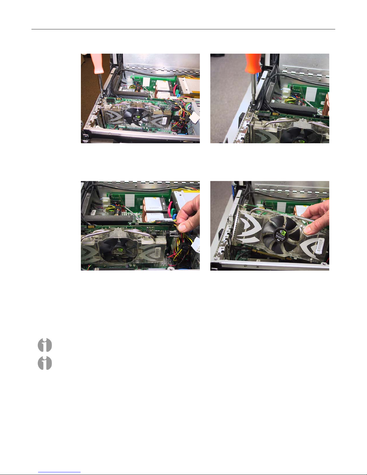
56 MaxPac Dual/Triple-Screen 8230 XRA2/3-Series User Operation and Maintenance Guide
Figure 3-45
Figure 3-46
3) Use a Phillips #2 screwdriver to remove the two 6-32 screws attaching the card’s retaining
bracket – and the special linking bracket – to the inner chassis (Figure 3-45 and 3-46).
Figure 3-47
Figure 3-48
4) Gently remove the special linking bracket and store it somewhere safe.
5) Some PCI Express cards may have an auxiliary power connector. If so, disconnect it as shown
in Figure 3-47.
6) Take the new PCI Express card and incorporate it into the system by performing the steps
described above in reverse order.
Note: Ensure that the tongue on the new/replacement card’s faceplate lines up with the slot in the
chassis (you may have to bend the tongue slightly in the case of a new card).
Note: When removing the video cables, keep track of the order of the connections to the PCI
Express card. The right-hand display is connected to the top connector and the center display is
connected to the bottom connector of the primary PCI Express card. In the case of a triple-display
system, the left display connector (which is a different shape to the other two) is attached to the
bottom DVII connector of the secondary PCI Express graphics board.
Note: In this system there is no plastic latch holding the rear of the PCI Express card. The foam
attached to the hinged inner lid of the MaxPac will hold pressure to the back of the card when
properly secured
Page 63
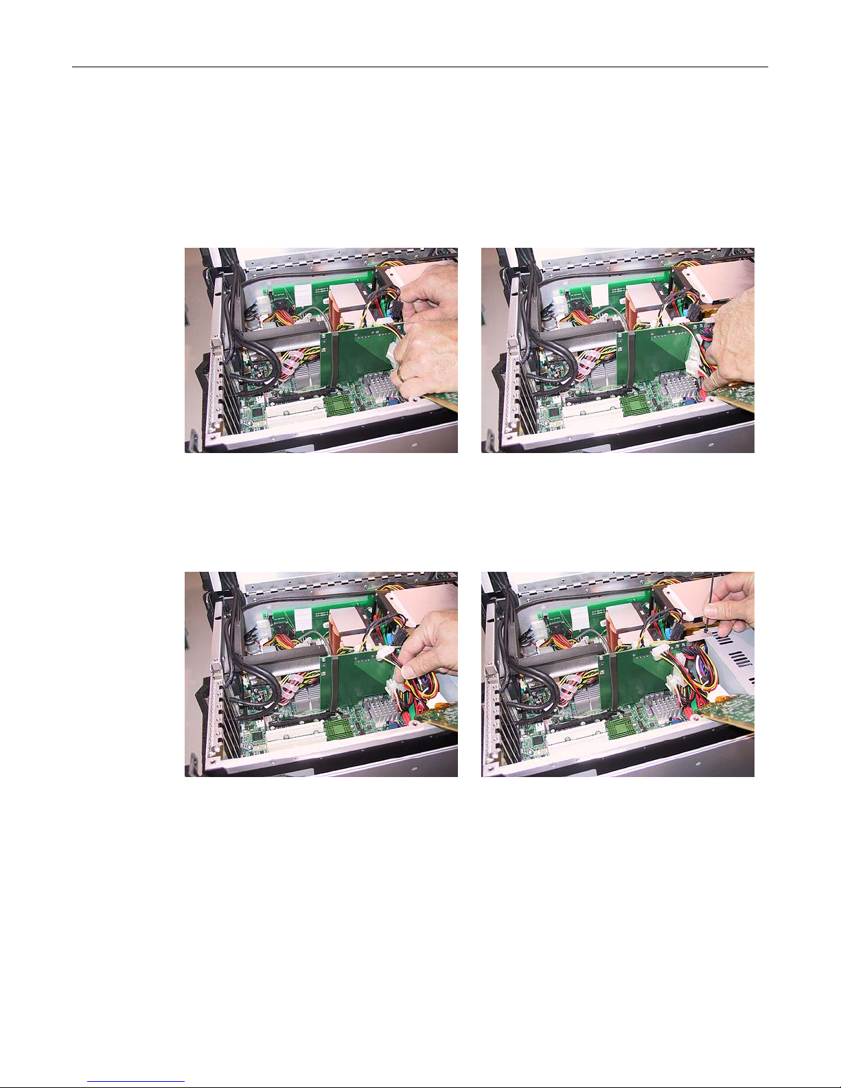
MaxPac Dual/Triple-Screen 8230 XRA2/3-Series User Operation and Maintenance Guide 57
Auxiliary Power Distribution Assembly
Note that the following procedure may be facilitated by first removing the PCI and PCI Express cards
as discussed earlier in this chapter; however, removing these cards is not obligatory.
1) Open the display assembly into its service position as discussed earlier in this chapter.
2) Unplug the top power input connector from the auxiliary power distribution board (Figure 3-49).
Figure 3-49
3) Unplug the bottom power input connector from the auxiliary power distribution board as illustrated
in Figure 3-50.
4) Unplug the CD/DVD power output connector from the auxiliary power distribution board as
illustrated in Figure 3-51.
Figure 3-51
5) Use an Allen key/tool to remove the screw attaching the auxiliary power distribution assembly to
the power supply unit (Figure 3-52).
Figure 3-50
Figure 3-52
6) Use a Phillips #1 screwdriver to remove the two 4-40 screws attaching the auxiliary power
distribution assembly to the side of the inner chassis (Figures 3-53).
Page 64
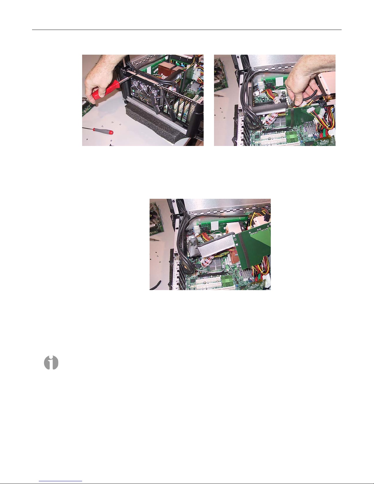
58 MaxPac Dual/Triple-Screen 8230 XRA2/3-Series User Operation and Maintenance Guide
Figure 3-53
7) Cut the cable tie holding the main motherboard power cable (so as to keep it out of the way) as
illustrated in Figure 3-54.
8) Gently lift the auxiliary power distribution assembly up and away from the inner chassis
(Figure 3-55).
Figure 3-55
9) Take the new auxiliary power distribution assembly supplied by MaxVision support and
incorporate it into the system by performing the steps described above in reverse order.
Figure 3-54
Main Power Distribution Board
Note: Return the system to MaxVision as described in Appendix D. Do not attempt to replace the
main power distribution board in the field unless you have been trained and certified for such a
procedure.
Hard Drive Magazine (also Individual Hard Drives)
1) Undo the knurled screw holding the middle binding bar (Figure 3-56) and then remove the binding
bar (Figure 3-57).
Page 65
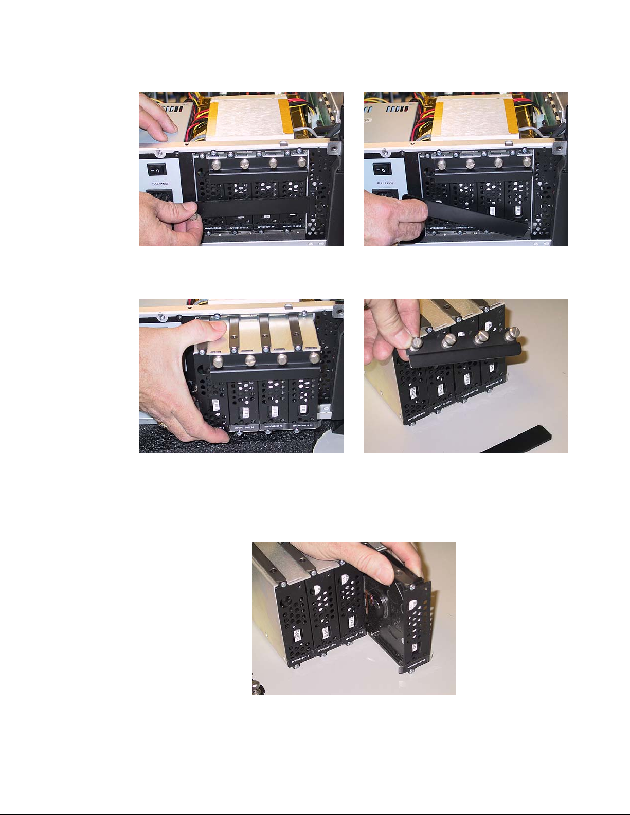
MaxPac Dual/Triple-Screen 8230 XRA2/3-Series User Operation and Maintenance Guide 59
Figure 3-56
Figure 3-57
2) Gently pull on the magazine handle to extract the magazine from the inner chassis (Figure 3-58).
Figure 3-58
Figure 3-59
3) In order to replace an individual drive, turn each of the four knurled screws attached to the upper
binding bar until they pop out and then remove the upper binding bar (Figure 3-59). Note that the
upper binding bar has tabs that are inserted into slots of the main drive cage.
4) Gently grasp the drive in question and pull it out of the magazine (Figure 3-60).
Figure 3-60
Page 66
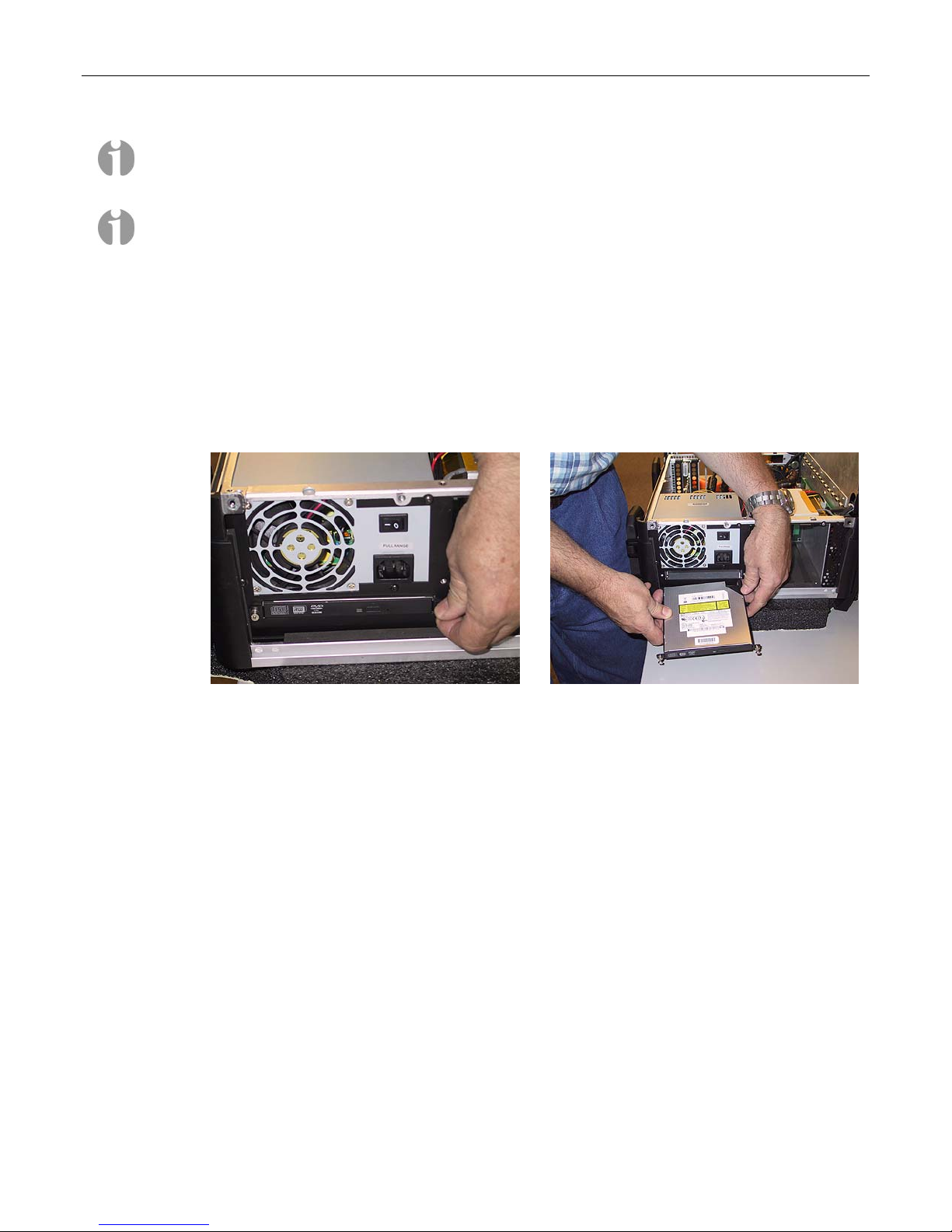
60 MaxPac Dual/Triple-Screen 8230 XRA2/3-Series User Operation and Maintenance Guide
Note: These disks are hot-swappable, so you can replace individual drives while the magazine remains
resident in the system. When the upper binding bar is removed, the four slots in the main drive cage
may slide back. Make sure that when replacing the upper binding bar that the tabs go into these slots.
Note: In order to easily identify these disks, MaxVision serial numbers are affixed to the bottom edge
(the small white strips shown toward the bottom of the drives in Figure 3-57). It is recommended that
you record the positions and serial numbers of your disks for each MaxPac (especially when you are
actually replacing individual disks).
Optical Drive (CD/DVD)
1) Note that it is not necessary to open the display assembly into its service position in order to
perform this procedure.
2) Undo the two knurled attaching the CD/DVD drive to the outside of the system's main chassis
(Figure 3-61).
Figure 3-61
3) Gently remove the CD/DVD drive from the system (Figure 3-62).
4) Take the new CD/DVD assembly as supplied by MaxVision support and incorporate it into the
system by performing the steps described above in reverse order.
Optical Drive (CD/DVD) Backplane
1) Open the display assembly into its service position as discussed earlier in this chapter.
2) Remove the CD/DVD drive as discussed in the previous topic.
3) Remove the ATA cable (observing where the red stripe is for future reference) as illustrated in
Figure 3-63.
Figure 3-62
Page 67
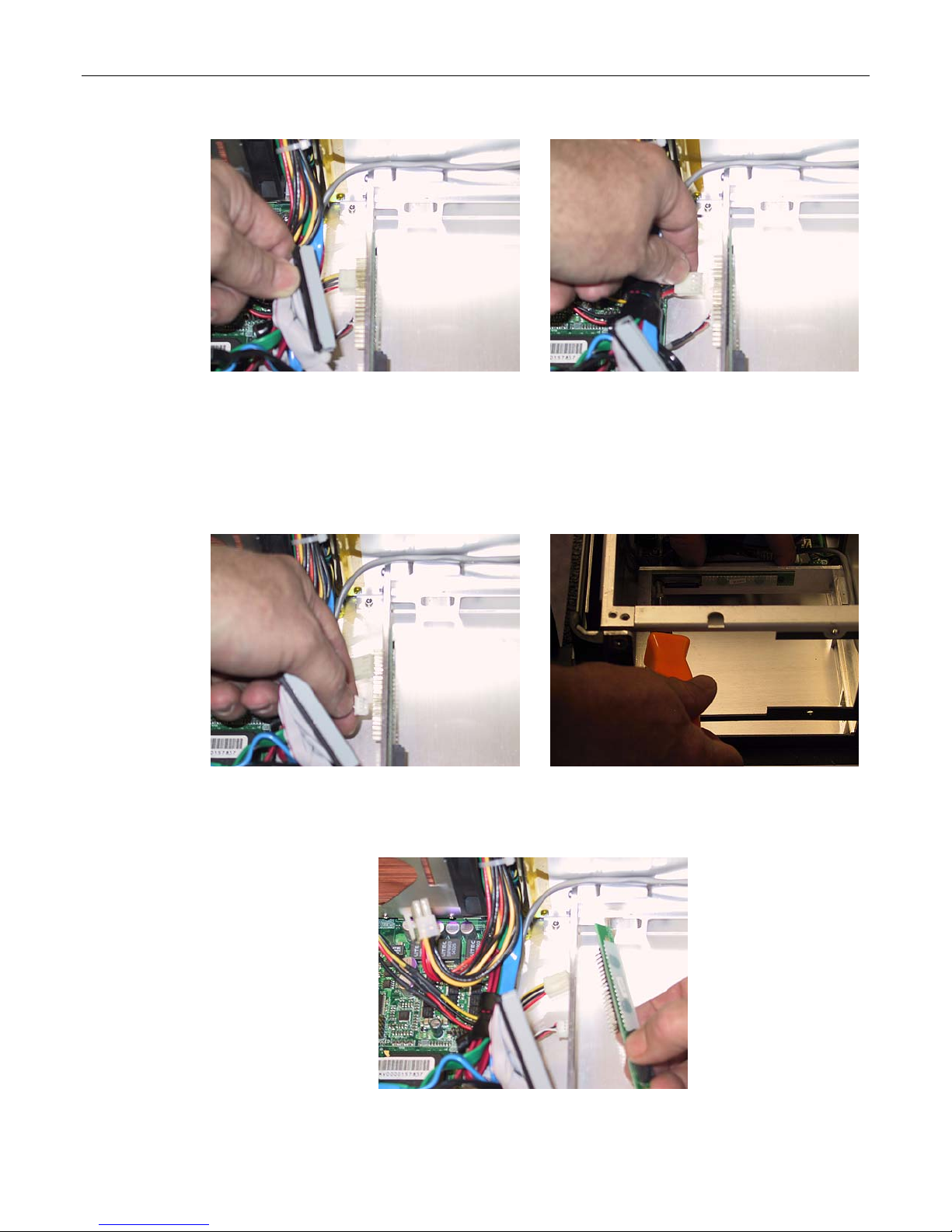
MaxPac Dual/Triple-Screen 8230 XRA2/3-Series User Operation and Maintenance Guide 61
Figure 3-63
Figure 3-64
4) Remove the main power connector as illustrated in Figure 3-64 (release the latch with your finger
or thumb nail while pulling ion the cable).
5) Remove the CD/Audio cable as illustrated in Figure 3-65.
6) Use a Philips #1 screwdriver to remove the two screws attaching the CD/DVD backplane to the
main chassis as illustrated in Figure 3-66.
Figure 3-65
Figure 3-66
7) Gently remove the CD/DVD backplane as illustrated in Figure 3-67.
Figure 3-67
Page 68
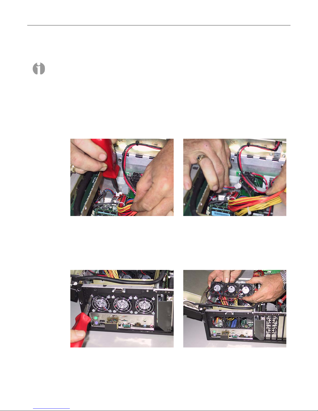
62 MaxPac Dual/Triple-Screen 8230 XRA2/3-Series User Operation and Maintenance Guide
8) Present the replacement CD/DVD backplane supplied by MaxVision support to the inner
chassis and perform the steps described above in reverse order.
Note: If the replacement CD/DVD backplane does not come equipped with a protective
(insulating) Mylar cover, remove this piece from your original backplane and reattach it to the
new backplane.
External Cooling Fan Assembly
1) Open the display assembly into its service position as discussed earlier in this chapter.
2) Disconnect the external cooling fan assembly’s power supply cable from the main distribution
board. The connector is shown as being pointed to by a screwdriver in Figure 3-68, but you
should simply pull it away using your fingers as shown in Figure 3-69.
Figure 3-68
3) All three fans must be treated as a single assembly, so remove the twelve self-tapping Plastite
screws (4 per fan) attaching the fans to the internal chassis (Figure 3-70) and then gently lift the
fan assembly away from the inner chassis (Figure 3-71).
4) Present the replacement fan assembly supplied by MaxVision support to the inner chassis and
perform the steps described above in reverse order.
Figure 3-70
Figure 3-69
Figure 3-71
Page 69
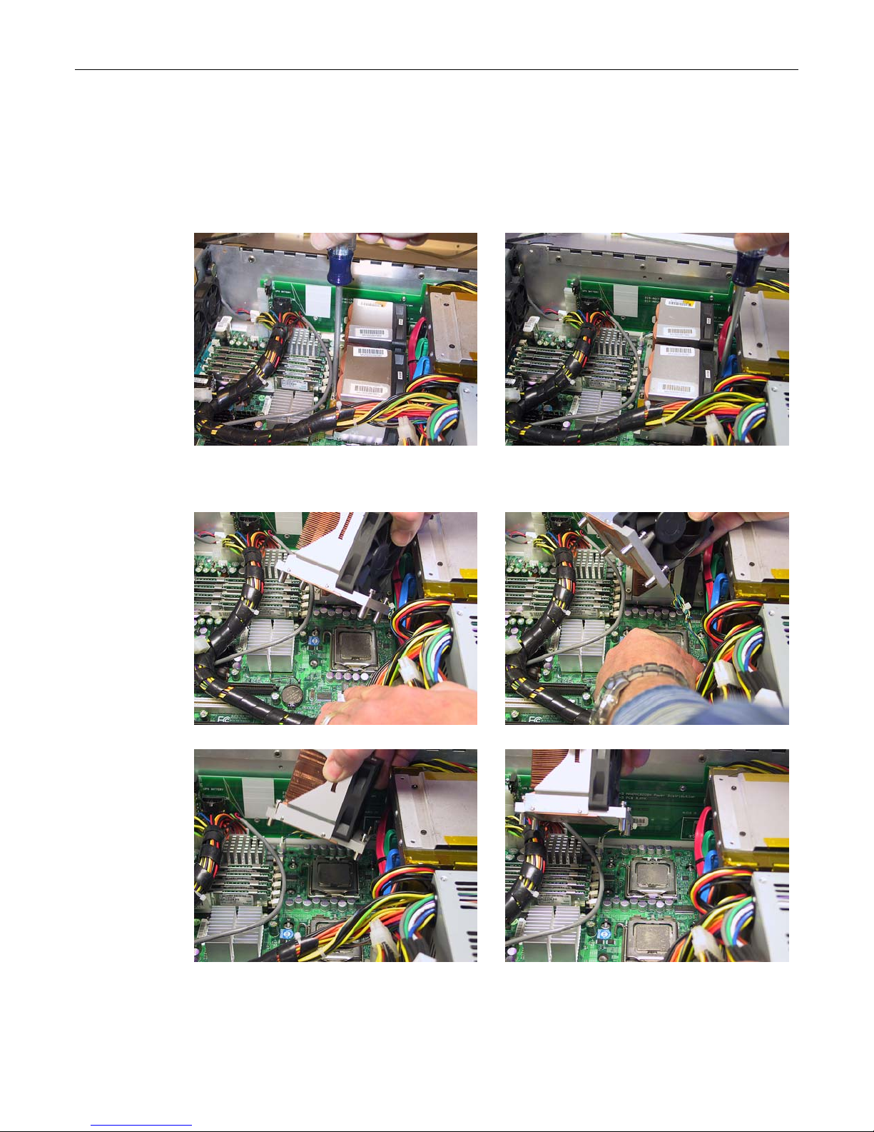
MaxPac Dual/Triple-Screen 8230 XRA2/3-Series User Operation and Maintenance Guide 63
CPU Cooling Fans
1) Open the display assembly into its service position as discussed earlier in this chapter.
2) There are two screws on either side of the cooling fan assembly. Use a Phillips #2 screwdriver to
loosen these captured screws (Figures 3-72 and 3-73).
Figure 3-72
3) Gently lift the cooling fan assembly away from the chassis as illustrated in Figure 3-74.
Figure 3-74
Figure 3-73
Figure 3-75
4) Each fan has its own power connector that is attached to the main motherboard. Disconnect the
power connector associated with the failed fan (Figure 3-75).
Figure 3-76
Figure 3-77
Page 70
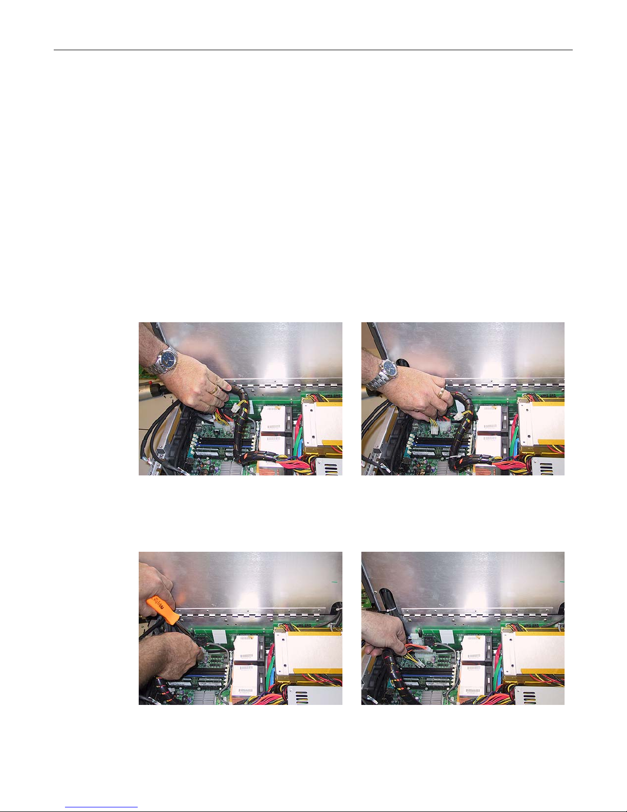
64 MaxPac Dual/Triple-Screen 8230 XRA2/3-Series User Operation and Maintenance Guide
5) Figures 3-76 and 3-77 illustrate the removal of the 2
6) Present the replacement fan assembly supplied by MaxVision support to the CPU and perform
the steps described above in reverse order. Ensure the fan assembly in screwed in with equal
pressure on all side and the fan power connector is replaced prior to powering up the system to
avoid CPU damage.
Main Power Supply Unit (PSU)
Depending on the problem you are experiencing – and as directed by MaxVision support – you may
need to replace the entire power supply as discussed below.
1) Open the display assembly into its service position as discussed earlier in this chapter.
2) Remove the video distribution board as discussed earlier in this chapter.
3) Disconnect the EPS12V 8-pin (4 x 2) power connector from the motherboard. Pull the connector
up while using a flat-blade screwdriver to push the top of the release catch (facing the interior of
the chassis) into the body of the connector (Figures 3-78 and 3-79).
nd
CPU Fan Assembly.
Figure 3-78
4) Disconnect the ATX 24-pin power connector from the motherboard. Pull the connector up while
using a flat-blade screwdriver to push the top of the release catch (facing the bottom of the
chassis) into the body of the connector (Figures 3-80 and 3-81).
Figure 3-80
Figure 3-79
Figure 3-81
Page 71
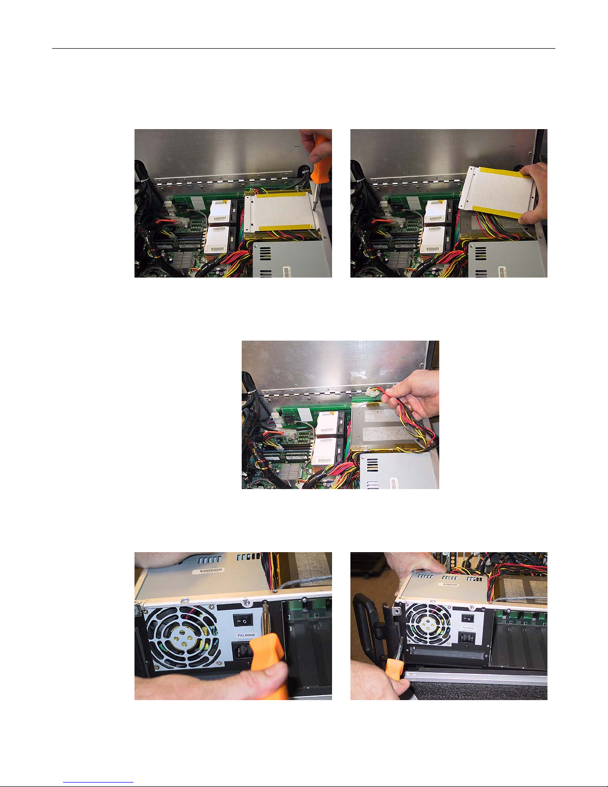
MaxPac Dual/Triple-Screen 8230 XRA2/3-Series User Operation and Maintenance Guide 65
5) Use a Phillips #1 screwdriver to remove the three 4-40 screws holding the wire harness
protector plate (Figure 3-82), then gently remove the protector plate to expose the wire
harness (Figure 3-83).
Figure 3-82
Figure 3-83
6) Disconnect the power connector to the main distribution board – make sure to use the
connector's release catch (Figure 3-84).
Figure 3-84
7) Use a Phillips #2 screwdriver to remove the four screws attaching the power supply unit to the
side of the inner chassis (Figures 3-85 through 3-88).
Figure 3-85
Figure 3-86
Page 72
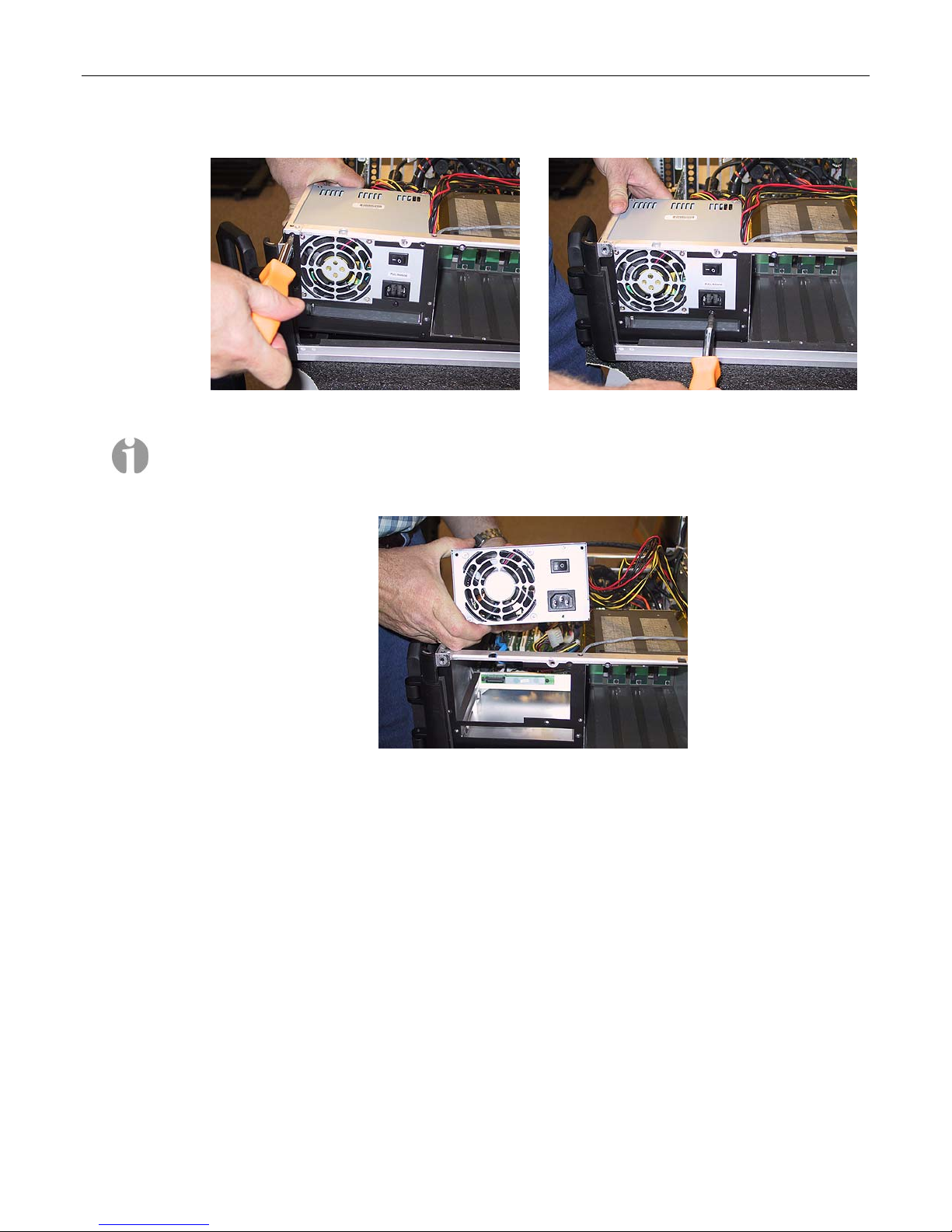
66 MaxPac Dual/Triple-Screen 8230 XRA2/3-Series User Operation and Maintenance Guide
Figure 3-87
Note: Observe the way in which the inner chassis is lifted in Figures 3-86 and 3-87 so as to
facilitate access to two of these screws.
8) Gently lift the power supply out of the system as illustrated in Figure 3-89.
Figure 3-89
9) Take the new main power supply unit supplied by MaxVision support and incorporate it into the
system by performing the steps described above in reverse order.
Figure 3-88
Motherboard
Replacing the motherboard is non-trivial. It is easy to damage the motherboard unless one has the
appropriate tools and training. For this reason, you must either return the MaxPac system to
MaxVision or be factory trained by MaxVision personnel (see Appendix D for more details about
contacting MaxVision support and returning your MaxPac to MaxVision).
1) Open the display assembly into its service position as discussed earlier in this chapter.
2) Remove any PCI and PCI Express cards as discussed earlier in this chapter.
3) Remove the Video Distribution Board as detailed earlier in this chapter.
4) In order to replace the motherboard, you must first remove the inner chassis, and in order to do
this the display power cables must be disconnected from the power distribution board. Figures 90
Page 73
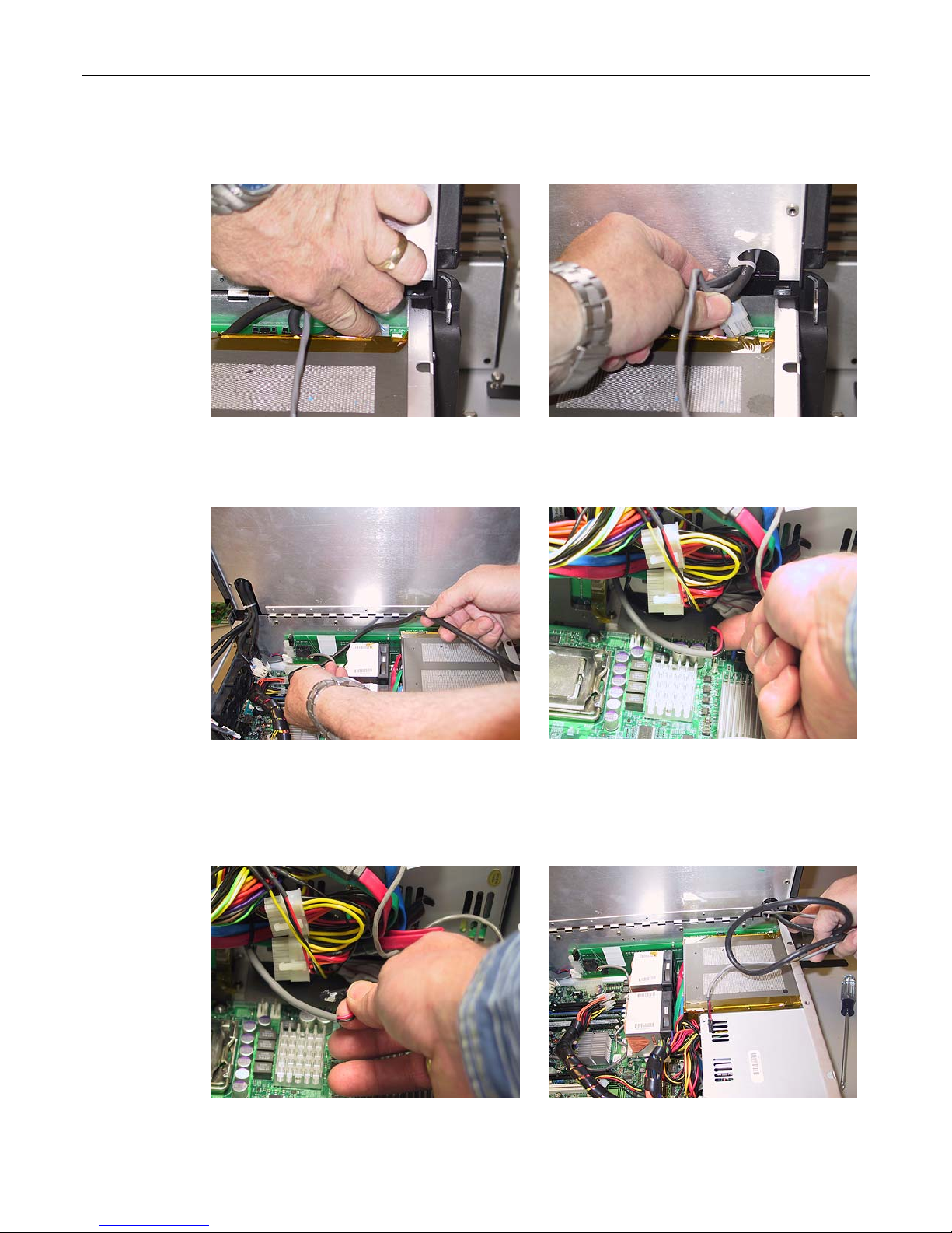
MaxPac Dual/Triple-Screen 8230 XRA2/3-Series User Operation and Maintenance Guide 67
and 91 show the left-hand display power cable being disconnected; repeat this procedure for the
right-hand display.
Figure 3-90
Figure 3-91
5) The right monitor data cable must be carefully removed from between the hard disk cage, the
CPU heatsink/fan assembly, and the power distribution board as shown in figure 3-92
Figure 3-92
Figure 3-93
6) The soft power cable must be removed from the motherboard connection posts (the location of
this connector is pointed out in Figure 3-93). Observe that this cable connector is attached to the
motherboard with a flexible adhesive (such as Marine Goop). Simply pull the connector (not the
wire) until the adhesive gives (Figure 3-94).
Figure 3-94
Figure 3-95
Page 74
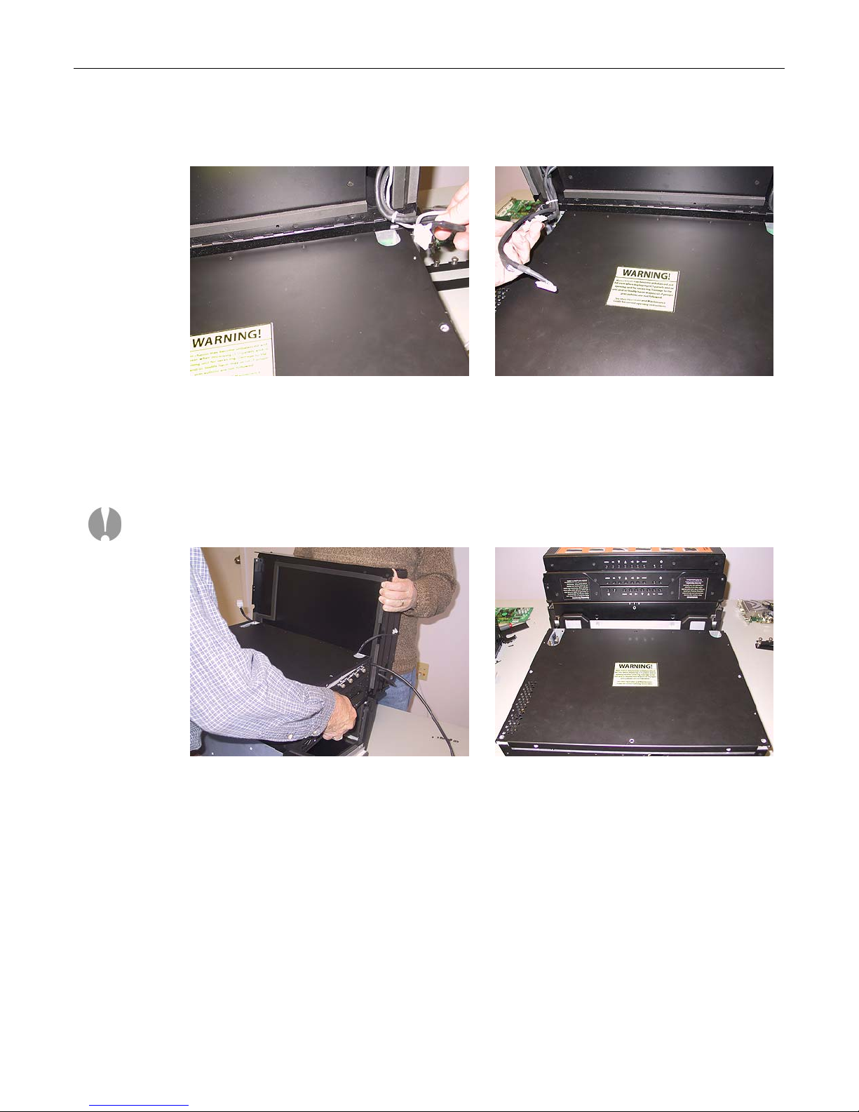
68 MaxPac Dual/Triple-Screen 8230 XRA2/3-Series User Operation and Maintenance Guide
7) The power and video cables for the right monitor (and also and the soft power cable) must be
removed from the inner chassis cover cable channel as shown in Figures 3-95 and 3-96.
Figure 3-96
Figure 3-97
8) The center and left monitor power and video cables must be removed from the inner chassis
cover cable channel as show in Figure 3-97
9) You will need a second person to hold the monitor assembly while you lift the inner chassis out of
the outer chassis Figure 3-98.
Note: As the weight of the inner chassis is removed, the display assembly and outer chassis will
topple over if not being held securely.
Figure 3-98
Figure 3-99
10) Next, the display assembly should be rotated down as illustrated in Figure 3-99.
11) Now, tilt the alluminum inner chassis lid into a vertical orientation so as to facititate access to the
motherboard. There are two screws on either side of the cooling fan assembly. Use a Phillips #2
screwdriver to loosen these captured screws (Figures 3-100 and 3-101).
Page 75
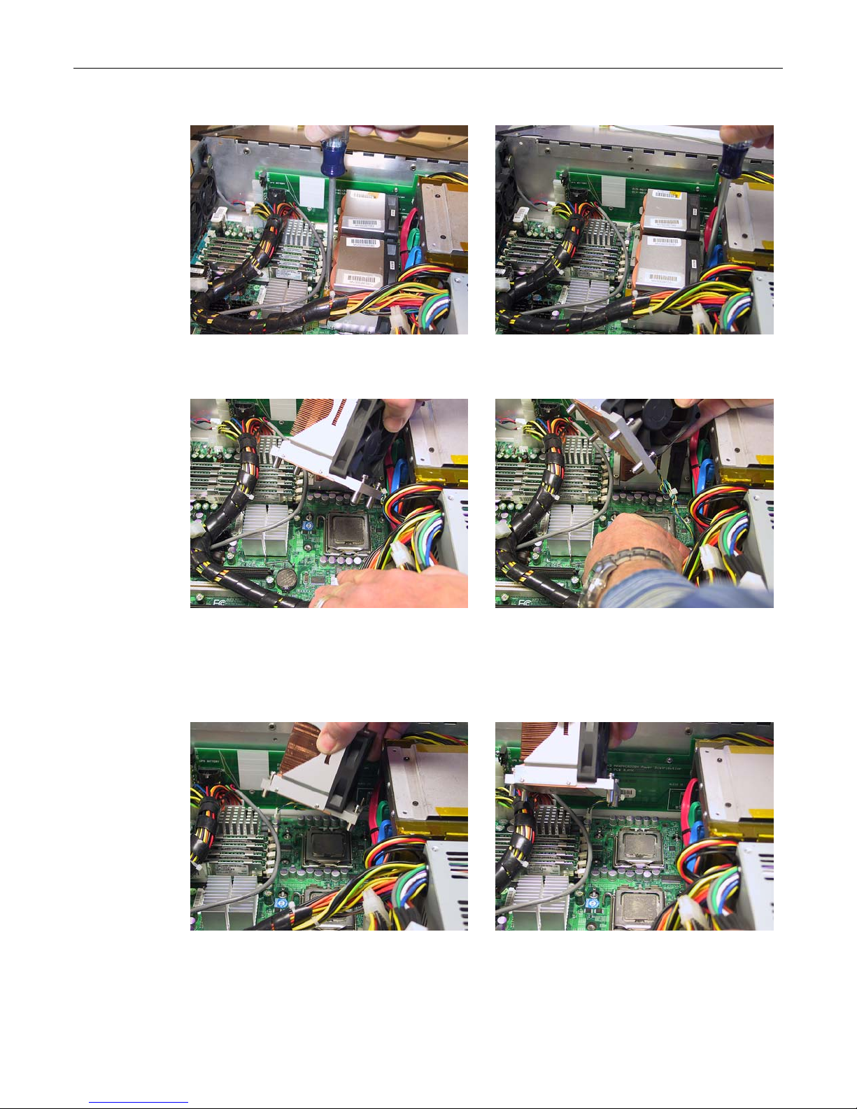
MaxPac Dual/Triple-Screen 8230 XRA2/3-Series User Operation and Maintenance Guide 69
Figure 3-100
Figure 3-101
12) Gently lift the cooling fan assembly away from the chassis as illustrated in Figure 3-102.
Figure 3-102
Figure 3-103
13) Each fan has its own power connector that is attached to the main motherboard. Disconnect the
power connector associated with the CPU fan (Figure 3-103).
14) Figures 3-104 and 3-105 illustrate the removal of the second CPU fan assembly.
Figure 3-104
15) The motherboard shadow box must be removed in order to slide out the motherboard. Remove
the screws from each side of the shadow box as shown in Figures 3-106 through 3-108.
Figure 3-105
Page 76
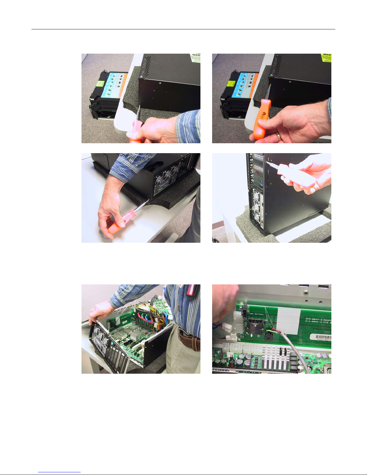
70 MaxPac Dual/Triple-Screen 8230 XRA2/3-Series User Operation and Maintenance Guide
Figure 3-106
Figure 3-107
Figure 3-108
Figure 3-109
16) Remove the screws from the bottom of the shadow box as shown in Figure 3-109, then
carefully remove the shadow box, fan power and speaker connection as shown in Figures
3-110 through 3-112.
Figure 3-110
Figure 3-111
Page 77
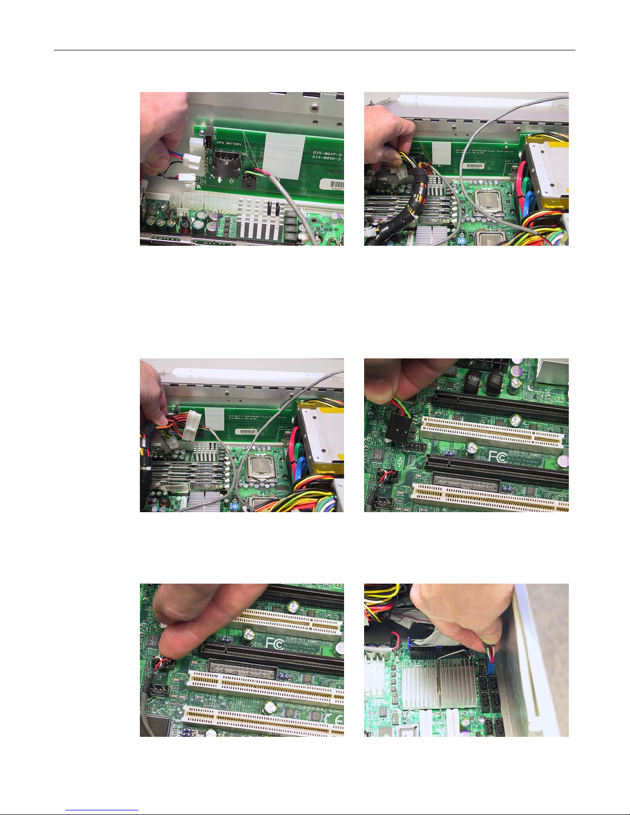
MaxPac Dual/Triple-Screen 8230 XRA2/3-Series User Operation and Maintenance Guide 71
Figure 3-112
Figure 3-113
17) Disconnect the EPS12V 8-pin (4 x 2) power connector from the motherboard. Pull the
connector up while using a flat-blade screwdriver to push the top of the release catch (facing
the interior of the chassis) into the body of the connector (Figures 3-113).
18) Disconnect the ATX 24-pin power connector from the motherboard. Pull the connector up
while using a flat-blade screwdriver to push the top of the release catch (facing the bottom of
the chassis) into the body of the connector (Figures 3-114).
Figure 3-114
Figure 3-115
19) Remove the audio-out cable connecting the motherboard to the main power distribution
board (disconnect this cable from the motherboard) as shown in Figure 3-115. Observe the
polarity of this connection.
Figure 3-116
Figure 3-117
Page 78
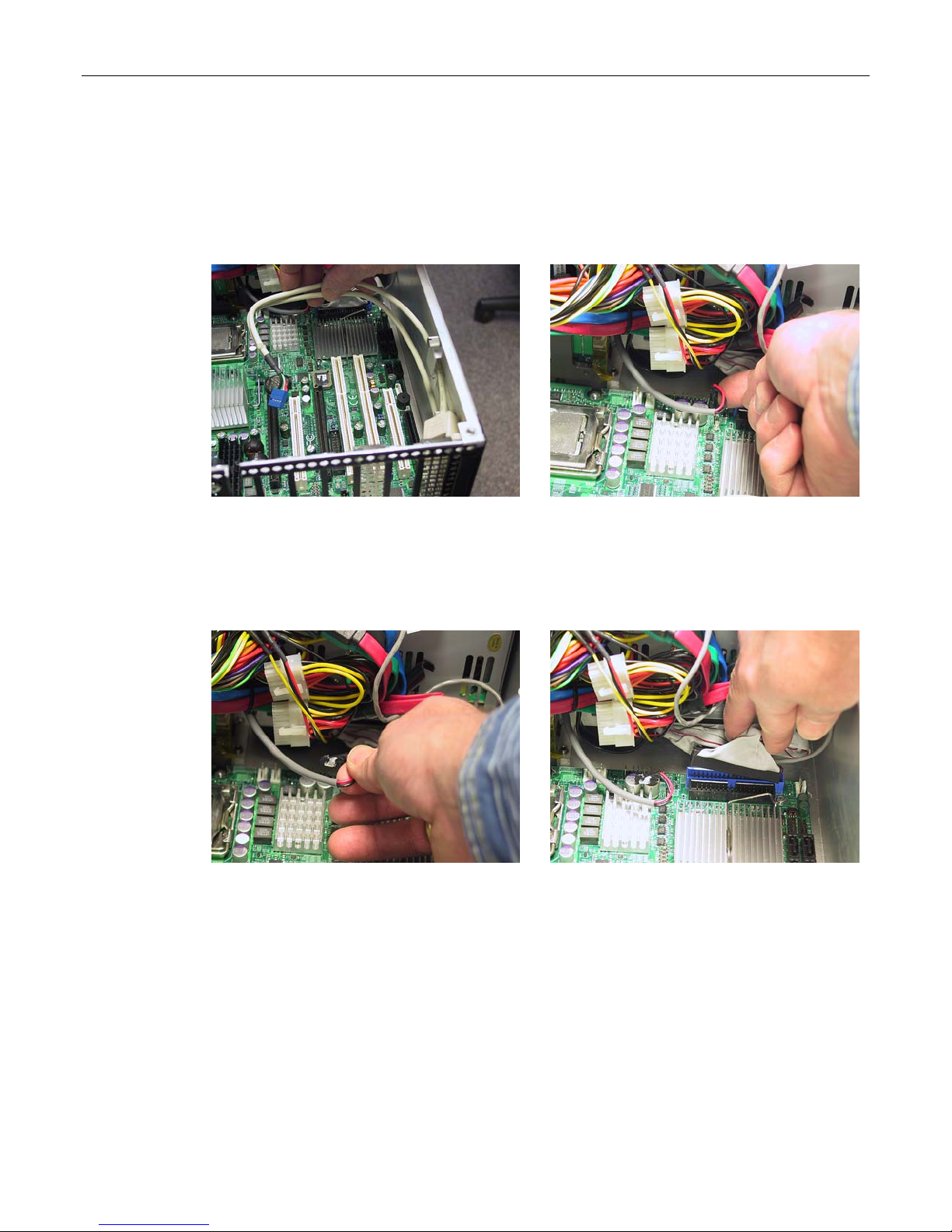
72 MaxPac Dual/Triple-Screen 8230 XRA2/3-Series User Operation and Maintenance Guide
20) Remove the CD Audio In cable from the motherboard as illustrated in Figure 3-116
21) Remove the Internal USB cable connection from the motherboard as illustrated in Figures
3-117 and 3-118. These internal USB cables are normally used for USB Security Devices
common with many applications.
Figure 3-118
Figure 3-119
22) The soft power cable must be removed from the motherboard connection posts (the location
of this connector is pointed out in Figure 3-119). Observe that this cable connector is
attached to the motherboard with a flexible adhesive (such as Marine Goop). Simply pull the
connector (not the wire) until the adhesive gives as illustrated in Figure 3-120.
Figure 3-120
Figure 3-121
23) Remove the DVD ATA cable connecting to the ATA port of the motherboard as shown in
Figure 3-121.
24) Remove the screws securing the motherboard to the inner chassis assembly as shown in
Figures 3-122 and 3-123.
Page 79
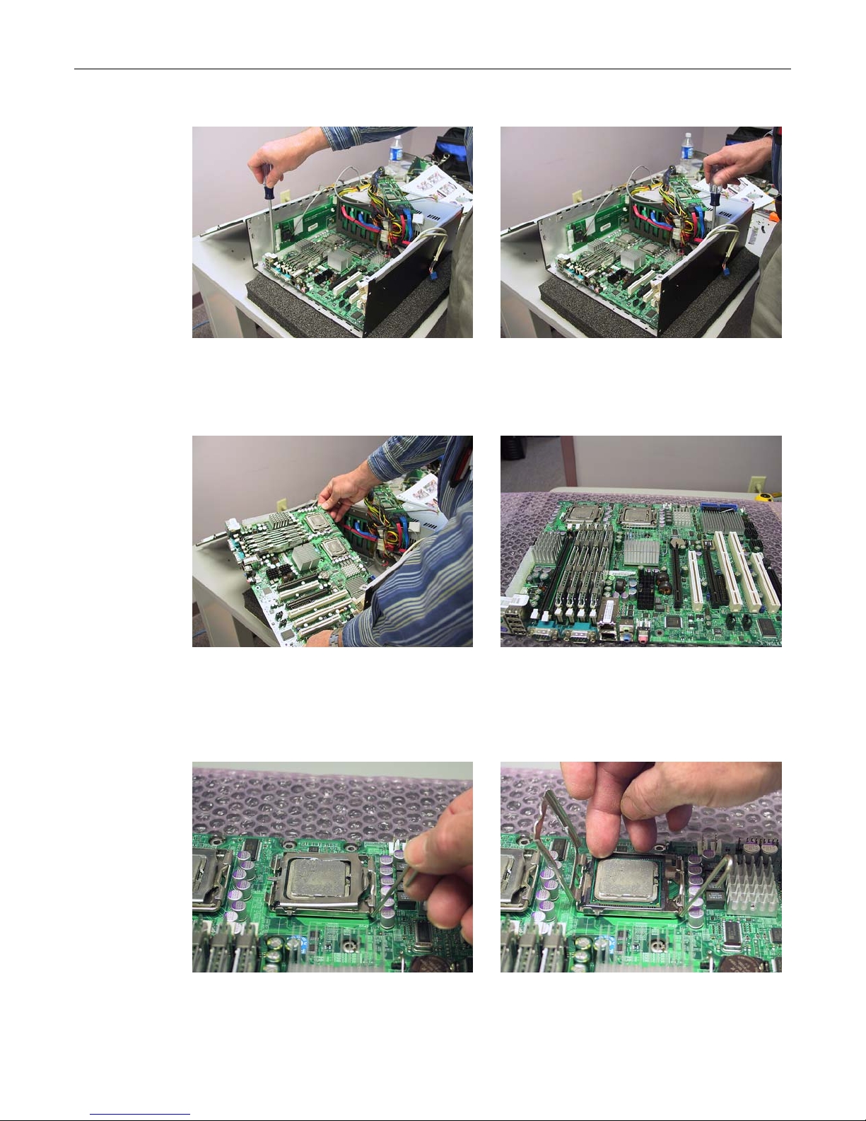
MaxPac Dual/Triple-Screen 8230 XRA2/3-Series User Operation and Maintenance Guide 73
Figure 3-122
Figure 3-123
25) Now slide the motherboard out and place on a protected surface as shown in Figures 3-124
and 3-125.
Figure 3-124
Figure 3-125
26) Under the direction of MaxVision support carefully remove the XEON series 5100 CPU
from its socket as illustrated in Figures 3-126 through 3-128. Observe the keying of the
CPU into its socket.
Figure 3-126
Figure 3-127
Page 80
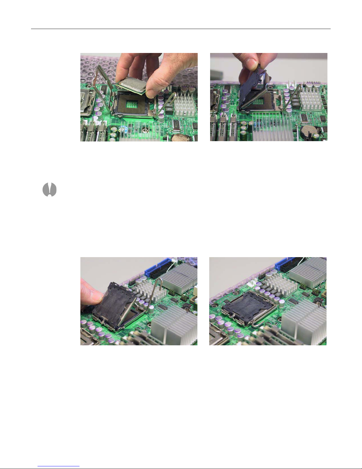
74 MaxPac Dual/Triple-Screen 8230 XRA2/3-Series User Operation and Maintenance Guide
Figure 3-128
Figure 3-129
27) Observe that the CPU sockets on the new motherboard have protective covers; gently
remove these covers.
Note: EXTREME CARE must be taken not to damage in any way the delicate pins used
in the CPU sockets on both the replacement motherboard AND the original (suspect)
motherboard. Once bent, these pins cannot be straightened resulting in the total loss of
the motherboard. These motherboards are valued at approximately $500 and this type of
damage is not covered under the MaxVision warranty.
Thus, once you've removed the protective CPU pin covers from the new motherboard,
immediately install them onto the suspect or bad motherboard before any additional
handling of either motherboard. The installation of one of the pin protectors is illustrated
in Figures 3-129, 3-130, and 3-131.
Figure 3-130
Observe that there is a hinged metal lid attached to the CPU socket. This lid should be raised
to a 45º angle (Figure 3-129) and the protective cover should be attached to the lid.
This requires a somewhat involved process. There are two "hooks" approximately ¼-inch apart
at one side of the protective cover. These hooks engage either side of a small flange on the
metal lid at the side of the hinge attached to the socket on the motherboard (Figure 3-129).
At the opposite side of the protective cover there are two small "posts" – one in either corner.
The protective cover should be pressed into place such that these posts engage with the
edge of the hinged metal lid that is farthest from the motherboard (Figure 3-130).
Figure 3-131
Page 81

MaxPac Dual/Triple-Screen 8230 XRA2/3-Series User Operation and Maintenance Guide 75
The hinged metal lid should be gently lowered onto the CPU socket (Figure 3-131). Finally,
depress the locking lever (shown in its raised/unlocked position in Figures 3-129 and 3-130)
into its lowered/locked position as illustrated in Figure 3-131.
28) Gently attach the XEON CPUs into the replacement motherboard (observing the original
keying), and then insert the replacement motherboard into the inner chassis by
performing the steps above in reverse order.
Page 82

76 MaxPac Dual/Triple-Screen 8230 XRA2/3-Series User Operation and Maintenance Guide
Appendix A: Creating and Using
Backup Images (Including
Restoring Your OS)
Introduction
Every MaxVision system comes equipped with a MaxVision Recovery DVD. In addition to an image of
your operating system, this disc also contains a copy of the Acronis True Image™ application from
Acronis (www.acronis.com). Acronis True Image is a superb tool for operating system (OS)
deployment, software distribution, back-up, and disaster recovery. In particular, this utility allows you
to make reliable backups of your system drives, including applications and critical data. There are two
primary scenarios that need be considered as follows:
Restoring the MaxVision-supplied Image
This is the worst-case scenario. It assumes that your system has undergone some catastrophic
failure such that – under the direction of MaxVision support – you are going to replace your primary
hard drive(s) and/or restore the original MaxVision-supplied image. In this case, you will lose any
applications and data that you have installed, loaded, or created on your main “C:” drive/partition.
Note: If you do re-load the original MaxVision-supplied image, you will also have to re-run the
initialization procedures – including re-activating/re-registering your OS license – as described earlier
in this manual.
Creating Your Own Image
This scenario assumes that you have added new applications, loaded or created new datasets, and
generally configured and customized your MaxVision system the way you like it. At this stage,
before you deploy the system, it is strongly recommended that you use the Acronis True Image
application to create an image of the system. Similarly, as you add additional applications or
generate additional datasets, it is strongly recommended that you create periodic backup images.
This greatly facilitates your ability to return the system to a “known good state” should any problems
arise (such as a virus attack or a hard drive failure) at some stage in the future.
For the purposes of this example, we will assume that you are writing your image to CD media (as
opposed to DVD), and that the image will occupy two CDs.
1) Power-down the system.
2) Ensure that the bootable recovery DVD supplied in the accessory pack is in the system's
CD/DVD drive. In the case of a multiple DVD image, ensure Disk #1 is in the drive.
3) Power-up the system. This will automatically launch the Acronis application as shown in Figure A-1.
Page 83
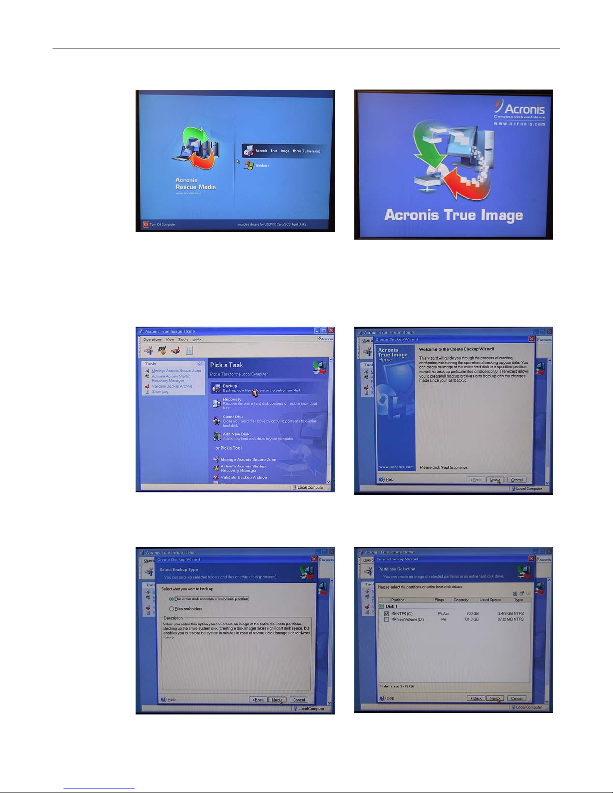
MaxPac Dual/Triple-Screen 8230 XRA2/3-Series User Operation and Maintenance Guide 77
Figure A-1
Figure A-2
4) Use the mouse to select the Acronis item as shown in Figure A-1.
5) Following the splash screen (Figure A-2), under the Pick a Task heading, select the Backup option
(the top item) as illustrated in Figure A-3.
Figure A-3
Figure A-4
6) Follow the actions depicted by the screenshots shown in Figures A-4 through A-18.
Figure A-5
Figure A-6
Page 84
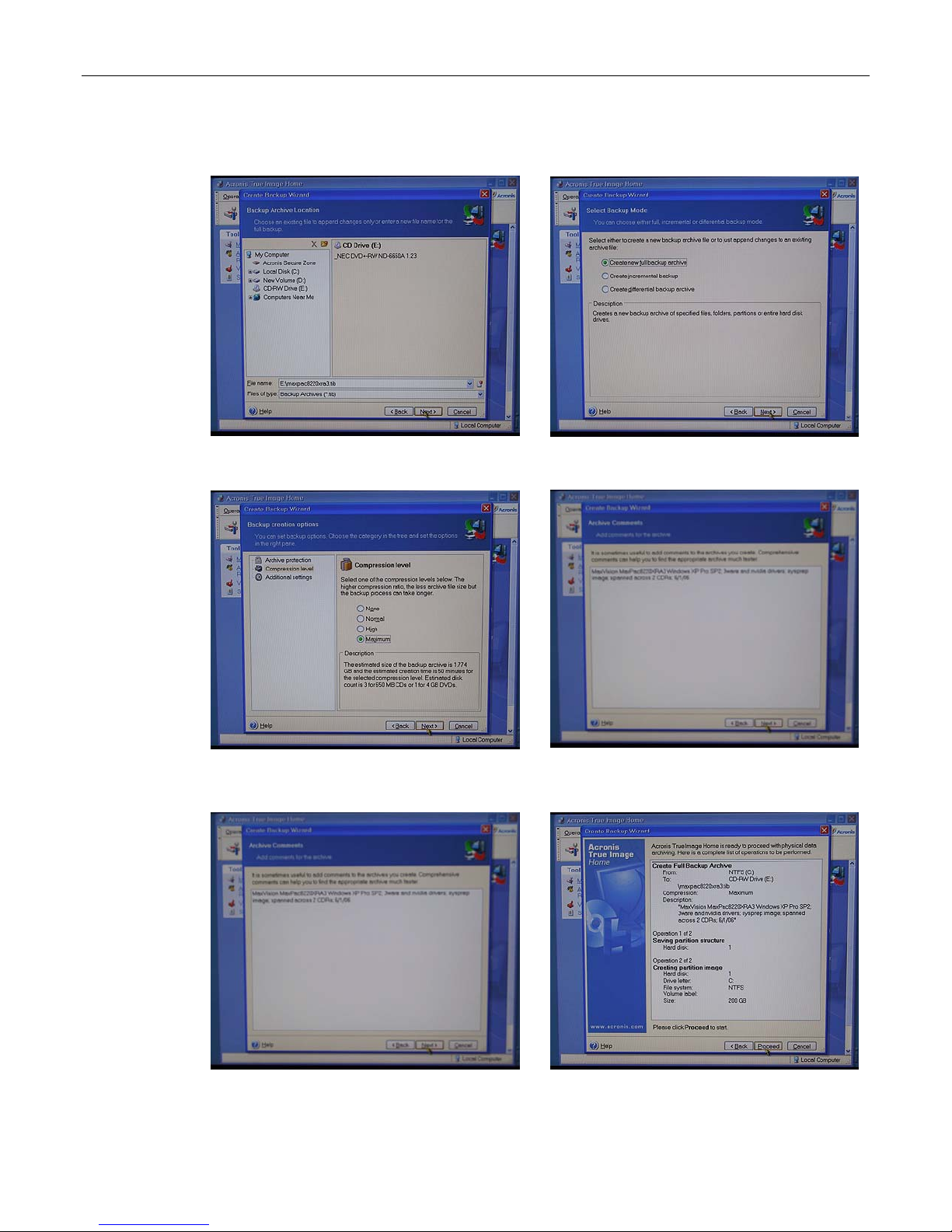
78 MaxPac Dual/Triple-Screen 8230 XRA2/3-Series User Operation and Maintenance Guide
Figure A-7
Figure A-8
Figure A-9
Figure A-10
Figure A-11
Figure A-12
Page 85
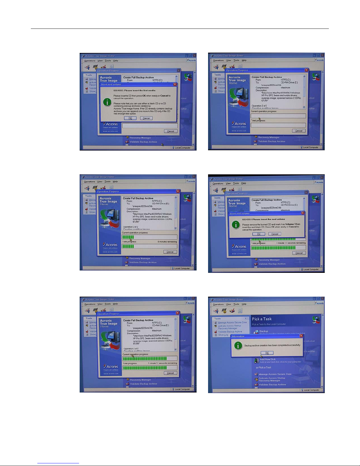
MaxPac Dual/Triple-Screen 8230 XRA2/3-Series User Operation and Maintenance Guide 79
Figure A-13
Figure A-14
Figure A-15
Figure A-16
Figure A-17
Figure A-18
Page 86
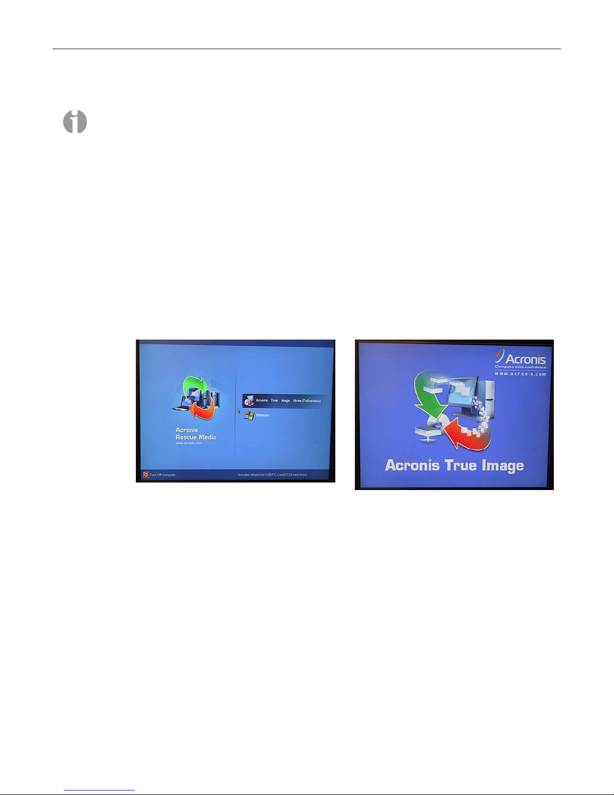
80 MaxPac Dual/Triple-Screen 8230 XRA2/3-Series User Operation and Maintenance Guide
Restoring Your Own Image
Note: If you do re-load an image (containing the OS) that you have created yourself following your
original activation and registration of the OS, you will NOT be required to re-activate and re-register
the OS so long as you are restoring the image to the original machine. However, you will be required
to re-activate and re-register the OS if you re-load the image onto a different machine. Prior to
shipment from MaxVision the Microsoft SYSPREP utility is used to clear out the license number and
other settings following system test. If you create your own image, and if SYSPREP is not run, and
you subsequently load your image onto another MaxPac system, then Microsoft will require activation
before use (no 30 day grace period). At this time, you will need to supply the correct OS license
number for the MaxPac and activate prior to use (this procedure may vary depending on the version
and license type of Windows used).
For the purposes of this example, we will assume that you are restoring your image from CD media
(as opposed to DVD), and that the image occupies two CDs.
1) Power-down the system.
2) Ensure that the bootable recovery DVD supplied in the accessory pack is in the system's
CD/DVD drive. In the case of a multiple DVD image, ensure Disk #1 is in the drive.
3) Power-up the system. This will automatically launch the Acronis application as shown in
Figure A-19.
Figure A-19
4) Use the mouse to select the Acronis item as shown in Figure A-19.
5) Following the splash screen (Figure A-20), under the Pick a Task heading, select the Restore
option (the top item) as illustrated in Figure A-21.
6) Follow the actions depicted by the screenshots shown in Figures A-22 through A-40.
Figure A-20
Page 87
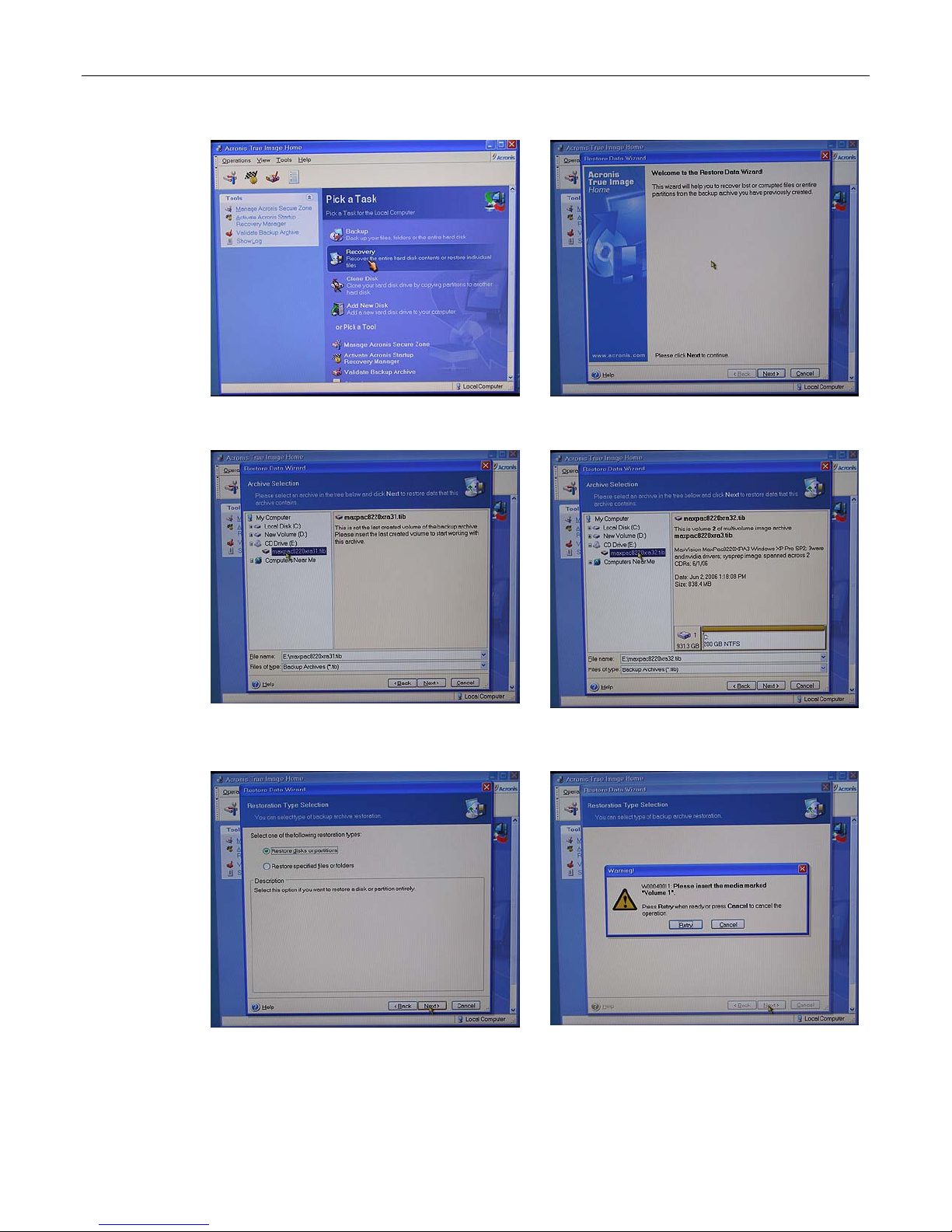
MaxPac Dual/Triple-Screen 8230 XRA2/3-Series User Operation and Maintenance Guide 81
Figure A-21
Figure A-22
Figure A-23
Figure A-24
Figure A-25
Figure A-26
Page 88
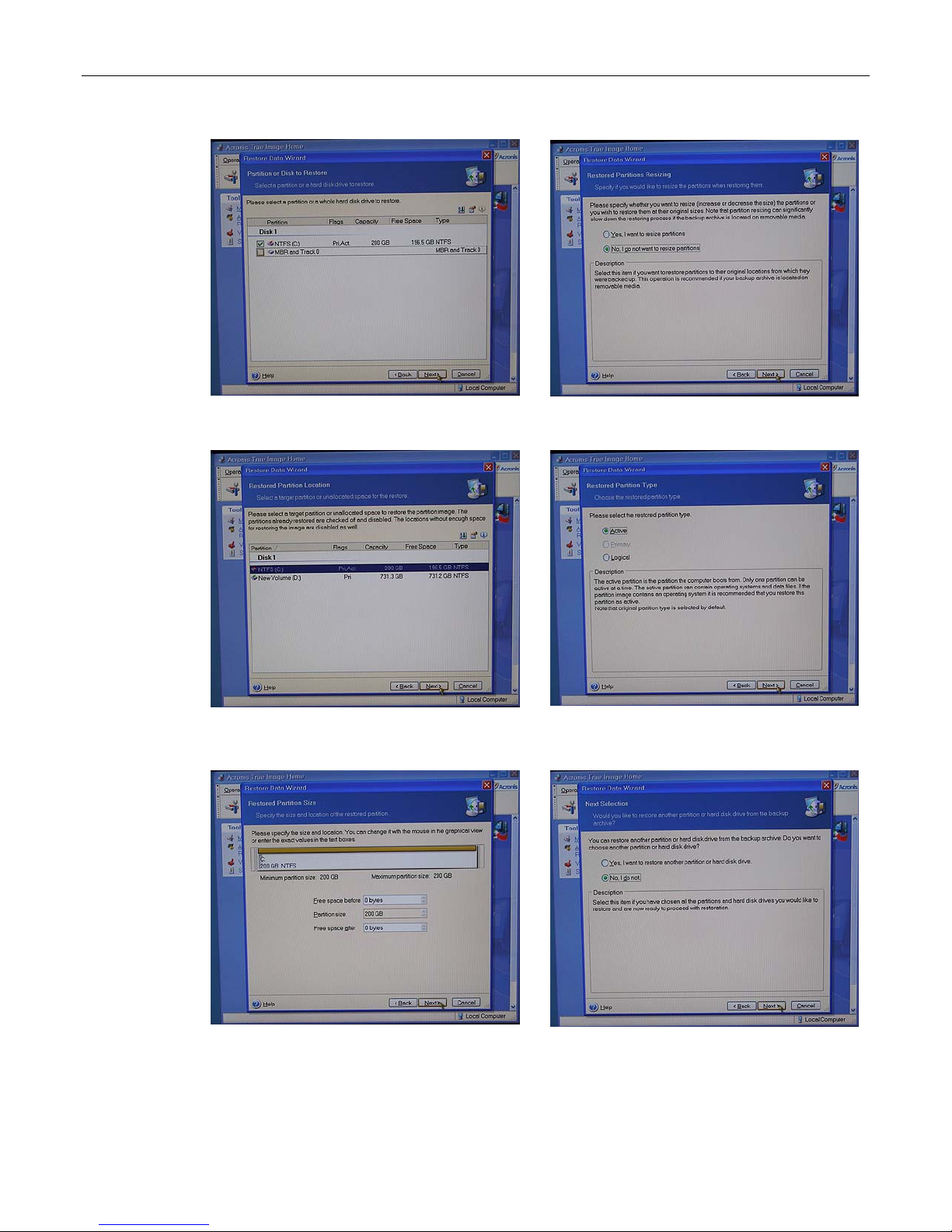
82 MaxPac Dual/Triple-Screen 8230 XRA2/3-Series User Operation and Maintenance Guide
Figure A-27
Figure A-28
Figure A-29
Figure A-30
Figure A-31
Figure A-32
Page 89
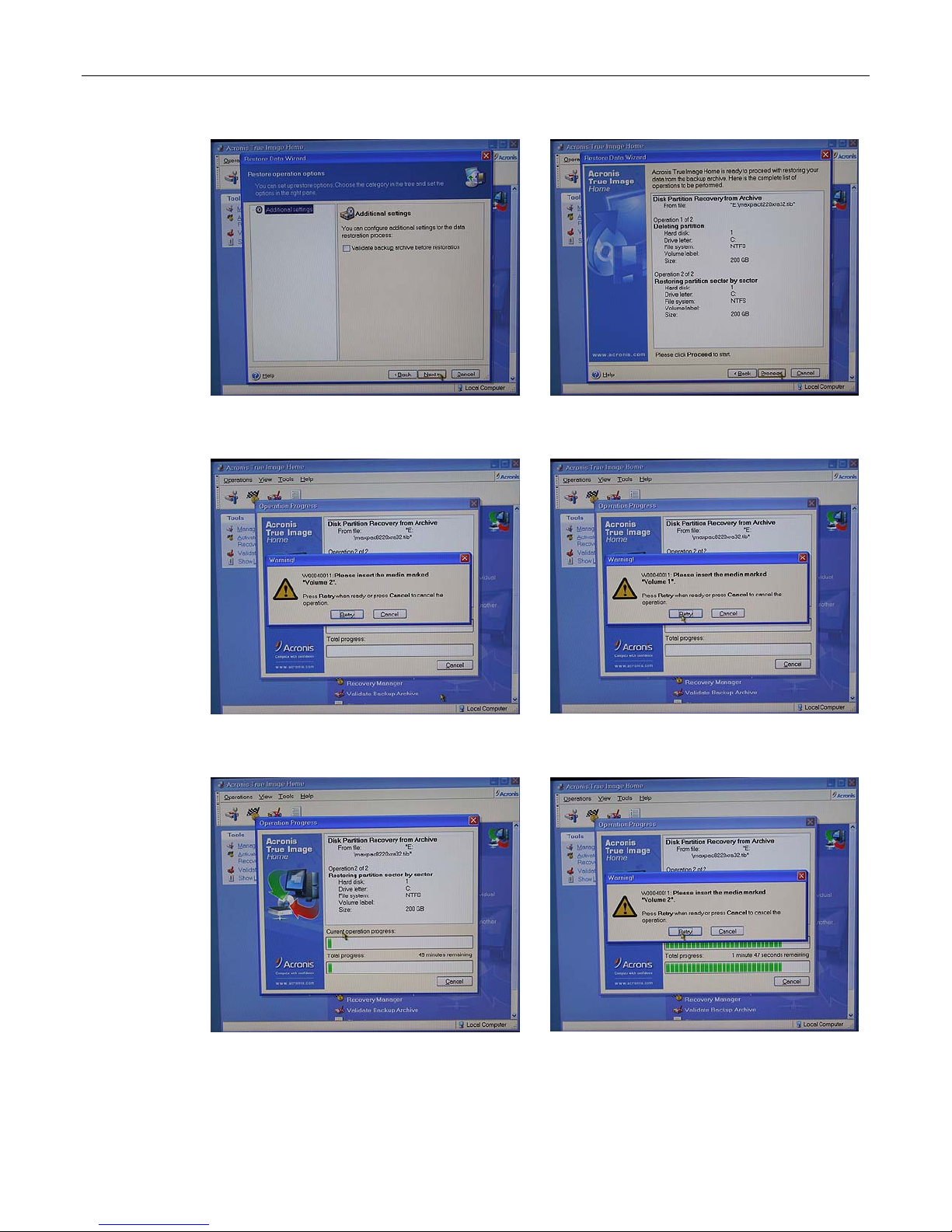
MaxPac Dual/Triple-Screen 8230 XRA2/3-Series User Operation and Maintenance Guide 83
Figure A-33
Figure A-34
Figure A-35
Figure A-36
Figure A-37
Figure A-38
Page 90
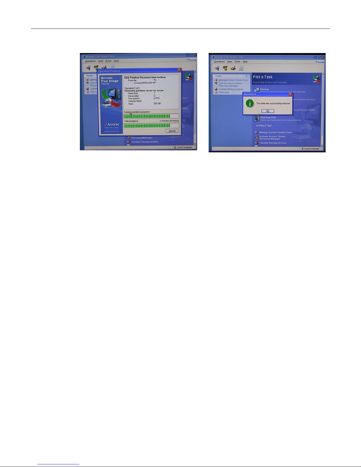
84 MaxPac Dual/Triple-Screen 8230 XRA2/3-Series User Operation and Maintenance Guide
Figure A-39
Figure A-40
Page 91

MaxPac Dual/Triple-Screen 8230 XRA2/3-Series User Operation and Maintenance Guide 85
Appendix B: Regular System
Maintenance
Cleaning Interior Dust
You should periodically check your system for the presence of interior dust and clean the enclosure
as required. (The frequency of such checks will be strongly dependent on your situation. Perhaps not
surprisingly, systems deployed in a desert environment, for example, will typically require such
cleaning more often than systems located in less rigorous settings.)
In order to clean the interior you should perform the following steps:
• Shut down the system and unplug the power cord.
• Open the display assembly into its service position as discussed in chapter 3.
• Using a commercially available compressed air PC cleaning product, blow the accumulated dust
out of the unit. Pay special attention to air passages, grills, and heat sinks.
• Close up the system.
Replacing the Lithium Battery
A Lithium Ion battery is included with the system motherboard. This battery is used for the Real Time
Clock circuit. The expected lifetime of the battery is approximately 5 years.
There is a danger of explosion if this battery is incorrectly replaced. Replace only with the same or
equivalent type recommended by the motherboard manufacturer. Dispose of used batteries according
to the manufacturer's instructions.
In order to replace the lithium battery you should perform the following steps:
• Shut down the system and unplug the power cord.
• Open the display assembly into its service position as discussed in chapter 3.
• Remove and replace the lithium battery according to the manufacturer's instructions.
• Close up the system.
Maintaining (Cleaning) the "Baghdad Filters"
1) Observe the two filters on the left-hand and right-hand sides of the main chassis (Figures B-1
and B-2, respectively). These filters are located over the air intake vents (any uncovered fans
act as exhausts).
Page 92
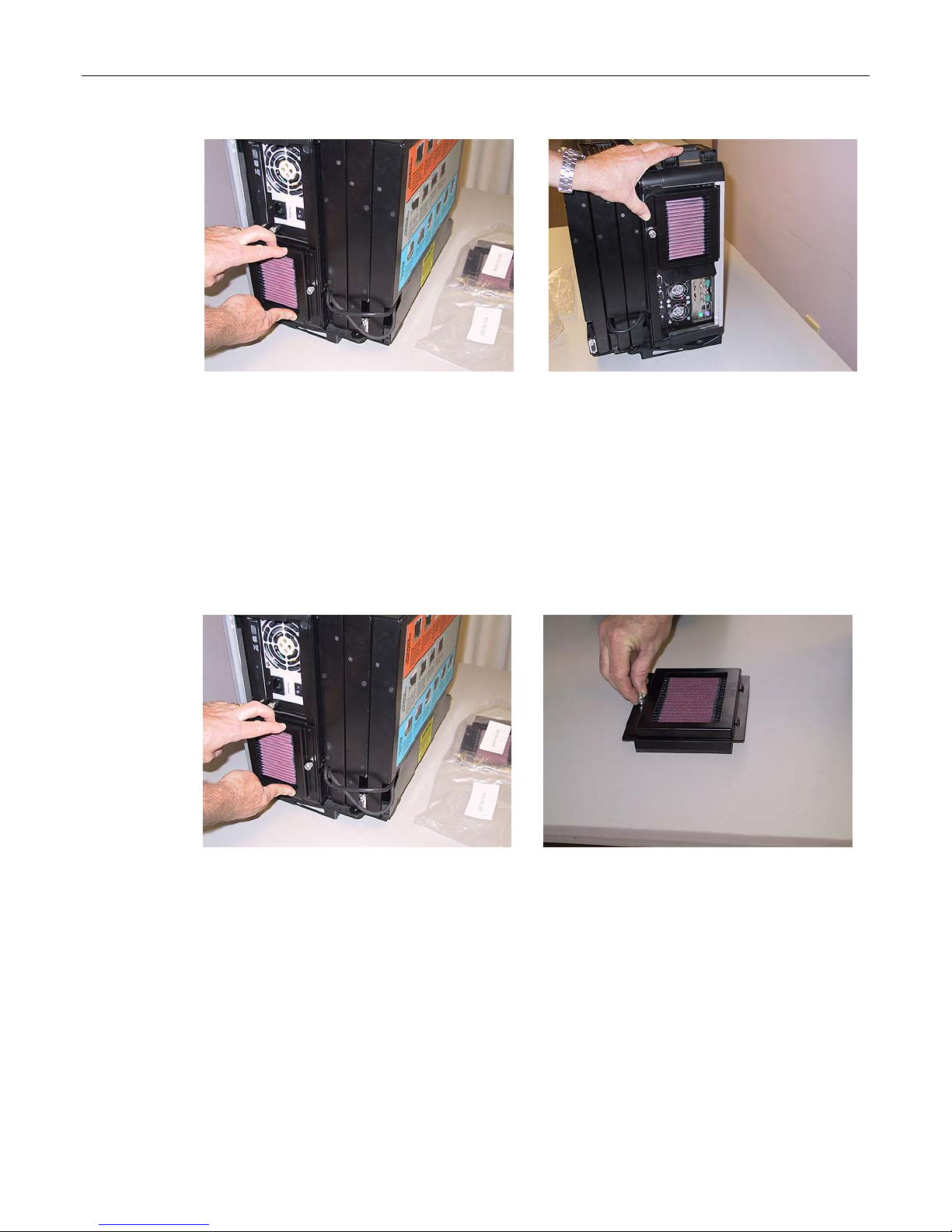
86 MaxPac Dual/Triple-Screen 8230 XRA2/3-Series User Operation and Maintenance Guide
Figure B-1
Figure B-2
Each of these filters is attached to the main chassis using a combination of a flange on the side of
the filter facing the back of the chassis and a Velcro strip on the side of the filter facing the front of
the chassis.
The filters should be cleaned as mandated by local conditions (a good rule of thumb is when the
filters look physically dirty). The following discussions are based on the left-hand filter. The same
actions apply to the right-hand filter. It is more efficient to clean both filters at the same time.
2) Starting with the filter on the left-hand side of the chassis, break the filter free of the Velcro on the
side of the filter facing the front of the chassis (Figure B-3).
Figure B-3
3) Unscrew the knurled knob holding the left-hand filter assembly as shown in Figure B-4 (this may
require the use of a Phillips #2 screwdriver).
4) Open the assembly as illustrated in Figure B-5.
Figure B-4
Page 93
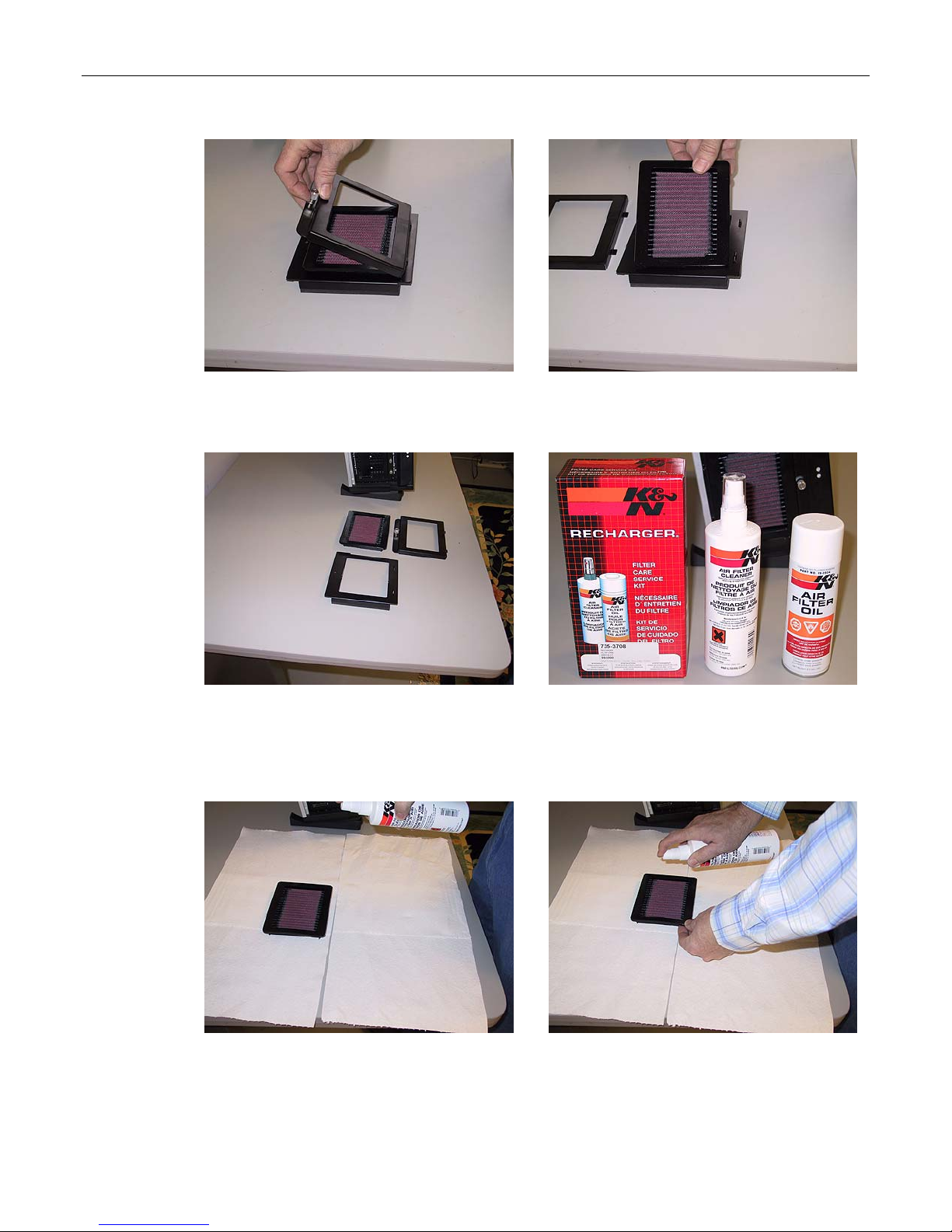
MaxPac Dual/Triple-Screen 8230 XRA2/3-Series User Operation and Maintenance Guide 87
Figure B-5
Figure B-6
5) Remove the filter element as illustrated in Figures B-6 and B-7.
Figure B-7
Figure B-8
6) The filter recharge kit (MaxVision Part Number 228-0002-0) comprises a pump spray cleaner and
an aerosol spray containing replacement oil (Figure B-8). Place the filter element on a working
surface that is protected by some form of absorbent, disposable material (Figure B-9).
Figure B-9
7) It is recommended that you first tap the filter element on the work surface to dislodge any large
embedded dirt particles, and then gently brush it with a soft bristle brush. Next, spray the cleaner
Figure B-10
Page 94
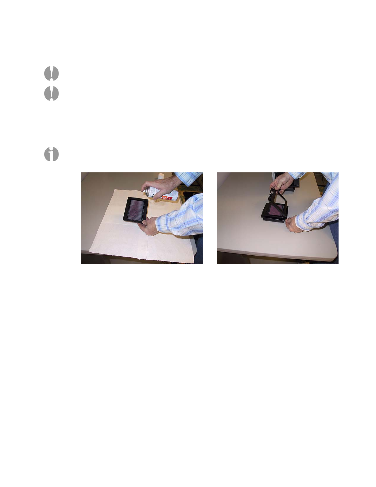
88 MaxPac Dual/Triple-Screen 8230 XRA2/3-Series User Operation and Maintenance Guide
onto both sides of the filter element (Figure B-10), leave for ten minutes, and then rinse the
element using a low-pressure water source (tap water is OK).
Note: Always apply the water from the "clean" side of the filter element.
Note: The use of other cleaning materials (including high-pressure air) may damage and/or
reduce the effectiveness of the filter element.
8) Shake off any excess water and then let the filter element dry naturally.
9) Spray replacement oil on the "dirty" side of the filter element (Figure B-11). Keep the nozzle about
three inches from the filter. Note that the cotton in the filter element will absorb and distribute the
oil into an even film; thus, it is important to use only a single pass for each area of the filter and to
not over-spray the filter.
Note: The filter oil is a compound of mineral and animal oil blended with special polymers to form
a very efficient barrier. Red dye is added to show just where you have applied the oil (this red
color will eventually fade, but the oil will remain and filter the air).
Figure B-11
Figure B-12
10) Let the filter stand for 20 minutes and then touch-up any spots that do not visibly show the red
dye contained in the oil.
11) Bring together the elements forming the filter assembly and secure using the knurled screw as
shown in Figures B-12 and B-13 (ensure that the oil side of the main filter element faces the side
of the assembly with the knurled screw).
Page 95
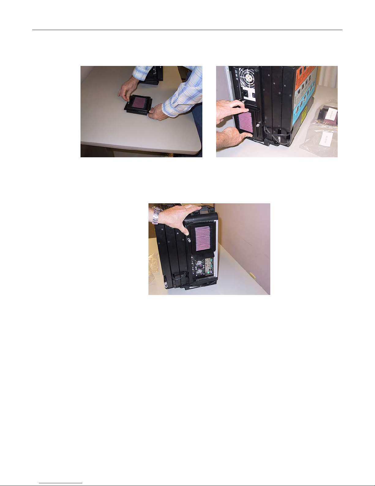
MaxPac Dual/Triple-Screen 8230 XRA2/3-Series User Operation and Maintenance Guide 89
12)
Figure B-13
13) Reattach the filter assemble to the main chassis by first slipping the flange of the assemble under
the silver strip at the rear of the chassis (Figure B-14) and then pressing the front edge of the filter
assemble so as to mate the Velcro.
Figure B-15
14) Repeat (or perform at the same time) the above steps for the right-hand filter (Figure B-15).
Figure B-14
Resetting the Motherboard BIOS
In the event that your motherboard BIOS is corrupted or lost completely (this could be caused by
failure of the lithium battery, electrostatic discharge, a major power surge, or user error), you may
reset the BIOS as follows:
1) Power the system down completely (a simple Start > Turn Off Computer > Restart command is
typically NOT recommended or sufficient) and then initiate the power-up sequence as discussed
in Chapter 1.
2) Due to extensive system initialization and verification checks, the BIOS boot-up process can take
a significant amount of time, especially in the case of systems with large amounts of memory. In
the case of a system containing 8 GB of RAM, for example, it can take 45 seconds before all
three LEDs above the numerical keypad on the keyboard flash. This is your cue to enter the BIOS
setup utility, which you achieve by pressing the <Delete> key on the keyboard. Note that the
system may not immediately respond to your pressing this key, which may be buffered until
Page 96
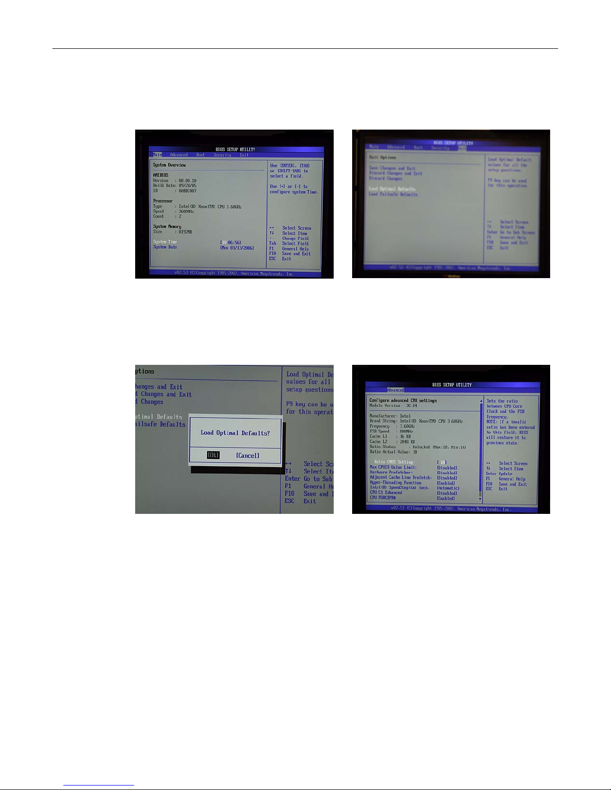
90 MaxPac Dual/Triple-Screen 8230 XRA2/3-Series User Operation and Maintenance Guide
higher priority initialization tasks have been completed. Once the system does respond to this
key, you will be presented with the System Overview screen of the BIOS Setup utility as shown
in Figure B-1.
Figure B-1
Figure B-2
3) Use the left/right arrow keys to select the Exit tab, and then use the up/down arrow keys to
highlight the Load Optimal Defaults item (Figure B-2).
4) Press the <Enter> key to select this item. You will be presented with a confirmation screen as
shown in Figure B-3.
Figure B-3
Figure B-4
5) Use the arrow keys to select the OK option, and then press the <Enter> key to select this item
and to load the optimal defaults for your system.
6) Press the <F10> key to save and exit the BIOS. This will cause a confirmation form to appear on
the screen. Use the arrow keys to highlight the OK option, and then press the <Enter> key to
save your changes to CMOS and exit the BIOS Setup utility.
Page 97
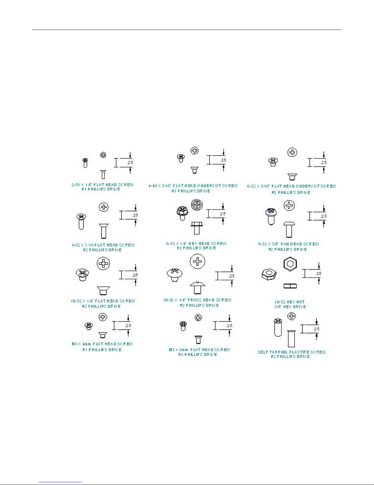
MaxPac Dual/Triple-Screen 8230 XRA2/3-Series User Operation and Maintenance Guide 91
Appendix C: Screws and
Required Tools
Screws
The various screws used in a MaxPac 8230-Series X-Class system are illustrated approximately full
size as shown in Figure C-1
Figure C-1. Screws used in MaxPac 8230-Series X-Class systems
Page 98
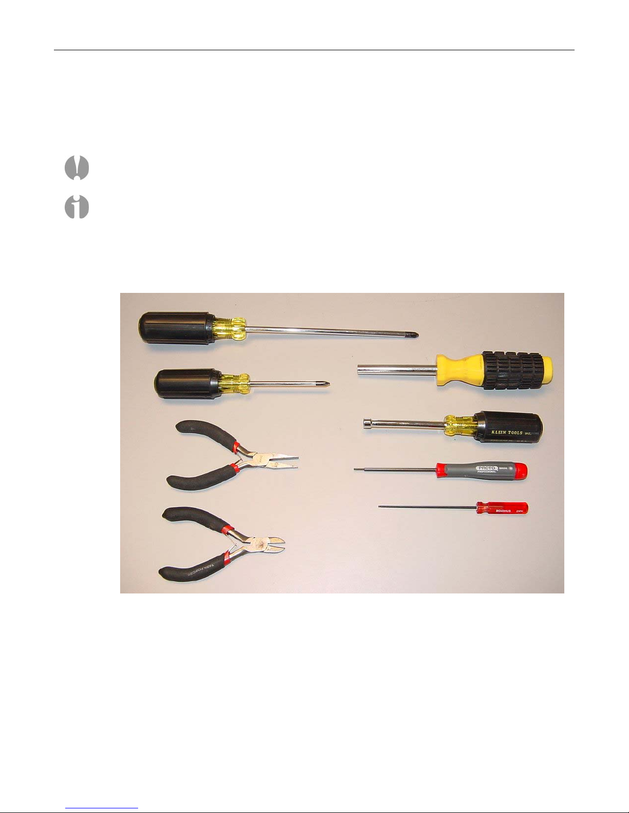
92 MaxPac Dual/Triple-Screen 8230 XRA2/3-Series User Operation and Maintenance Guide
Required Tools
Note: It is extremely important that you use only high-quality tools so as to avoid any slippage and
stripping of screw heads and threads.
Note: It is highly recommended that you use magnetized screwdrivers so as to prevent screws from
dropping inside the case and/or aiding in retrieving them if they do drop inside the case. (If your
screwdriver isn’t already magnetized, you can make it so by repeatedly “stroking” the blade with a
permanent magnet. Using a high quality universal screwdriver with replaceable Phillips #1 and #2 bits
is a good idea to ensure that your bits are always in excellent condition.
Most of the module replacement and upgrade procedures discussed in this chapter can be performed
using only a pair of #1 (small tip) and #2 (regular tip) Phillips screwdrivers.
For some procedures, however, needle-nose pliers will be of use, and you may have to cut cable ties
on occasion.
Also, in order to replace a display or the video distribution board you will need an appropriate Allen
key/tool.
Also, in order to remove the external video front plate assembly, you will need an appropriate Allen
key/tool.
Page 99

MaxPac Dual/Triple-Screen 8230 XRA2/3-Series User Operation and Maintenance Guide 93
Appendix D: Contacting MaxVision
Support (RMA and Serial Numbers)
Repairing/Replacing Products/Accessories
MaxVision will repair or replace products/accessories due to defects in material or workmanship, or
any failure of the hardware system to conform to written specifications. Warranty repairs will be
performed at MaxVision’s service center. Any replacement parts/products shall be new or
refurbished. Any repaired or replaced product will not extend the original warranty term of the product.
Additionally, this warranty period will not be extended as a result of the purchase of any additional
parts/products from MaxVision Corporation.
Contacting Technical Support and RMA Numbers
During the warranty period, MaxVision will provide technical support for hardware diagnosis via email
([email protected] or [email protected] ) or the technical support and
customer service hotline (800-533-5805). If MaxVision’s technical support determines that the product
is defective, MaxVision will issue a Return Material Authorization (RMA) number to the customer. The
customer is required to ship the product referencing the RMA number on the outside of the original
(or equivalent) packaging with a copy of MaxVision’s RMA form if provided. The return shipment must
be sent insured and prepaid to:
MaxVision Corporation
495 Production Avenue
Madison, AL 35758
USA
Attn: Support
MaxVision will ship the repaired or replaced product to the customer with freight prepaid if the
customer’s address is within United Stated of America (excluding Alaska, Hawaii, Puerto Rico and
U.S. possessions). Shipments to other locations will be shipped at the customer's expense.
MaxVision must receive notice of all events before the warranty period expires. NOTE: MaxVision will
not be responsible for data on the hard-disk drive. Before you ship the product(s) to MaxVision,
please back up your data from the hard-disk drive(s)or any other storage device(s) in the product(s).
 Loading...