

Page 1
User & Operating Instructions
MXL012/55Q/65Q/75Q
UK Contact:
Tel: +44 (0) 1553 811000
Email: support@maxview.co.uk
Web: www.maxview.co.uk
Maxview reserve the right to change
specifications without prior notice
MXL012SKYQINS Iss 1
Precision - SKY Q™ Only Variant
Page 2
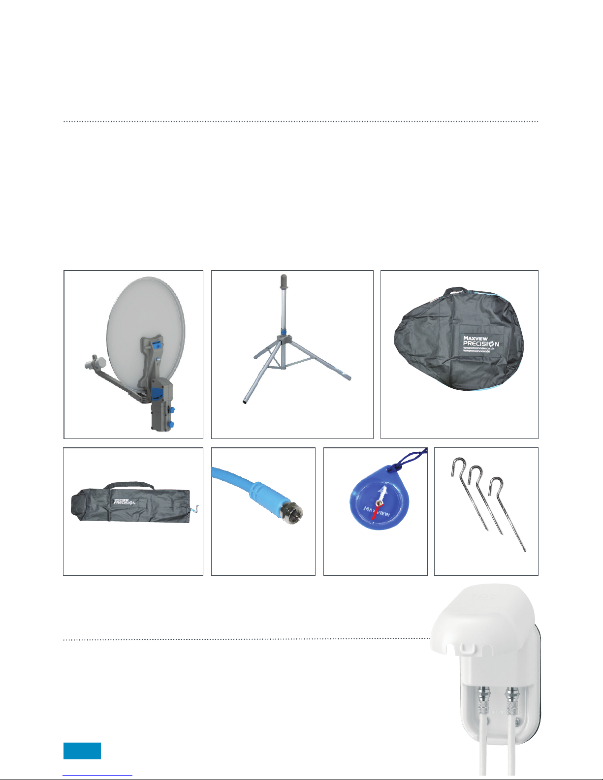
Kit Contents/Lieferumfang
Thank You!
For purchasing this product, we trust that you will get many years of enjoyment with this product.
Should you have any difficulty using your Precision Portable Satellite System please contact +44 (0)1553 81000.
Please retain these instructions for future reference.
Other equipment you will need to get started:
> SKY Q™ Receiver
Dish Unit Tripod Stand Dish Unit Holdall
Tripod Holdall
Twin 10m ‘F’ to ‘F’
Flexible Cable Ground PegsCompass
Contents
4-5 Get To Know Your Precision Kit
6-9 Dish Assembly & Set Up Guide
10 Line Of Sight
11 Connecting Your Precision
12 Using Your Integrated Sat Finder
14 Satellite Azimuth Adjustment Guide
14 Adjusting LNB Skew
Weatherproof Socket. Provides a waterproof and neat cable
entry into your vehicle.
Available separately from Maxview visit www.maxview.co.uk
or visit your local leisure stockist.
Optional Extras
2
B2007 - Twin
15 Skew Map
16 Elevation Zone Map
17 Quick Set Up Guide
18 Fault Finding
20 Dish Stowage
20 Care & Maintenance
20 Safety
20 2 Year Guarantee
Page 3
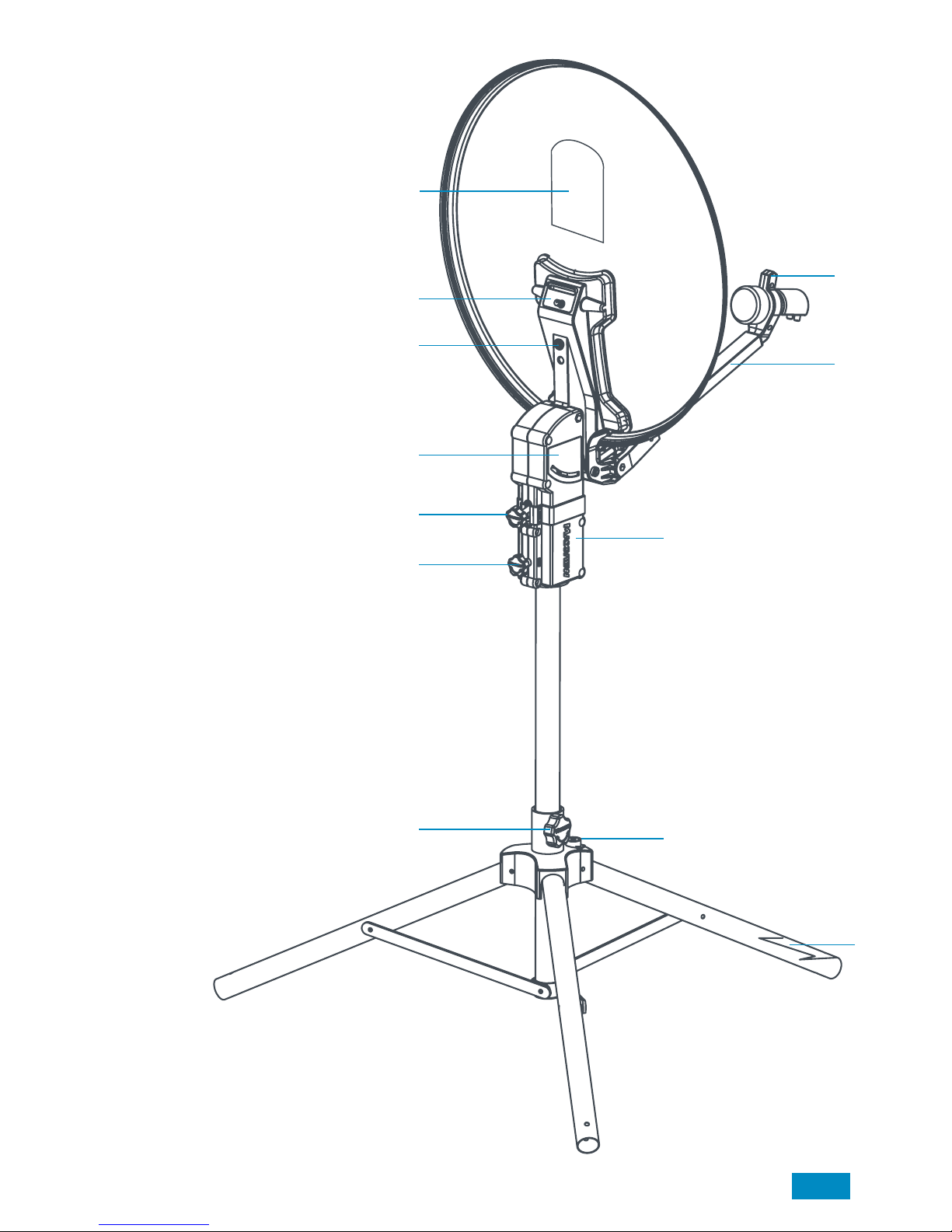
Get To Know Your Precision Kit
A. Elevation Map
Helps you set the correct elevation
angle to your current location.
B. Magnetic Arm Lock
To secure the LNB arm in a closed position.
C. Integrated Sat Finder
To help you align your satellite dish to the
satellite.
D. Folding LNB Arm
For compact storage of the system.
E. Coaxial Cable Ports
Easy access ports to attach your coaxial cable.
F. Elevation Indicator
Easy to view elevation angle read out.
G. Elevation Adjustment Knob
Turn to adjust elevation angle.
H. Tripod - Dish Unit Interface
Also contains Azimuth rotation stops.
This allows scanning in satellite zone only.
H. Azimuth Lock
To lock off system in correct
position once satellite has been located.
J. Tripod Lock
Used to secure the tripod in
assembled position.
K. Level indicator
A level tripod will allow for quicker set up
and a more accurate elevation reading.
L. South Leg
To point south using compass
during set up.
B
D
C
E
F
G
I
J
K
L
H
A
3
Page 4
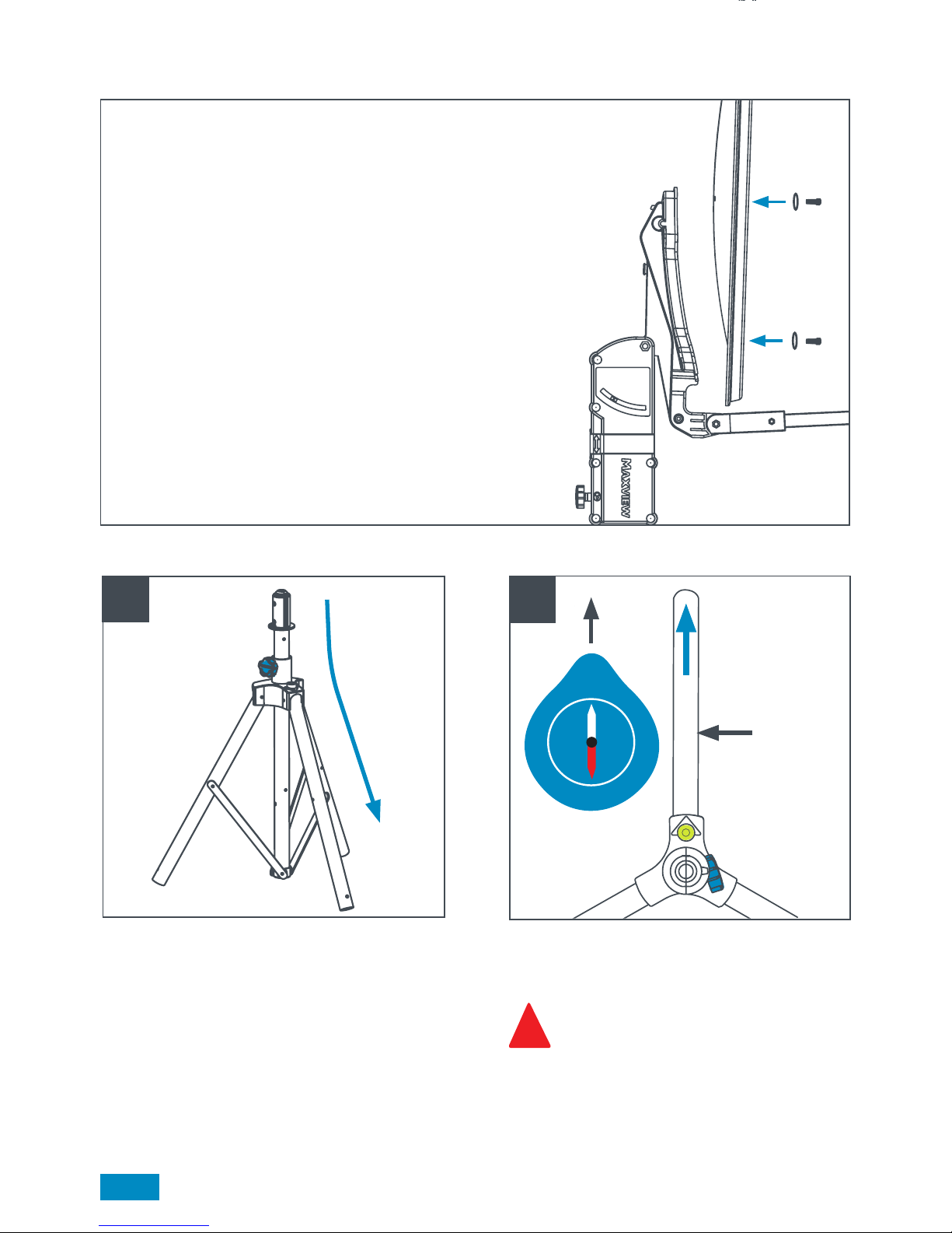
Use compass to align the tripod’s south leg
with South on the compass.
Ensure no line of sight obstructions in
South area. e.g. tall buildings or trees,
reference page 7.
Before you use your Precision you will need to attach the dish to the bracket.
You will find the screws/washers required for fitting the dish already inserted
in the bracket.
Remove these with a screwdriver taking note of the hole position you
removed these from. Offer up dish to bracket and re-insert screws/washers
to the matching holes. Firmly tighten screws against dish.
Dish Assembly
Set Up Guide
1
W
E
N
South Leg
2
Erect tripod by pushing firmly down to open
legs. Secure in open position by turning knob.
!
4
S
Page 5
South
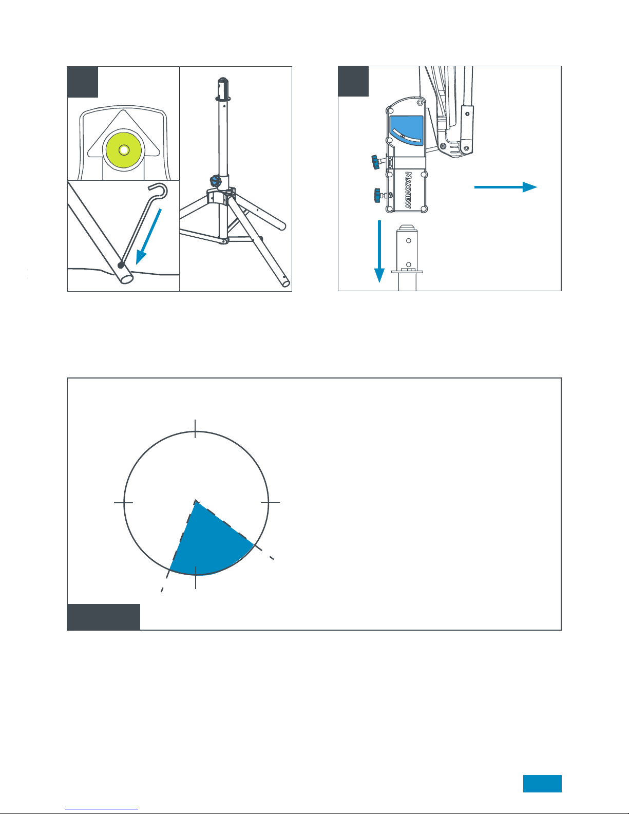
3
4
Level the tripod (use the level indicator as an
approximate guide only - not critical). Use the pegs
provided to secure tripod to the ground.
Mount dish unit onto tripod with the LNB arm
facing towards the south leg. (Reference Image 2).
Limited Satellite
Zone (Z). Astra 2
Note
Astra 2 (28.2º E) is used for SKY™
transmissions and is located within the
zone highlighted in blue.
Your precision tripod has been limited to
this zone to reduce scanning ensuring
satellite location is quick and easy.
(Z)
East
South
West
North
5
Approx only
Page 6

Pull down LNB arm from magnetic lock.
Use the elevation map to determine the required angle for your location. Set the dish to this angle using
the elevation knob and indicator. Use the Astra 2 angles for SKY™ transmissions.
Connect the Twin Flexible Cable to the cable
connection port. See page 8 for receiver end
connections.
The sat finder is wired
to the single port.
!
-°
+°
5
6
7
6
Page 7

Once satellite is located, lock off the rotation by
turning Azimuth lock knob. If you are experiencing
signal drop out, fine tune your signal by slightly
adjusting the elevation to improve TV picture
quality. Again, you can aid this process by using:
1. The integrated sat finder.
2. Your receivers built in sat finder.
Slowly rotate your dish from left to right
through the zone until the correct satellite
is located and a picture appears on your TV.
To aid the satellite location process you can
use the following methods:
1. Use the integrated sat finder (page 8).
2. Turn your TV and SKY Q™ receiver on and use
the screen as your guide that you have located
the satellite.
8 9
TV
ASTRA 2
7
IMPORTANT
Do not block the antenna’s line of sight to satellites in the southern sky at any time. Make sure
your dish has clean line of sight avoiding, buildings, trees and any other close by obstacles.
✔
✘
✘
✘
!
Line Of Sight
Page 8

Connecting Your Precision to your SKY Q™ Receiver
Main TV
HDMI cable
Please note the connectors to the SKY Q™ box can be connected either way around, function remains the
same.
SKY Q™ Satellite Receiver
8
Sky Q™ Box Set Up
- Enter SKY Q™ Menu Settings
- Highlight Settings and Enter 0, 0, 1, ‘select’ on the remote’
- Change LNB type from Dish to SCR
Using Your Integrated Sat Finder
Your Sat Finder is used to help you locate and find the best signal quality received from satellites.
Using the integrated sat finder.
Tune the sat finder by turning the knob fully anti-clockwise and then slowly clockwise until a deep tone is heard
and until 2-3 red LEDs are lit. Slowly rotate the dish from left to right until the pitch of the sat finder tone peaks
and more LEDs light up.
You should now have a picture on your TV.
Please note if you have a high tone on your sat finder and receiving no reception, you
may have located a different satellite as the sat finder is unable to distinguish between
different satellites. If this happens, repeat the above process, searching a slightly
different area and dish angle.
Fine tuning using the integrated sat finder.
Once a picture has been found, turn the sat finder down to a
deep tone and finely adjust your elevation and azimuth to
improve your signal and receive a higher tone with more lights lit.
!
Power SAT 1 SAT 2
HDMI
Page 9

Fault Finding
Remember, to recieve a clear satellite reception and picture, the dish must have the correct vertical (elevation)
and horizontal (azimuth) alignment.
1. I don’t want to use the Sat Finder, can I turn it off?
The Sat Finder measures frequency and can not determine between different satellites.
Simply turn the knob fully to the left. Your sat finder will now be silent and just a green light will be
illuminated. Keeping it in-line doesn’t affect your signal quality and uses very little power.
2. I can’t seem to get my tripod flat using the level indicator.
This is only a guide. As long as your tripod is on relatively flat ground you should locate the right satellite. If you
are on a more uneven surface, this is ok, however, your elevation may need to be different to the map in order
to offset the uneven surface.
3. My Sat Finder has a high pitched tone but I have no picture.
The Sat Finder measures frequency and can not determine between different satellites.
You may have located a different satellite to the one your receiver is set SKY Q™. Your receiver is set to Astra 2
and you may have located the wrong satellite. You will need to re-align your dish. See page 10 to gain an idea
of where you should point your dish and check elevation also.
4. The dish unit doesn’t seem to be dropping onto the tripod.
Ensure you rotation lock is not in the locked position. To do this you will need turn the knob
anti-clockwise.
5. I cant find the satellite in the zone I am limited to by the tripod.
Ensure the south leg is correctly positioned. This means it will be parallel to the South needle (white) on the
compass.
6. Will my satellite system work when pointing through trees and buildings?
Satellite, unlike TV signals, will not work through objects. The satellite dish must have a clear line of sight to the
satellite in the sky.
7. My dish unit does not rotate smoothly.
Ensure the Azimuth lock is fully released before rotating the system.
8. My system appears to have excessive movement between dish unit and tripod.
This is normal and required for rotation, however once you secure the azimuth lock, the system will become
stable and will not affect signal reception or quality.
9. I have noticed water inside my system, is this a problem?
The Precision kit has been designed for outdoor use. Therefore, it has been designed for water to pass through
the unit and exit easily. The system will dry out very quickly.
10. I am locked onto a satellite but I have no picture on my TV.
Check: 1 - You are on Astra 2 as point 3 above
2 - You have changed the LNB settings on your SKY Q™ Box as per page 11.
9
Page 10

ASTRA 2
Adjusting LNB Skew
Align Skew angle indication with arrow point or split line (highlighted in red). Twist LNB to desired angle
as shown. For correct angle see the next page for Skew Map.
Satellite Azimuth Alignment Guide
Use this general guide to help determine the
direction your desired satellite is located in the
Southerly zone.
Astra 2 is used for SKY Q™ transmissions.
Skew can be adjusted to maximise signal
in fringe areas.
20°
0°
20°
10°
10°
+
30°
30°
West
North
East
South
10
Page 11

Skew Map
-30° -28° -26° -24° -22° -20° -18° -16° -14° -12° -10° -8° -6° -4° -2°
6°
4°
2°
0°
11
Page 12

Elevation Zone Map
12
Page 13

Quick Set Up Guide
13
Page 14

Dish Stowage
For easy handling the holdall has been designed to simply slide over the dish
assembly whilst system is mounted onto the tripod. Ensure the elevation is set
to 30 to 50°
Note:
This bag has not been designed to be used for an outside cover for the system.
Care & Maintenance
The Precision has been designed to be maintenance and trouble free. For
optimum signal strength, keep the antenna clean from dirt, bugs and other debris.
1. Always handle the Precision kit with care. Do not drop the antenna.
2. Never power wash your Precision Kit. Keep the system clean from dirt,
bugs, and other debris by hand washing with mild soap and water.
DO NOT USE SOLVENTS TO CLEAN YOUR PRECISION SYSTEM.
Safety
> Take care when adjusting systems, to avoid finger/s being trapped.
> Always route cables carefully to avoid tripping over causing injury.
> Always switch power off at the mains before starting any electrical work.
2 Year Guarantee
!
The Maxview Precision is guaranteed against defective parts or workmanship for 2 years from the time of
purchase. This excludes any malfunction caused by improper use, accidental or malicious damage.
This does not affect your statutory rights. Please keep your receipt of proof of purchase.
14
Page 15

15
Page 16

Specifications
Application: Portable use in any outdoor environment
Compatibility: Compatible with SKY Q™ receivers only
Operation: Manual
Mount Type: Tripod
Skew Adjustment: Manual -30° to +30°
Coaxial Cale Length: 10m
Power: Passive. LNB powered through Coaxial cable from satellite receiver.
No separate power supply required.
Elevation Range: 10º to 50º (EU Variant)
Weight: 55cm variant: 6.1kg
65cm variant: 6.6kg
75cm variant: 7.0kg
16
 Loading...