

Page 1
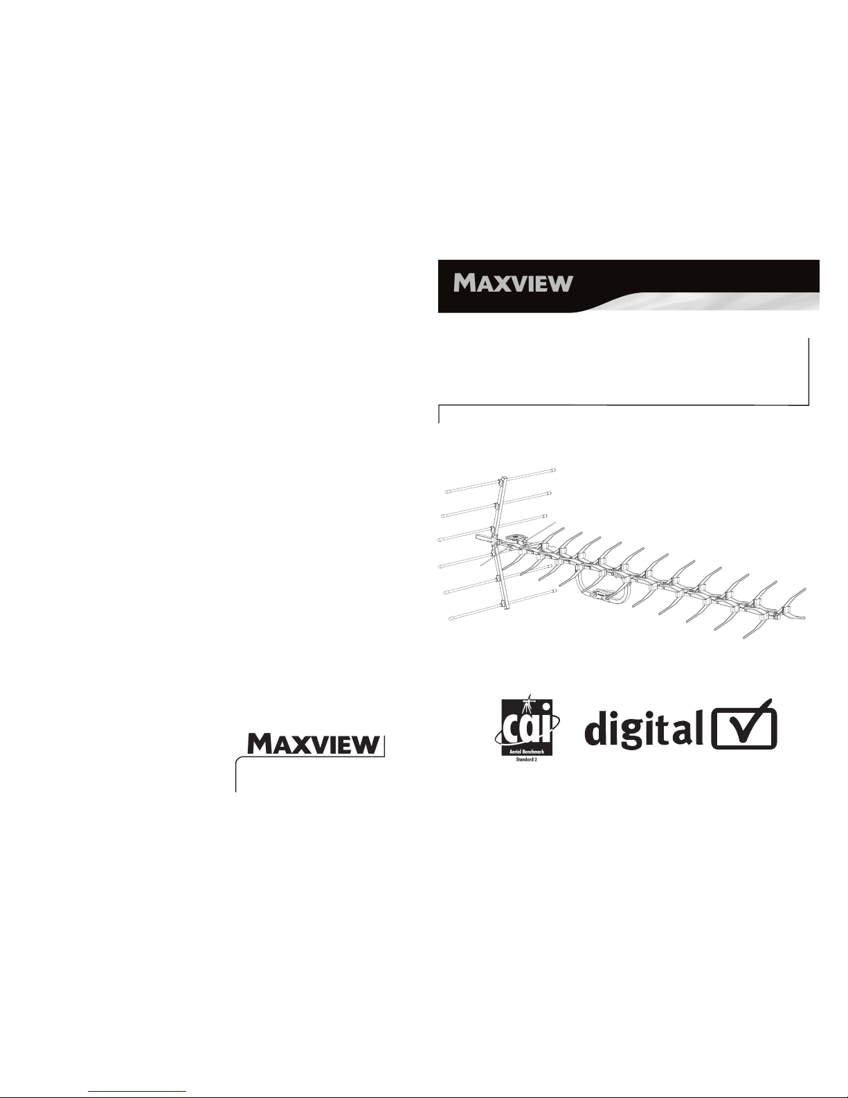
HIGH GAIN
DIGITAL TV AERIAL
ASSEMBLY INSTRUCTIONS & USER GUIDE
PLATI NUM* QUALIT Y RA NGE
PLE ASE N OTE - YOU W ILL R EQUIRE COAXI AL CA BLE
TO COMPLE TE TH E ASS EMBLY OF THIS AERI AL.
CAI /AB047
MX5 0W2
9111302 Iss 1
■ Helpline: +44 (0) 1553 811000
■ Email: [email protected]
■ Visit: www.maxview.co.uk
MXR 0025
Maxv iew r eserve the right to ch ange specif icati ons w ithout prio r noti ce
Approved product
Certification mark
Page 2
D
C
B
A
I
Q
R
S
T
U
MAS T CLA MP x 1
FOI L ‘V’ ELEM ENT x 22
DIP OLE x 1
REF LECTOR BRACK ET x 2
SUP POR
T A RM BR ACKET x 4
REF LECTOR ROD CLIP x 6
JOI NING PLATE x 2
ELE MENT x 1
END BUNG x 4
REF LECTOR BUNG x 12
SADD LE CL IP x 1
REF LECTOR BOOM x 2
SCR EW x 19
NUT x 7
WASHE R x 7
M5 x 25m m SCR EW x 7
SUP PORT ARM x 1
ELE MENT CLIP x 11
REA R BOOM x 1
FRO NT BO OM x 1
REF LECTOR ROD x 6
H:
I:
J:
K:
L:
M:
N:
A:
B:
C:
D:
E:
F:
G:
O:
P:
Q:
R:
S:
T:
U:
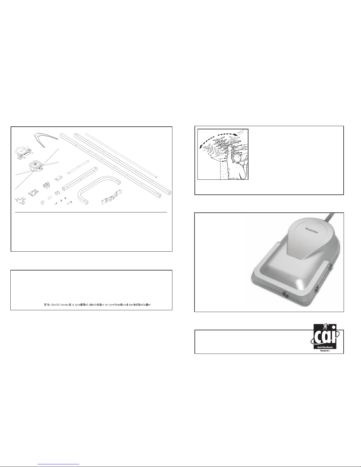
KIT CONTENTS CHECK LIST
Turn on your TV set. Refer to manufacturers instructions
to tune your TV into the available digital or analogue
channels. Select a tuned in analogue channel.
Next, carry out the following pr ocedures:
1. Turn your aerial to the LEFT until you lose the picture
(if alone turn the volume up and turn until you hear a
reduction in sound quality).
2. Remember this position and turn your aerial to the
RIGHT until you lose the picture/sound again.
3. Now point the aerial in the centre of these two points
and you will receive optimum reception.
To tune in Digital Terrestrial Television channels refer to
manufacturers instructions of your DTT equipment.
ALIGNING YOUR AERIAL
SAFETY FIRST - PLEASE READ
■ Ladder safe ty - alway s rea d and follo w the manu factur er’s instru ction labe l aff ixed t o the ladd er.
■ When workin g on insta llatio ns ou tside, bewa re of overh ead p ower lines.
■ Obser ve saf e wor king practi ces, tread caref ully and e nsure adeq uate l ighti ng is avail able in lo ft
or roof space .
■ To avoid injur y alw ays r oute c ables or w iring caref ully.
■ Always foll ow ma nufact urer’ s ope rating and safety inst ructio ns be fore using tools and/ or eq uipmen t.
■ Befor e sta rting insta llatio n che ck str uctur e is sound and check for h idden elect rical wirin g or plumb ing.
I
f i n dou bt co nsult a qua lifie d elec trici an or prof ession al ae rial instal ler
Thi s ae rial has successf ully pas sed a nu mber of
per formance tests to be c erti fied with this award.
MX5 0W2 Stand ard 2. Ver ified cer tific ation No. CA I/AB0 47
C
AI BENCHMARKED
NEED A BOOST?
Visit our website
www.maxview.co.uk
for our full range of
digital signal boosters.
If you are struggling to r eceive some of the digital
terrestrial channels clearly or are experiencing
picture break up on your TV, this may be due
to being in a very poor signal area and a
signal booster may be required.
When connected between your aerial
and TV/Set top box, a booster will
amplify the signal being received
from your closest TV
transmitter. The now
amplified signal should
then give you more
chance of receiving a
clearer, stronger and
more stable picture.
E
F
G
H
J
K
L
M
N
O
P
Page 3
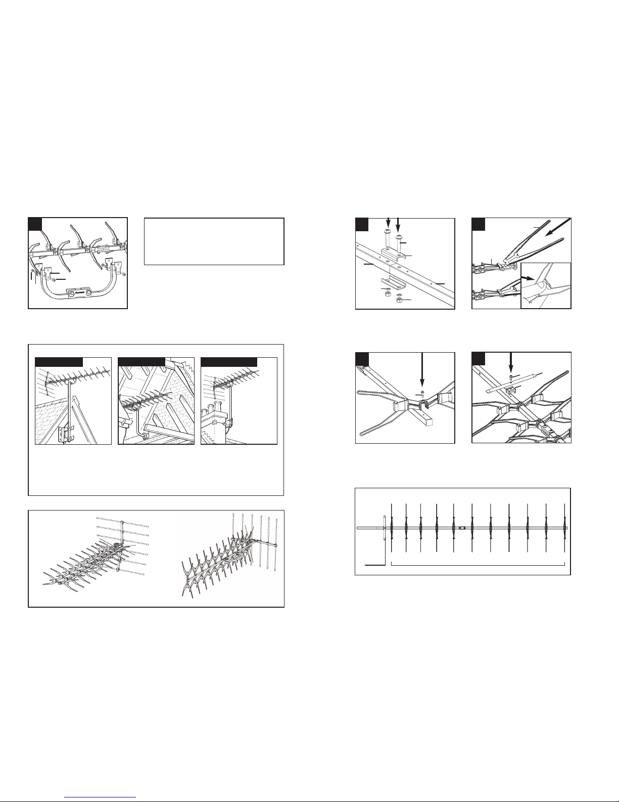
Join the 2 pieces of Boom together
using the Joining Plate and Screws.
Snap all Foil ‘V’ Elements into 11
Element Clips using your thumb.
Screw the 11 sets of Foil ‘V’ Elements
to the Boom.
Screw the Element to the Boom.
AERIAL ASSEMBLY INSTRUCTIONS
MAST CLAMP ASSEMBLY
Attach aerial to a suitable aerial mast**
(not supplied) using the supplied centre
mount bracket.
* Coaxial Cable Kit
Available from Maxview. Contact our Customer
Service (01553 811000) for your near est retail
outlet or order online at www.maxview.co.uk
Element reference guide.
P
G
T
S
O
N
R
B
M
M
H
K
11 x Foil ‘V’ Elements
**Loft or Chimney TV Aerial Fixing Kit
Element
1
1
2
3
4
TYPICAL AERIAL MOUNTING APPLICATION EXAMPL ES
WALL, LOFT & CH IMNEY FIXIN G KIT S ARE AVAILAB LE FR OM MA XVIEW
You should mount your aerial as high as possible on either a chimney, on an external wall,
or in the loft. Remember that in general, TV pictures improve with height and the less
obstructions between the aerial and the transmitter the better.
Now point your aerial in the direction of the transmitter by looking at neighbours aerials and
copying the direction they are pointing. If you decide to fit the aerial in your lof t, special care
should be taken when walking in the roof space.
Vertical mounting
recommended for
Relay TV transmitters
Horizontal mounting
recommended for
Main TV transmitters
POLARI SATION
Tip :
Loo k at outdoo r aer ials in yo ur ar ea to see which direc tion to po int y our a erial for b est r ecepti on.
Wall mou nted
Lof t mou nted
Chi mney mounted
E
P
N
O
Page 4
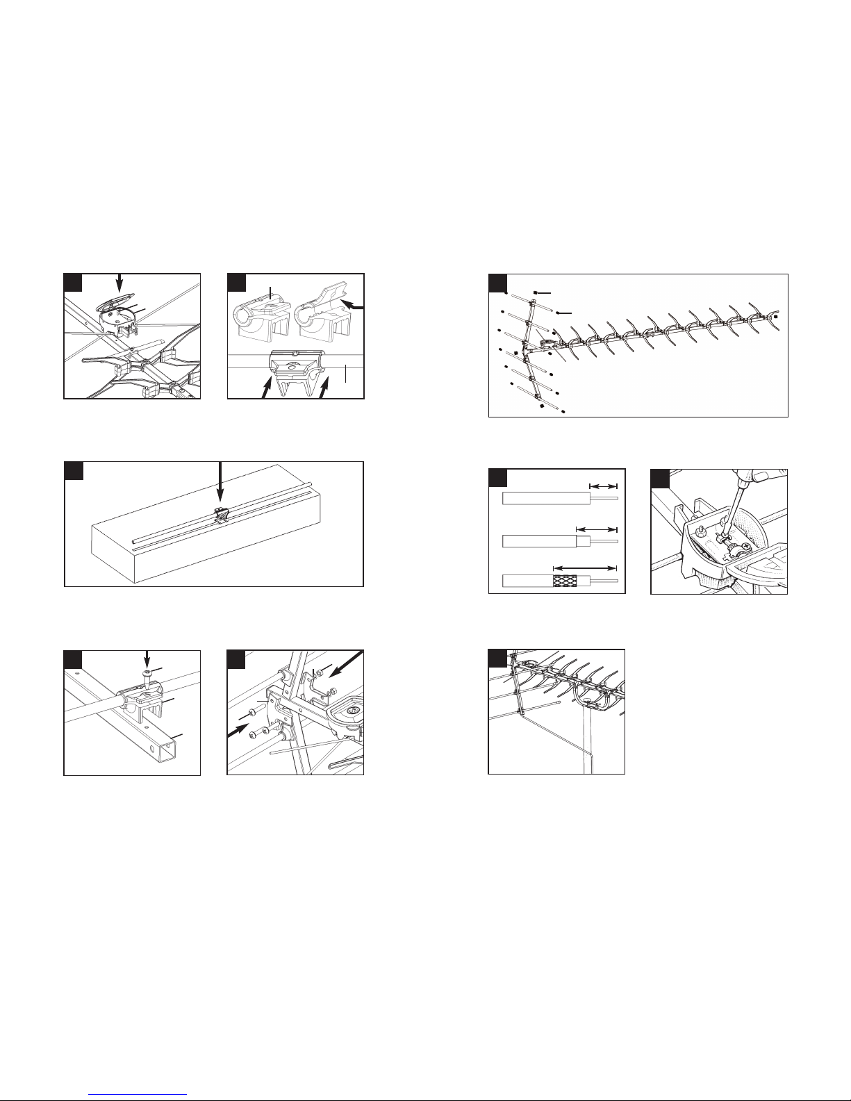
Place the Bungs on the Rods and Boom.
Use the template on the back of the box as a guide to centre the Clips onto the Rod.
Simply slide Clip along Rod to adjust.
Screw the Reflector Rods onto
the Reflector Boom.
Secure the Reflectors to the Aerial
Boom using the Reflector Brackets.
Screw the Dipole to the Boom.
Prise open clip using a scr ewdriver or
by hand. Firmly insert Rod into Clip
cavity and close.
C
M
L
F
Ensure cable routed as shown for
maximum performance.
U
F
P
N
D
O
J
I
5 6
7
8
9
10
3
M
Using a sharp knife prepare the
Coaxial Cable** as shown.
Loosen the screws on the two terminals.
Thread Coaxial Cable through Dipole.
Ensure outer braid does not touch
inner core. Tighten screws and Dipole
lid.
1
2
1
2
3
12mm
18mm
28mm
CONNECT ING COAXIAL CABLE (NOT SUPP LIED)
 Loading...