

Page 1
Assembly instructions
Turn on your T V set. Refer to ma nufact urers inst ructio ns to tune you r TV into the a vailable d igital/HD/3D
channels. Select a tuned-in channel. Next, carry out the following procedures:
1. Turn your aeri al to the LEF T until you los e the pictu re (if alone tu rn the volume up and tu rn until you hear a
reduction in sound quality).
2. Remembe r this positi on and turn your aeri al to the RIGH T until you lo se the pic ture/sound aga in.
3. Now point th e aerial in the centre of the se two points and you w ill receive op timum recept ion.
Digital & H D reception:
Reception of d igital terrestria l TV (DTT) sig nals is subject to:
1. Use with a DTT se t top box or inte grated TV w ith digital tuner/receiver
2. Satisfa ctory si gnal qual ity from DT T transmi tter
To receive terres trial HD ch annels you w ill require t he following:
1. An HD ready T V 2. Freeview HD re ceiver or TV with integ rated Freevi ew HD tuner/receiver
3. HD signals m ust be transmitte d in your loc al area. Visi t www.freev iew.co.uk for mor e informati on.
Safety warnings:
> Before sta rting in stallati on check st ructure i s sound and check for h idden ele ctrical w iring or plumbin g.
> When work ing on installatio ns outsid e, beware of overhead power l ines.
> Observ e safe worki ng practices, tread c arefully a nd ensure ad equate lig hting is avai lable in lof t/roof space.
> Always follow manufacturer’s operating and safety instructions before using tools and/or equipment.
> Ladder s afety - alway s read and follow the manu facture r’s instru ction lab el affixed to the ladde r.
> Ensure cab le is correc tly routed before fixin g into positi on, taki ng care not to over t ighten cab le clips.
> This prod uct may cont ain small pa rts - keep out of reach of ch ildren.
> After ins tallatio n make regula r maintenan ce checks.
> If in doubt co nsult a qua lified or prof essional a erial installer.
Contact:
Helplin e: +44 (0)1553 811000
Email: [email protected]
Web: w ww. max view. co.u k
Maxview re serve the right t o change specific ations withou t prior notice
9111316 I ss 2
MXR0010/KIT TV Aerial - 10 Element Kit
Model:
Aligning your aerial
Polarisation
Tip: Look at o utdoor aerials
in your area to s ee which
directi on to point you r
aerial for best reception.
Vertical mounting
recommended for
Relay TV transmitters.
Horizontal mounting
recommended for
Main TV transmitters.
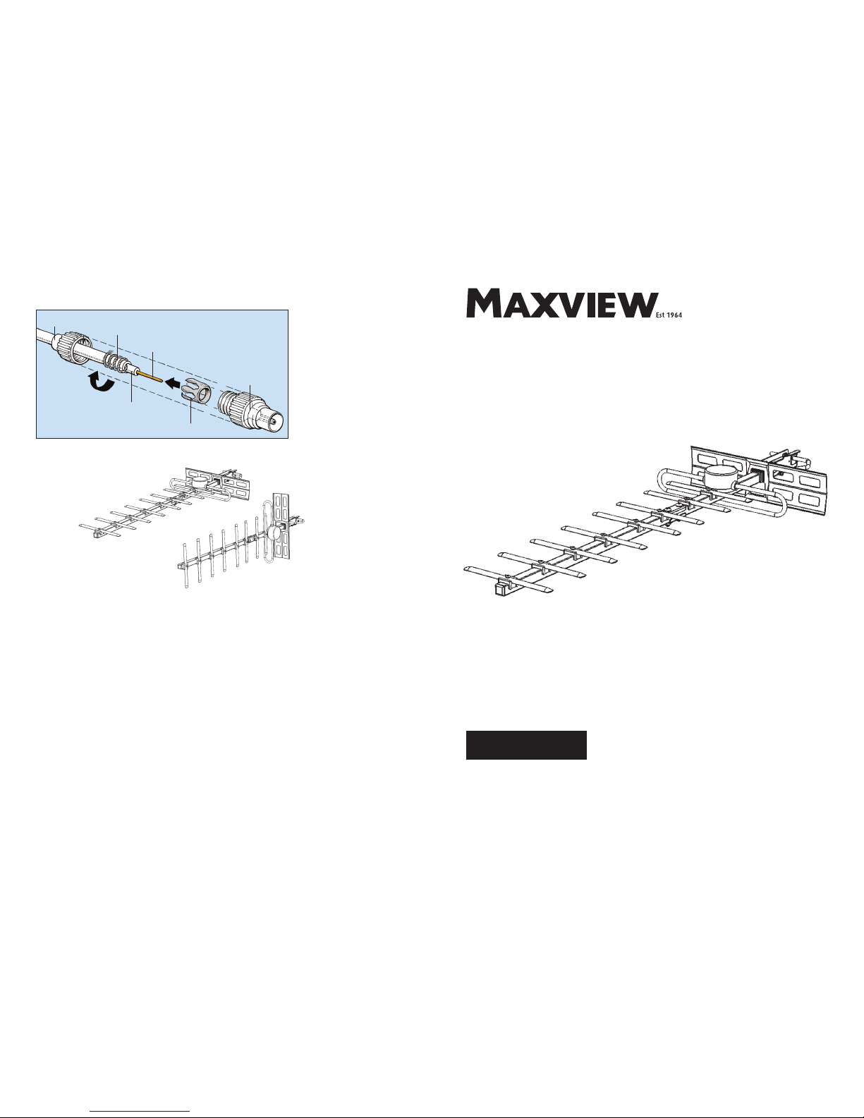
1) Cut cable to requ ired length.
2) Unscrew coaxial plug and
slide screw cap over cable.
3) Strip away appro ximately
23mm of outer i nsulatio n.
4) Gather strands of shielding
braid together and wind back
around th e outer insul ation.
Remove foil shield.
5) Strip away ab out half of th e
inner insulation around inner
core. Check t hat none of the
shielding braid is touching
the inner co re.
6) Open claw, slide ov er
screenin g braid and pinch to
tighten.
7) Re-assemble connector and
cut off in ner core wire flu sh
with plug.
Fitting Coaxial Plug
Inner
Braid
Outer insulator
Screw cap
Plug
Claw
Inner insulator
Note image f or reference on ly
bracket dif ferent to the one
include d in this kit
Page 2
1.
Pack contents check
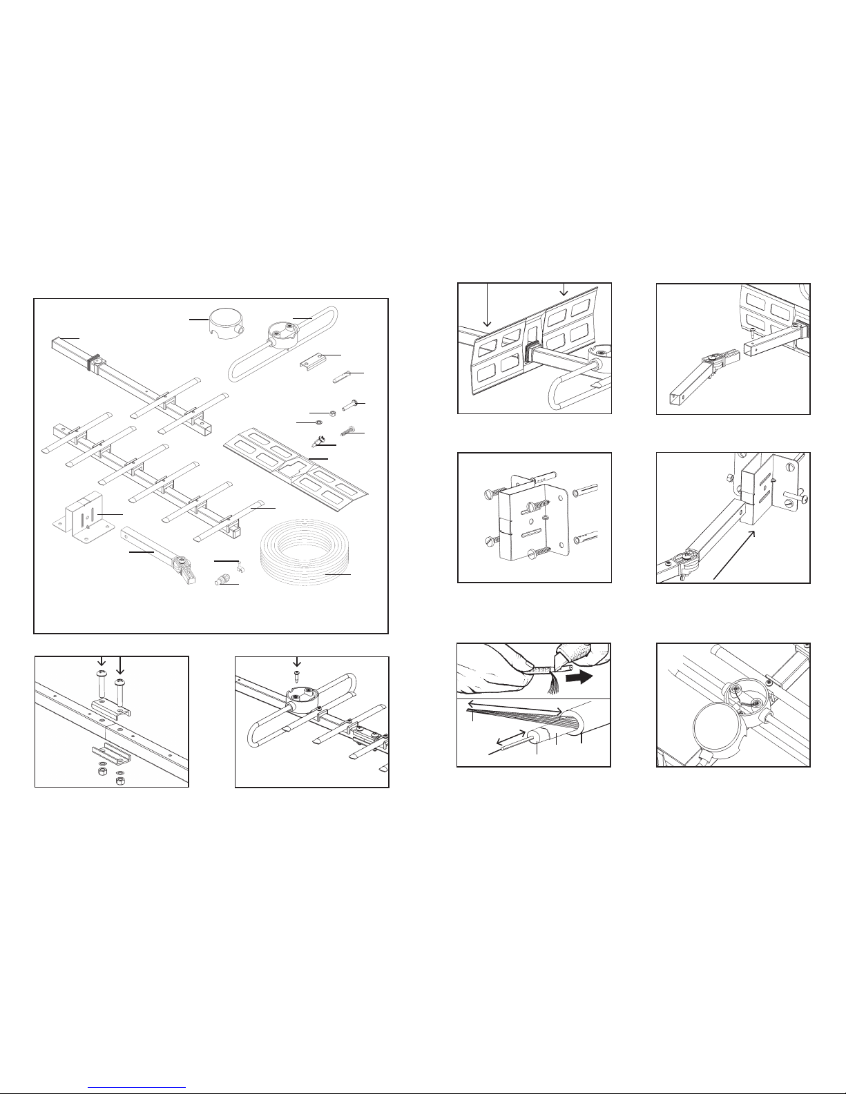
Join the 2 pi eces of boom to gether using the
joining p late, M5 x 20mm s crews M5 nut s and
5mm Shake Proo f Washers.
2.
3.
4.
Assembly
A. Rear Boo m x 1
B. Front Boo m x 1
C. Fixin g Bracket x 1
D. Swing Arm Bo om x 1
E. 10m Coaxia l Cable x 1
F. Dipole x 1
G. 6½ Screw x 2
L. No.10 1” Screw x 4
M. M5 Screw x 3
N. Washer x 2
H. Joinin g Plate x 2
I. Wall Plug x 4
J. Insulato r Cap x 1
K. M5 Nut x 3
Screw on firm ly the Dipole to the Bo om.
Slide on an d firmly pus h down the Refle ctor onto
the groove of the Reflector Bung.
Attach Swi ng Arm Boo m to the aeria l
Boom usin g a No.6½” Screw.
B
A
J
F
H
N
K
M
A
5.
6.
Mount Fix ing Bracke t to suitabl e wall using t he
No.10 1” Screws and Wall Plu gs.
Insert Swi ng Arm Boom into Fixi ng Bracket and
secure tog ether with a M 5 Screw and M5 Nut.
O. Coaxial Pl ug x 1
P. Cable Clip x 8
E
C
D
O
P
I
L
G
Connecting Coaxial Cable
1.
Thread coaxial cable through Dipole Cap. Strip
away 25mm of oute r insulato r. Gather outer b raid
strands a nd twist together. Remo ve 10mm of
inner insulation around inner core.
Loosen th e screws on the 2 te rminals in the
Dipole. F eed the inn er core to one of the
terminal s and the tw isted brai d into the othe r.
Tighten sc rews and clos e Dipole Cap.
Inner
core
25mm
10mm
Outer
braid
Outer
insulator
Inner
insulator
Foil
2.
 Loading...