

Page 1
Please read and save these instructions. Read carefully before attempting to assemble, install, operate or maintain the product described.
Protect yourself and others by observing all safety information. Failure to comply with instructions could result in personal injury and/or property damage! Retain instructions for future reference.
Air compressor units are intended to
provide compressed air to power pneumatic tools, operate spray guns and supply air for pneumatic valves and actuators. The pumps supplied with these
units have oil lubricated bearings. A
small amount of oil carryover is present
in the compressed air stream.
Applications requiring air free of oil
vapor should have the appropriate filter
installed. The air compressor units are to
be mounted per the instructions provided on a solid floor. Any other use of
these units will void the warranty and
the manufacturer will not be responsible for problems or damages resulting
from such misuse. Refer to the enclosed
“Replacement Parts Manual” to identify
compressor as single stage or two-stage.
Safety Guidelines
This manual contains information that is
very important to know and understand.
This information is provided for SAFETY
and to PREVENT EQUIPMENT PROBLEMS. To help recognize this information, observe the following symbols.
Danger indicates
an imminently hazardous situation which, if not avoided,
will result in death or serious injury.
Warning indicates
a potentially hazardous situation which, if not avoided,
could result in death or serious injury.
Caution indicates a
potentially hazardous situation which, if not avoided,
MAY result in minor or moderate
injury.
Notice indicates
important information, that if not followed, may cause
damage to equipment.
Operating Instructions Cast Iron Series
Breathable Air Warning
This compressor/pump is NOT
equipped and should NOT be used
“as is” to supply breathing quality
air. For any application of air for
human consumption, you must fit
the air compressor/pump with suitable in-line safety and alarm equipment. This additional equipment is
necessary to properly filter and purify the air to meet minimal specifications for Grade D breathing as
described in Compressed Gas
Association Commodity
Specification G 7.1 - 1966, OSHA 29
CFR 1910. 134, and/or Canadian
Standards Associations (CSA).
DISCLAIMER OF WARRANTIES
In the event the compressor is used
for the purpose of breathing air
application and proper in-line safety
and alarm equipment is not simultaneously used, existing warranties
are void, and Maxus disclaims any
liability whatsoever for any loss,
personal injury or damage.
Unpacking
After unpacking the unit, inspect carefully for any damage that may have
occurred during transit. Make sure to
tighten fittings, bolts, etc., before
putting unit into service.
Do not operate
unit if damaged
during shipping, handling or use.
Damage may result in bursting and
cause injury or property damage.
Since the air compressor and other
components (material pump, spray
guns, filters, lubricators, hoses, etc.)
used make up a high pressure pumping system, the following safety precautions must be observed at all times:
1. Read all manuals
included with this
product carefully.
Be thoroughly
familiar with the
controls and the proper use of
the equipment.
2. Follow all local electrical and safety
codes as well as the United States
National Electrical Codes (NEC) and
Occupational Safety and Health Act
(OSHA).
3. Only persons well acquainted with
these rules of safe operation should
be allowed to use the compressor.
4. Keep visitors away and NEVER
allow children in the work area.
5. Wear safety glasses and use
hearing protection when operating
the unit.
6. Do not stand on or use the unit as
a handhold.
IN556400AV 4/05
7. Before each use, inspect compressed
air system and electrical components
for signs of damage, deterioration,
weakness or leakage. Repair or
replace defective items before using.
8. Check all fasteners at frequent
intervals for proper tightness.
Motors, electrical equipment and controls can
cause electrical arcs that
Air
Compressors
Description
General Safety
© 2005
For parts, product & service information
visit www.maxustools.com
!
DANGER
!
WARNING
!
CAUTION
NOTICE
!
WARNING
MANUAL
!
DANGER
!
WARNING
Page 2

2
Air Compressors
will ignite a flammable gas or vapor.
Never operate or repair in or near a
flammable gas or vapor. Never store
flammable liquids or gases in the vicinity of the compressor.
Never operate compressor
without a beltguard. This
unit can start automatically without warning.
Personal injury or property damage could
occur from contact with moving parts.
9. Do not wear loose clothing or jewelry that will get caught in the moving parts of the unit.
Compressor parts may be
hot even if the unit is
stopped.
10. Keep fingers away from a running
compressor; fast moving and hot
parts will cause injury and/or burns.
11. If the equipment should start to
vibrate abnormally, STOP the
engine/motor and check immediately for the cause. Vibration is generally an indication of trouble.
12. To reduce fire hazard, keep
engine/motor exterior free of oil,
solvent, or excessive grease.
An ASME code safe-
ty relief valve with
a setting no higher than 200 psi for twostage compressors or 150 psi for single
stage compressors MUST be installed in
the air lines or in the tank for this compressor. The ASME safety valve must
have sufficient flow and pressure ratings
to protect the pressurized components
from bursting. The flow rating can be
found in the parts manual. The maximum
safe pressure rating for the pump is 200
psi (two-stage) or 150 psi (single stage).
The safety valve in the intercooler does
not provide system protection.
Maximum operat-
ing pressure is 175
psi for two-stage compressors and 135 psi
for single stage compressors. Do not operate with pressure switch or pilot valves
set higher than 175 psi (two-stage) or 135
psi (single stage).
13. Never attempt to adjust ASME safe-
ty valve. Keep safety valve free from
paint and other accumulations.
Never attempt to repair
or modify a tank!
Welding, drilling or any
other modification will
weaken the tank resulting in damage
from rupture or explosion. Always
replace worn, cracked or damaged tanks.
Drain liquid from
tank daily.
14.
Tanks rust from moisture build-up,
which weakens the tank. Make sure
to drain tank regularly and inspect
periodically for unsafe conditions
such as rust formation and corrosion
.
15. Fast moving air will stir up dust and
debris which may be harmful. Release
air slowly when draining moisture or
depressurizing the compressor system.
SPRAYING PRECAUTIONS
Do not spray flammable
materials in vicinity of
open flame or near ignition
sources including the compressor unit.
16. Do not smoke when spraying paint,
insecticides, or other flammable
substances.
17. Use a face mask/respirator when spraying
and spray in a well
ventilated area to prevent health and fire
hazards.
18. Do not direct paint or other sprayed
material at the compressor. Locate
compressor as far away from the spraying area as possible to minimize overspray accumulation on the compressor.
19. When spraying or cleaning with solvents or toxic chemicals, follow the
instructions provided by the chemical manufacturer.
Disconnect, tag and lock
out power source then
release all pressure
from the system before
attempting to install, service, relocate
or perform any maintenance.
Do not lift or move
unit without
appropriately rated equipment. Be sure
the unit is securely attached to lifting
device used. Do not lift unit by holding
onto tubes or coolers. Do not use unit
to lift other attached equipment.
Never use the
wood shipping
skids for mounting the compressor.
Install and operate unit at least 24”
from any obstructions in a clean, well
ventilated area. The surrounding air
temperature should not exceed 100
o
F.
This will ensure an unobstructed flow
of air to cool compressor and allow
adequate space for maintenance.
Do not locate the
compressor air inlet
near steam, paint spray, sandblast areas
or any other source of contamination.
NOTE: If compressor operates in a hot,
moist environment, supply compressor
pump with clean, dry outside air.
Supply air should be piped in from
external sources. For two-stage compressors only, use adapter kit
(TF060502AV) to connect piping to
compressor. Two adapter kits are needed for two-stage 10 and 15 HP units.
TANK MOUNTING
The tank should be bolted into a flat,
even, concrete floor or on a separate
concrete foundation. Vibration isolators
should be used between the tank leg
and the floor. Model MP345800AJ isolator pads are recommended for horizontal units. Model MP345700AJ isolator
pads are recommended for vertical units.
When using isolator pads, do not draw
bolts tight. Allow the pads to absorb
vibrations. When isolators are used, a
flexible hose or coupling should be
installed between the tank and service
piping.
Failure to properly
install the tank can lead
to cracks at the welded
joints and possible
bursting.
PIPING
Never use plastic
(PVC) pipe for compressed air. Serious injury or death
could result.
Any tube, pipe or hose connected to the
unit must be able to withstand the tem-
Installation
General Safety (Con’t)
!
WARNING
!
CAUTION
!
WARNING
!
CAUTION
!
DANGER
NOTICE
!
WARNING
!
WARNING
!
CAUTION
!
CAUTION
!
CAUTION
!
WARNING
!
WARNING
Page 3
3
Cast Iron Series
perature generated and retain the pressure. All pressurized components of the
air system must have a pressure rating
higher than or equal to the 200 psi for
two-stage compressors or 150 psi for single stage compressors ASME safety valve
setting. Incorrect selection and installation of any tube, pipe or hose could result
in bursting and injury. Connect piping system to tank using the same size fitting as
the discharge port.
INSTALLING A SHUT-OFF VALVE
A shut-off valve should be installed on
the discharge port of the tank to control
the air flow out of the tank. The valve
should be located between the tank and
the piping system.
Never install a
shut-off valve
between the compressor pump and the
tank. Personal injury and/or equipment
damage may occur. Never use reducers
in discharge piping.
When creating a permanently installed
system to distribute compressed air, find
the total length of the system and select
pipe size from the chart. Bury underground lines below the frost line and
avoid pockets where condensation can
gather and freeze.
Apply air pressure to the piping installation and make sure all joints are free
from leaks BEFORE underground lines
are covered. Before putting the compressor into service, find and repair all leaks
in the piping, fittings and connections.
WIRING
All wiring and
electrical connections must be performed by a qualified
electrician. Installations must be in
accordance with local and national
codes.
Overheating, short
circuiting and fire
damage will result from inadequate
wiring.
Wiring must be installed in accordance
with National Electrical Code and local
codes and standards that have been set
up covering electrical apparatus and
wiring. These should be consulted and
local ordinances observed. Be certain that
adequate wire sizes are used, and that:
1. Service is of adequate ampere rating.
2. The supply line has the same electrical characteristics (voltage, cycles and
phase) as the motor.
3. The line wire is the proper size and
that no other equipment is operated
from the same line. The chart gives
minimum recommended wire sizes for
compressor installations.
10 1/2” 1/2” 3/4” 3/4”
20 3/4 3/4 3/4 1
40 3/4 1 1 1
60 3/4 1 1 1
100 1 1 1 11/
4
MINIMUM PIPE SIZE
FOR COMPRESSED AIR LINE
Length Of Piping System
CFM 25’ 50’ 100’ 250’
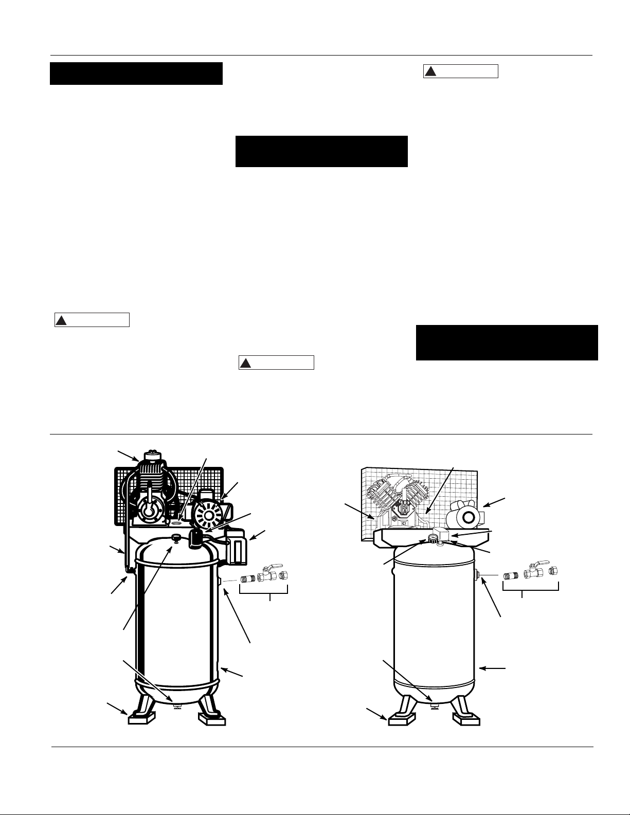
Figure 1 - Vertical Unit Identification
(available separately)
(available separately)
Installation (Con’t)
(available separately)
(available
separately)
(Not on
all units)
MINIMUM WIRE SIZE
USE 75°C COPPER WIRE
Single
Phase Three Phase
HP Amps 230V 208/230V 460/575V
SPL up to 22.0 10 AWG
5.0 8 AWG 12 AWG 14 AWG
7.5 8 AWG 10 AWG 12 AWG
10.0 N/A 8 AWG 12 AWG
15.0 N/A 6 AWG 10 AWG
25.0 N/A 3 AWG 8 AWG
!
WARNING
!
WARNING
!
CAUTION
Pump
Discharge
Tube
Check
Valve
Pressure
Gauge
Drain cock
Isolation Pad
Safety Valve Access
Motor
Pressure
Switch
Factory
Mounted
Magnetic
Starter
Tank
Shut-off
Valve
Discharge Port
Tank
Pump
Isolation Pad
Pressure
Gauge
Drain Cock
Discharge
Tube
Motor
Pressure
Switch
Safety Valve
Tank Shut-off Valve
Discharge Port
Tank
Page 4
4
Air Compressors
Recommended wire sizes may be larger
than the minimum set up by local ordinances. If so, the larger size wire should
be used to prevent excessive line voltage
drop. The additional wire cost is very
small compared with the cost of repairing or replacing a motor electrically
“starved” by the use of supply wires
which are too small.
GROUNDING
Improperly grounded
electrical components
are shock hazards.
Make sure all the components are properly grounded to prevent death or serious injury.
This product must be grounded.
Grounding reduces the risk of electrical
shock by providing an escape wire for
the electric current if short circuit
occurs. This product must be installed
and operated with a power cord or
cable that has a grounding wire.
MOTOR HOOKUP AND STARTER
INSTALLATION
Branch circuit protection must be provided as specified in the United States
National Electrical Code, Chapter 2,
“Wiring Design and Protection.” Article
210, using the applicable article “For
Motors and Motor Controllers,” (Article
430, Table 430-1 52).
IMPORTANT: Overload protection is
required for all motors. Certain motors
have this protection built-in. To determine if a motor has built-in overload
protection, refer to the frame size on
the motor nameplate.
Motors with frame size R56HZ, Y56Y or
L143T include built-in overload protection. No additional protection is
required. Use Figure 3 wiring diagram.
Motors with frame sizes 184T, 215T,
254T or 284T DO NOT have built-in overload protection. A magnetic starter is
required. Use Figure 4 wiring diagram.
To change to the alternate voltage
on three phase motors with 230/460
ratings:
1. Rewire motor per data plate on
motor or instruction sheet.
2. Check electric rating of magnetic
starter and replace thermal overload
elements or magnetic starter as
required. The voltage and amperage
ratings are listed on the motor
nameplate.
DIRECTION OF ROTATION
NOTE: Improper rotation will result in
reduced unit life.
The direction of rotation must be counterclockwise (as shown by the arrow on
the flywheel) while facing the flywheel
side of the pump. The motor nameplate
will show wiring information for counterclockwise rotation.
The proper direction is very important.
The direction of rotation of 3 phase
motors can be reversed by interchanging any two motor-line leads. For single
phase motors, refer to the motor
nameplate.
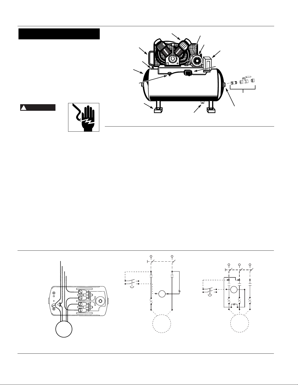
Figure 2 - Horizontal Unit Identification
Line
Ground
L2
L1
Figure 3 - For Motor Frame Sizes R56HZ,
Y56Y or L143T. Refer to Motor Nameplate
Motor
L1
L2
Pressure
Switch
Thermal
Units (3)
L3
T2
Circuit Breaker or
Fused Disconnect
X2
Motor
Over
Load
Coil
T3
T1
Three Phase
Wiring Diagram
L1
Pressure Switch
Thermal
Units (3)
L2
Circuit Breaker or
Fused Disconnect
Motor
Over
Load
Coil
T2
T1
X2
Figure 4 - For Motor Frame Sizes 184T, 215T, 254T or 284T. Refer to
Motor Nameplate
Single Phase/
Three Phase
Wiring Diagram
Single Phase
Wiring Diagram
L3 (for 3 phase wiring only)
Installation (Con’t)
(Not on
all units)
(available separately)
(available separately)
!
DANGER
Pump
Discharge
Tube
Check Valve
Tank
Pressure
Gauge
Isolation Pad
Drain cock
Safety Valve Access
Motor
Factory Mounted
Magnetic Starter
Pressure Switch
Tank Shut-off
Discharge Port
Valve
Page 5
5
Cast Iron Series
IMPORTANT: Check motor rotation
before operating the compressor.
All lubricated compressor pumps dis-
charge some condensed water and oil
with the compressed air. Install appropriate water/oil removal equipment
and controls as necessary for the
intended application.
Failure to install
appropriate
water/oil removal equipment may result
in damage to machinery or workpiece.
GUARDING
The belt guard provided
must be installed before
operating the unit.
All moving parts must be guarded. All
electrical covers must be installed
before turning on the power.
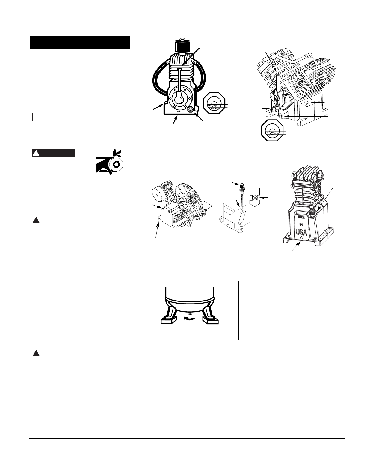
LUBRICATION
THIS UNIT CON-
TAINS NO OIL.
Before operating compressor, fill
crankcase with compressor oil according to the oil capacity chart listed in
“Replacement Parts Manual.”
Some residual oil may still be in the pump
leaving a thin coat on the sight glass,
however; there is not enough oil to operate the unit. Fill pump with single-viscosity, ISO100, non-detergent, compressor
oil. Use part number ST126700AV compressor oil or Mobil 1
®
5W30 or 10W30
synthetic oil may also be used. Add oil
only through the oil fill plug. Pouring oil
into any other orifice will cause oil to leak
and spray out during operation. Fill to
the center of the sight gauge or maximum mark on dipstick (see Figure 5).
Using any other
type of oil may
shorten pump life and damage valves.
RECOMMENDED BREAK-IN PERIOD
The compressor should be run continuously for one hour to allow proper
seating of the piston rings.
1. Open drain cock completely and run
the compressor for 60 minutes (See
Figure 6).
150 psi for two-stage compressors or 120
psi for single stage compressors by opening the drain cock or an air valve connected to the tank or hose. Run the
pump for an hour at a time at least once
a week or more often if the condensation reoccurs.
IMPORTANT: Change oil after first 50
hours of operation.
PRESSURE SWITCH, START - STOP
NOTE: This compressor has a maximum
operating pressure of 175 PSI for twostage compressors or 135 PSI for single
stage compressors. Do not alter pressure
settings on control components above
this limit.
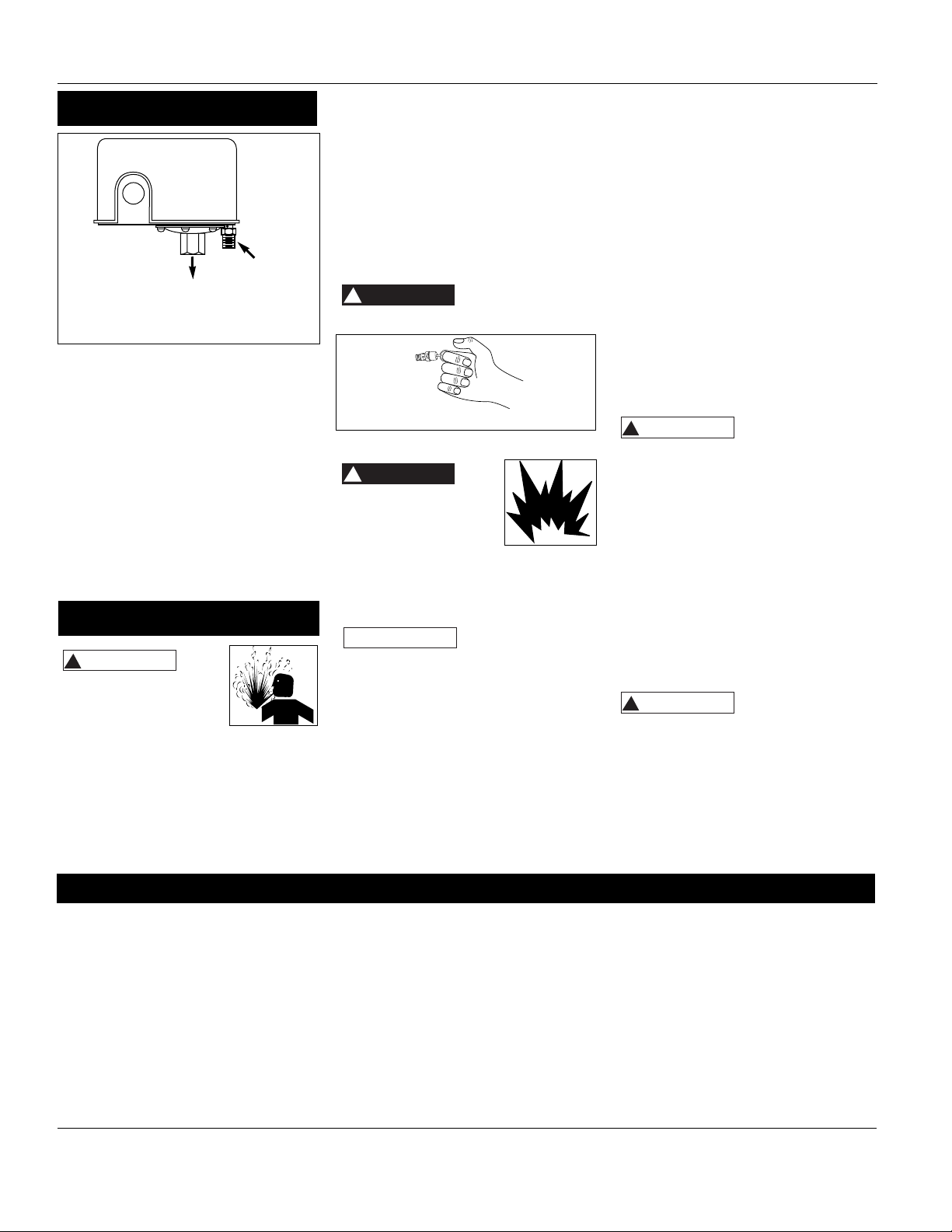
The compressor unit starts and stops
based on preset pressure switch settings. The pressure switch contains an
unloader which is a small valve that
vents air to allow the motor to start
easily (See Figure 7).
2. Turn off the compressor and close
drain cock. The compressor is now
ready for use.
If the compressor is run under humid
conditions for short periods of time, the
humidity will condense in the crankcase
and cause the oil to look creamy. Oil
contaminated by condensed water will
not provide adequate lubrication and
must be changed immediately. Using
contaminated oil will damage bearings,
pistons, cylinders and rings and is not
covered under warranty. To avoid water
condensation in the oil, periodically run
the compressor with tank pressure near
Operation
Figure 6 - Opening Drain Cock
Figure 5 - Oil Fill Diagrams
Dipstick
and Oil
Fill
Drain on Side
Drain
Dipstick
and Oil Fill
NOTICE
!
DANGER
!
CAUTION
!
CAUTION
Breather
Cap
Oil
Fill Plug
Oil Drain Plug
Sight Gauge
Dipstick
Breather
Add Oil
Full
Low
Breather
Cap
Oil
Sight
Gauge
Max
Low
Fill
Line
Full
Low
Fill Plug
Oil
Drain
Plug
Page 6
Air Compressors
CONTINUOUS RUN OPERATION
To convert to continuous run operation a
separate unloading device must be
installed by the user between the pump
and the tank. The existing check valve
must be removed.
CRANKCASE BREATHER
During severe operating conditions or
initial start-up, some oil may accumulate
at the crankcase breather opening. This
is normal and will diminish as the pump
accumulates run time and the piston
rings become fully seated.
Disconnect, tag and lock
out power source then
release all pressure from
the system before
attempting to install, service, relocate
or perform any maintenance.
In order to maintain efficient operation of the compressor system, check
the air filter and oil level before each
use. The ASME safety valve should also
be checked daily (See Figure 8). Pull
ring on safety valve and allow the ring
to snap back to normal position. This
valve automatically releases air if the
tank pressure exceeds the preset maximum. If air leaks after the ring has
been released, or the valve is stuck and
cannot be actuated by the ring, the
ASME safety valve must be replaced.
Do not attempt to
tamper with the
ASME safety valve.
TANK
Never attempt to repair
or modify a tank!
Welding, drilling or any
other modification will
weaken the tank resulting in damage
from rupture or explosion. Always
replace worn, cracked or damaged
tanks.
Drain liquid from
tank daily.
The tank should be carefully inspected
at a minimum of once a year. Look for
cracks forming near the welds. If a crack
is detected, remove pressure from tank
immediately and replace.
COMPRESSOR LUBRICATION
See Operation. Add oil as required. The
oil and oil filter should be changed every
three months or after every 500 hours of
operation; whichever comes first. Only
pressure lubricated pumps have an oil
filter.
AIR FILTER
Never run the compressor pump without
an intake air filter nor with a clogged
intake air filter. Use compressed air to
blow the filter clean. Do not wash or oil
the element. If it cannot be blown clean,
the filter must be replaced. Operating
compressor with a dirty filter can cause
high oil consumption and increase oil contamination in the discharge air.
INTERCOOLER (TWO-STAGE
COMPRESSORS ONLY)
Intercooler fins are
sharp, always wear
gloves and use care when you clean or
work near the intercooler.
Weekly, check the intercooler to be
sure all fittings are secure and tight.
Blow all dirt, dust and other accumulations from the intercooler fins.
COMPONENTS
Turn off all power and use light air
pressure to blow dust and foreign
material from cylinder head, motor, fan
blades, air lines, intercooler and tank on
a monthly basis.
BELTS
Lock out and tag
the power then
release all pressure from the tank to prevent unexpected movement of the unit.
Check belt tension every 3 months.
Adjust belt tension to allow 3/8 to 1/2”
deflection with normal thumb pressure.
Also, align belts using a straight edge
against the face of the flywheel and
6
Operation Daily Weekly Monthly 3 Months
Check Safety Valve
Drain Tank (See Figure 6)
Check Oil Level
Clean or Change Air Filter
Check Intercooler (two-stage
compressors only)
Clean Unit Components
Check Belt Tightness
Change Oil (See Figure 5)
Change Oil Filter
(Pressure lubricated pumps only)
MAINTENANCE SCHEDULE
Operation (Con’t)
Maintenance
Figure 8
Figure 7 - Pressure Switch
Unloader
To tank pressure
!
WARNING
!
DANGER
!
DANGER
NOTICE
!
WARNING
!
WARNING
Page 7
7
Cast Iron Series
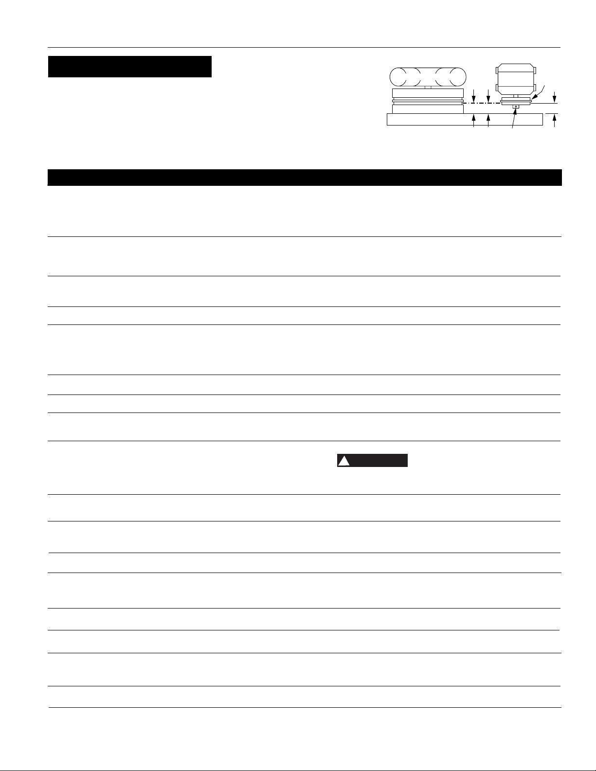
Figure 9 - Top View
touching the rim on both sides of the
face. The belts should be parallel to this
straight edge (see Figure 9). Dimension
A should be the same as B and C to
ensure proper alignment of the belts.
Maintenance (Con’t)
Slots in the bed-plate allow for sliding
the motor back and forth to adjust belt
tension.
STORAGE
If compressor is to be stored for a short
period of time, make sure that it is
stored in a normal position and in a
cool protected area.
Troubleshooting Chart
Symptom Possible Cause(s) Corrective Action
1. Low voltage or no voltage
2. Shorted or open motor winding
3. Malfunctioning check valve or unloader valve
4. Malfunctioning pressure switch - contacts will not
close
1. Pressure switch set too high
2. Malfunctioning check valve
3. Incorrect fuse size or magnetic starter heaters
4. Malfunctioning motor
5. Loose Wiring
1. Loose pulley, flywheel, belt, belt guard, etc
2. Lack of oil in crankcase
3. Compressor floor mounting loose
4. Malfunctioning check valve
Water condensing in crankcase due to high humidity
1. Be sure there is a problem
2. Restricted air intake
3. Wrong oil viscosity
4. Worn piston rings
5. Oil leaks
6. Scored cylinder
1. Excessive water in tank
2. Hot, humid weather
Broken first stage inlet valve (two-stage unit)
Broken inlet valve (single stage unit)
1. Air demand too high
2. Leaks or restrictions in hoses or piping
3. Slipping belts
1. Worn check valve
2. Check all connections and fittings for tightness
3. Check tank for cracks or pin holes
1. Pulley out of alignment
2. Belts too tight or too loose
1. Dirty air filter
2. Blown cylinder head gasket
3. Worn/broken intake/discharge valves
4. Air leaks
Excessive water in tank
1. Wrong pressure switch setting
2. Malfunctioning ASME safety valve
3. Pressure switch contacts welded
Malfunctioning check valve
Malfunctioning unloader valve on pressure switch
1. Head gasket or the gasket in the valve plate
assembly blown
2. Valve not seating properly
3. Malfunctioning safety valve
Malfunctioning tank check valve
1. Check with voltmeter, check overload relay in magnetic starter or
reset switch on motor. If overload or reset switch trips repeatedly,
find and correct the cause. See next item
2. Replace motor
3. Replace check valve or unloader valve
4. Repair or replace pressure switch
1. Adjust or replace
2. Clean or replace faulty valve
3. Be sure that fuses and heaters are rated properly
4. Replace motor
5. Check all electrical connections
1. Tighten
2. Check for damage to bearings, replenish oil
3. Shim to level and tighten or place on islolator pads
4. Replace check valve
Pipe air intake to less humid air source. Run pump
continuously for one hour
1. Diagnose oil contamination problems by testing the discharge air or
measuring oil consumption from the crankcase
2. Clean or replace air filter
3. Drain oil. Refill with oil of proper viscosity
4. Replace rings
5. Tighten bolts, replace gaskets or o-rings
6. Replace cylinder
1. Drain tank
2. Purchase dryer
Replace valve assembly
1. Limit air usage
2. Check for leaks or restriction in hose or piping
3. Tighten belts
1. Replace check valve
Do not disassemble check valve
with air in tank
2. Tighten
3. Replace tank. Never repair a damaged tank
1. Realign motor pulley
2. Adjust tension
1. Clean or replace filter element
2. Install new gasket
3. Install new valve plate assembly
4. Tighten joints
Drain tank, check speed. See Performance table
1. Adjust to lower pressure (175 psi maximum for two-stage unit or 135
psi for single stage unit) (See Operation)
2. Replace ASME safety valve
3. Replace pressure switch
Replace the check valve if the unloader valve bleeds off constantly
Replace the pressure switch if the unit does not hiss for a short period
of time when the unit shuts off
1. Replace valve plate and gaskets
2. Replace valve plate and gaskets
3. Replace safety valve
Replace the check valve
Motor hums and runs slowly or
not at all
Reset mechanism cuts out
repeatedly or fuses blow
repeatedly
Excessive noise in operation
Milky oil in oil reservoir
Excessive oil consumption or oil
in air lines
Water in discharge air
Air blowing out of inlet
Insufficient pressure
Tank does not hold pressure
when compressor is off and
shutoff valve is closed
Excessive belt wear. (Light dust
from start is normal. Worn belts
separate at layers)
Tank pressure builds slowly
Tank pressure builds up quickly
on compressor
ASME safety valve pops open
while compressor is running
Pressure switch continuously
blows air out the unloader valve
Pressure switch unloader valve
does not release air when the
unit shuts off
Interstage safety valve pops off
while the unit is running
Interstage safety valve pops off
after the unit shuts off
!
DANGER
AIR COMPRESSOR
FLYWHEEL
STRAIGHTEDGE
AB
MOTOR
SETSCREW
MOTOR
DRIVE
PULLEY
C
Page 8

Air Compressors Cast Iron Series
8
Limited Warranty
1. DURATION: From the date of purchase by the original purchaser as follows: three years or five years, depending on the model.
2. WHO GIVES THIS WARRANTY (WARRANTOR):
Maxus, 100 Production Drive, Harrison, Ohio, 45030, Telephone: (800) 543-6400
3. WHO RECEIVES THIS WARRANTY (PURCHASER): The original purchaser (other than for purposes of resale) of the Maxus product.
4. WHAT PRODUCTS ARE COVERED BY THIS WARRANTY: Any Maxus air compressor, air tool or supplementary air accessory supplied or manufactured by Warrantor.
5. WHAT IS COVERED UNDER THIS WARRANTY: Defects due to material and workmanship with the exceptions noted below.
6. WHAT IS NOT COVERED UNDER THIS WARRANTY:
A. Implied warranties, including those of merchantability and FITNESS FOR A PARTICULAR PURPOSE ARE LIMITED FROM THE DATE OF ORIGI-
NAL PURCHASE AS STATED IN THE DURATION. If this product is used for commercial, industrial or rental purposes, the warranty will apply
for ninety (90) days from the date of purchase. Four cylinder single-stage and two-stage products are not limited to a ninety (90) day warranty when used in commercial or industrial applications. Some States do not allow limitations on how long an implied warranty lasts, so the
above limitations may not apply to you.
B. ANY INCIDENTAL, INDIRECT, OR CONSEQUENTIAL LOSS, DAMAGE, OR EXPENSE THAT MAY RESULT FROM ANY DEFECT, FAILURE, OR MAL-
FUNCTION OF THE CAMPBELL HAUSFELD PRODUCT. Some States do not allow the exclusion or limitations of incidental or consequential
damages, so the above limitation or exclusion may not apply to you.
C. Any failure that results from an accident, purchaser’s abuse, neglect or failure to operate products in accordance with instructions provided
in the owner’s manual(s) supplied with product.
D. Pre-delivery service, i.e. assembly, oil or lubricants, and adjustment.
E. Normal adjustments or expendable items which are explained in the owner’s manual(s) provided with the product including but not limited
to belts and pressure switch.
F. Items or service that are normally required to maintain the product, i.e. lubricants, filters and gaskets, etc.
G. Gasoline engines and components are expressly excluded from coverage under this limited warranty. The Purchaser must comply with the
warranty given by the engine manufacturer which is supplied with the product.
H. Additional items not covered under this warranty:
1. All Compressors
a. Any component damaged in shipment or any failure caused by installing or operating unit under conditions not in accordance with
installation and operation guidelines.
b. Pump or valve failure caused by rain, excessive humidity or corrosive environments.
c. Cosmetic defects that do not interfere with compressor functionality.
d. Rusted tanks, including but not limited to rust due to improper drainage.
e. Electric motors and check valves after the first year of ownership.
f. Drain cocks.
g. Damage due to improper wiring.
h. Other items not listed but considered general wear parts.
2. Lubricated Compressors
a. Pump wear or valve damage caused by using oil not specified.
b. Pump wear or valve damage caused by any oil contamination or by failure to follow proper oil maintenance guidelines.
3. Belt Drive / Direct Drive / Gas Driven Compressors
a. Belts.
b. Ring wear from inadequate filter maintenance.
c. Manually adjusted load/unload and throttle control devices.
7. RESPONSIBILITIES OF WARRANTOR UNDER THIS WARRANTY: Repair or replace, at Warrantor’s option, products or components which are
defective, have malfunctioned and/or failed to conform within duration of the warranty period.
8. RESPONSIBILITIES OF PURCHASER UNDER THIS WARRANTY:
A. Provide maintenance records to make warranty claim.
B. Portable products or components must be delivered or shipped to the nearest Maxus Authorized Service Center. Freight costs, if any, must
be borne by the purchaser.
C. Use reasonable care in the operation and maintenance of the products as described in the owner’s manual(s).
9. WHEN WARRANTOR WILL PERFORM REPAIR OR REPLACEMENT UNDER THIS WARRANTY:
A. Repair or replacement will be scheduled and serviced according to the normal work flow at the servicing location, and depending on the
availability of replacement parts.
B. If the purchaser does not receive satisfactory results from the Authorized Service Center, the purchaser should contact the Maxus Product
Service Department (see paragraph 2).
Limited Warranty applies in the U.S. and Canada only and gives you specific legal rights. You may also have other rights which vary from State to
State or country to country.
Page 9

S’il vous plaît lire et conserver ces instructions. Lire attentivement avant de monter, installer, utiliser ou de procéder à l’entretien du produit
décrit. Se protéger ainsi que les autres en observant toutes les instructions de sécurité, sinon, il y a risque de blessure et/ou dégâts matériels!
Conserver ces instructions comme référence.
Les compresseurs d’air sont conçus pour
fournir de l’air comprimé aux outils
pneumatiques, pistolets pulvérisateurs,
vannes pneumatiques et actionneurs. Les
pompes fournies avec ces modèles ont
des roulements lubrifiés. Un peu d’huile
sera présent dans l’air comprimé initial.
Il est nécessaire d’utiliser un filtre pour
les applications qui exigent l’air qui est
libre de l’huile. Les compresseurs d’air
doivent être installés sur un plancher
solide. N’importe quel autre usage de ces
modèles pourra annuler la garantie et le
fabriquant niera toute responsabilité
pour problèmes ou dommages résultant
de mauvais usage. Se référer au “Manuel
De Pièces De Rechange” ci-inclus pour l’identification du compresseur (une étage
ou deux étages).
Directives De Sécurité
Ce manuel contient de l’information très
importante qui est fournie pour la
SÉCURITÉ et pour ÉVITER LES PROBLÈMES
D’ÉQUIPEMENT. Rechercher les symboles
suivants pour cette information.
Danger
indique
une situation hasardeuse imminente qui,
si pas évitée, résultera en perte de vie
ou blessures graves.
Avertis-
sement
indique une situation hasardeuse potentielle qui, si pas évitée, pourrait résulter
en perte de vie ou blessures graves.
Atten-
tion
indique une situation hasardeuse potentielle qui, si pas évitée, pourrait résulter
en blessures.
Avis
indique
de l’information important pour éviter le
dommage de l’équipement.
Déballage
Lors du déballage, l’examiner soigneusement pour rechercher toute trace de dom-
Instructions D’Utilisation Série En Fonte
Avertissement D’Air Respirable
Ce compresseur/pompe N’EST PAS
équipé pour et NE DEVRAIT PAS être
utilisé “comme soi” pour fournir de
l’air respirable. En cas d’applications
d’air pour la consommation humaine,
le compresseur d’air/pompe doit être
équipé avec de l’équipement de sécurité en canalisation et d’alarme. Cet
équipement additionnel est nécessaire pour filtrer et purifier l’air afin
d’atteindre les spécifications minimales pour la respiration Grade D
décrite dans le Compressed Gas
Association Commodity Specification
G 7.1 - 1966, OSHA 29 CFR 1910. 134,
and/or Canadian Standards
Associations (CSA).
DÉNÉGATION DES GARANTIES
SI LE COMPRESSEUR EST UTILISÉ POUR
LES APPLICATIONS D’AIR RESPIRABLE
ET L’ÉQUIPEMENT DE SÉCURITÉ EN
CANALISATION ET D’ALARME N’EST
PAS UTILISÉ SIMULTANÉMENT, LES
GARANTIES EN EXISTANCE SERONT
ANNULÉES, ET MAXUS NIE TOUTE
RESPONSABILITÉ POUR N’IMPORTE
QUELLE PERTE, BLESSURE OU DOMMAGE.
mage susceptible de s’être produit en
cours de transport. Serrer tous raccords,
boulons, etc., avant d’utiliser le modèle.
Ne pas
utiliser
un modèle qui a été endommagé pendant le transport, la manipulation ou
l’utilisation. Le dommage peut résulter
en explosion et peut causer des
blessures ou dégâts matériels.
Puisque le compresseur d’air et les autres
pièces détachées (pompe, pistolets, filtres,
graisseurs, tuyaux, etc.) font partie d’un
système de haute pression, il est nécessaire de suivre les précautions
suivantes:
1. Lire attentivement tous
manuels compris avec ce
produit. Bien se familiariser avec les commandes et l’utilisation correcte de l’équipement.
2. Suivre tous les codes d’électricité et
de sécurité locaux ainsi que:
National Electrical Codes (NEC) et
Occupational Safety and Health Act
(OSHA) des É.-U.
3. Seules les personnes bien famil-
iarisées avec ces règles d’utilisation
doivent être autorisées à se servir du
compresseur.
4. Garder les visiteurs à l’écart de/et NE
JAMAIS permettre les enfants dans
l’endroit de travail.
5. Utiliser des lunettes de sécurité et la
protection auditive pendant l’utilisation du modèle.
6. Ne pas se tenir debout sur/ou utiliser
le modèle comme une prise.
7. Inspecter le système d’air comprimé
et pièces détachées électriques pour
toute indication de dommage,
détérioration, faiblesse ou fuites
avant chaque utilisation. Réparer ou
remplacer toutes pièces
IN556400AV 4/05
défectueuses avant l’utilisation.
8. Inspecter le degré de serrage de
toutes attaches par intervalles
régulières.
Les moteurs, l’équipement et
les commandes électriques
peuvent causer des arcs électriques qui peuvent allumer un
gaz ou une vapeur inflammable. Ne
jamais utiliser ou réparer le modèle près
d’un gaz ou d’une vapeur inflammable.
Ne jamais entreposer les liquides ou gaz
inflammables près du compresseur.
Compresseurs
D’ Air
Description
Généralités Sur La
Sécurité
9 Fr
© 2005
!
DANGER
!
AVERTISSEMENT
!
ATTENTION
AVIS
!
AVERTISSEMENT
MANUEL
!
DANGER
!
AVERTISSEMENT
Page 10

10 Fr
Compresseurs D’ Air
Ne jamais utiliser un compresseur sans carter de courroie. Ce modèle peut se démarrer sans avis. Le contact avec les pièces
mobiles peut causer des blessures personnelles ou dégâts matériels.
9.
Ne pas porter les vêtements flottants ni
la bijouterie qui peuvent se prendre
dans les pièces mobiles du modèle.
Les pièces du compresseur
peuvent être chaudes même si
le modèle n’est pas en marche.
10. Garder les doigts à l’écart d’un compresseur qui est en marche; les pièces
mobiles et chaudes peuvent causer
des blessures et/ou brûlures.
11. Si le compresseur vibre anormalement, ARRÊTER le moteur et l’inspecter immédiatement. La vibration
est généralement une indication
d’un problème.
12. Pour réduire le risque d’incendie, garder
l’extérieur du moteur libre d’huile, de
solvant ou de graisse excessive.
Une
soupape
de sûreté ASME avec un réglage qui ne
dépasse pas 1379 kPa pour les compresseurs à deux étages et 1034 kPa pour
les compresseurs à une étages DOIT être
installée dans les canalisations d’air ou
dans le réservoir pour ce compresseur. La
soupape de sûreté ASME doit avoir une
classificaton de débit et de pression suffisante afin de protéger les pièces
détachées sous pression contre l’éclatement. La classification de sûreté maximale de pression pour la pompe est 1379
kPa (deux étages) ou 1034 kPa (une
étage). La soupape de sûreté dans le
refroidisseur ne fournie pas de protection
pour le système.
La pres-
sion maximale de service est 1207 kPa pour les
compresseurs à deux étages et 931 kPa
pour les compresseurs à une étage. Ne
pas utiliser avec des manostats ou des
soupapes qui sont réglés à plus que 1207
kPa (deux étages) ou 931 kPa (une étage).
13. Ne jamais essayer d’ajuster la
soupape de sûreté ASME. Garder la
soupape de sûreté libre de peinture
et autres accumulations.
Ne jamais essayer de réparer ni
de modifier un réservoir! Le
soudage, le perçage ou autre
modifications peuvent affaiblir le réservoir et peut résulter en dommage de rup-
ture ou d’explosion. Toujours remplacer
un réservoir usé, fendu ou endommagé.
Purger le
liquide
du réservoir quotidiennement.
14. L’accumulation d’humidité cause la
rouille qui peut affaiblir le réservoir.
Purger le réservoir quotidiennement
et l’inspecter périodiquement pour la
rouille et la corrosion ou autre dommage.
15. L’air mouvante peut agiter la poussière
et le débris qui peut être dangereux.
Lâcher l’air lentement en purgeant
l’humidité ou pendant la dépressurisation du système de compresseur.
PRÉCAUTIONS DE PULVÉRISATION
Ne pas pulvériser les matériaux inflammables dans un
endroit de flamme ouverte ni
près d’une source d’ignition y compris le
compresseur.
16. Ne pas fumer pendant la pulvérisation de la peinture, d’insecticides ou
autres matières inflammables.
17. Utiliser un masque/respirateur pendant
la pulvérisation et pulvériser
dans un endroit bien aéré
pour éviter le risque de
blessures et d’incendie.
18. Ne pas diriger la peinture ou autre
matériel pulvérisé vers le compresseur.
Situer le compresseur aussi loin que
possible de l’endroit de pulvérisation
pour réduire l’accumulation de surpulvérisation sur le compresseur.
19. Suivre les instructions du fabricant
pendant la pulvérisation ou le nettoyage avec des solvants ou produits
chimiques toxiques.
Débrancher, étiquetter et
vérouiller la source de puissance électrique et dissiper
toute la pression du système avant d’essayer d’installer, réparer, déplacer ou de
procéder à l’entretien du modèle.
Ne pas
soulever
ni déplacer le modèle sans équipement
convenable et s’assurer que le modèle
soit bien fixé à l’appareil de levage. Ne
pas soulever le modèle avec les tuyaux ou
les refroidisseurs. Ne pas utiliser le modèle pour soulever d’autre équipement qui
est attaché au compresseur.
Ne jamais
utiliser
les palettes d’expédition pour monter le
compresseur.
Installer et utiliser le modèle au moins de
61 cm d’une obstruction et dans un
endroit propre et bien ventilé. La température de l’air dans l’endroit ne devrait
pas dépasser 37,8
o
C. Ceci assure un débit
d’air sans obstruction pour refroidir le
compresseur et permet de l’espace pour
l’entretien.
Ne pas
situer la
prise d’air du compresseur près de
vapeurs, pulvérisation de peinture,
endroits de décapage au sable ou n’importe quelle autre source de contamination.
REMARQUE:
Si le compresseur est utilisé
dans un endroit chaud et humide, il est
nécessaire de fournir le compresseur avec
de l’air extérieur propre et sec. Cet air
devrait être canalisé d’une source externe.
Pour les compresseurs à deux étages seulement, utiliser le nécessaire d’adaptateur
(TF060502AV) pour brancher le tuyau au
compresseur. Utiliser deux nécessaires
d’adaptateur pour les modèles à deux
étages de 10 et 15 HP.
MONTAGE DU RÉSERVOIR
Le résevoir devrait être boulonné dans un
plancher en béton plat et égal ou sur une
fondation en béton séparée. Utiliser des
tampons isolateurs entre la jambe du réservoir et le plancher. Les tampons isolateurs
MP345800AJ sont recommandés pour les
modèles horizontaux. Les tampons isolateurs MP345700AJ sont recommandés pour
les modèles verticaux. Ne pas trop serrer
les boulons en utilisant les tampons isolateurs afin de permettre que les tampons
absorbent les vibrations. Un tuyau ou raccord flexible doit être installé entre le réservoir et la tuyauterie de service.
Manque d’installer le réservoir correctement peut causer
des fentes aux joints soudés
et la possibilité d’éclatement.
TUYAUTERIE
Ne
jamais
utiliser les tuyaux en plastique (CPV)
pour l’air comprimé. Ceci peut résulter
en blessures graves ou perte de vie.
N’importe quel tube, tuyau ou tuyau flexible branché au modèle doit pouvoir résister la température qui est produit et doit
conserver la pression. Toutes les pièces
détachées préssurisées du système d’air
doivent avoir une classification de pression
de plus que ou égal au réglage de la
soupape de sûreté ASME de 1379 kPa
pour les compresseurs à deux étages ou
1034 kPa pour les compresseurs à une
Montage
Généralités Sur La
Sécurité
(Suite)
!
AVERTISSEMENT
!
ATTENTION
!
AVERTISSEMENT
!
ATTENTION
!
DANGER
AVIS
!
AVERTISSEMENT
!
AVERTISSEMENT
!
ATTENTION
!
ATTENTION
!
ATTENTION
!
AVERTISSEMENT
!
AVERTISSEMENT
Page 11

Série En Fonte
11 Fr
Rèservoir
Orifice de décharge
Soupape d’arrêt
du réservoir
Figure 2 - Identification du Modèle Vertical
Robinet de purge
Manomètre
Clapet
Pompe
Accès à la Soupape de Sûreté
Moteur
Manostat
Démarreur
magnétique
monté à l’usine
Tuyau de
décharge
Tampon
d’Isolation
Rèservoir
Orifice de décharge
Soupape d’arrêt
du réservoir
Manostat
Soupape de Sûreté
Moteur
Tuyau de décharge
Pompe
Manomètre
Robinet de purge
Tampon
d’Isolation
(Disponible séparément)
(Disponible séparément)
étage. La sélection ou l’installation incorrecte de n’importe quel tube, tuyau ou
tuyau flexible peut résulter en éclatement
et en blessures.
Brancher le système de tuyauterie au
réservoir en utilisant un raccord de même
taille que celui de l’orifice de décharge.
INSTALLATION D’UNE SOUPAPE D’ARRÊT
Une soupape d’arrêt devrait être installée
sur l’orifice de décharge du réservoir
pour régler le débit d’air du réservoir. La
soupape devrait être située entre le réservoir et le système de tuyauterie.
Ne
jamais
installer une soupape d’arrêt entre la
pompe du compresseur et le réservoir.
Ceci peut résulter en blessures personnelles et/ou dommage à l’équipement. Ne
jamais utiliser un appareil de réduction
dans le tuyau flexible de refoulement.
Pour un système d’installation permanent
pour la distribution d’air comprimé, calculer la longueur du système et choisir la
taille du tuyau selon le tableau. Enterrer
les lignes souterraines sous le niveau de
gélée et éviter les poches où la condensation pourrait s’accumuler et geler.
Appliquer la pression d’air à la tuyauterie
et assurer que toutes les jointures sont
sans fuites AVANT de couvrir les lignes
souterraines. Rechercher et réparer toutes
les fuites dans les tuyaux et raccords avant
d’utiliser le compresseur.
INSTALLATION DE FILS
Seul un
electricien qualifié doit effectuer les connexions électriques et l’installation de fils.
L’installation doit conformer aux codes
locaux et nationaux.
L’instal-
lation de
fils incorrecte peut résulter en surchauffage, court-circuit et incendie.
L’installation de fils doit conformer aux
National Electrical Code et aux codes et
règlements locaux concernant les appareils
électriques et l’installation de fils.
0,28 1,3cm 1,3cm 1,9cm 1,9cm
0,57 1,9 1,9 1,9 2,5
1,13 1,9 2,5 2,5 2,5
1,70 1,9 2,5 2,5 2,5
2,83 2,5 2,5 2,5 3,2
TAILLE DE TUYAU MINIMUM POUR
CANALISATION D’AIR COMPRIMÉ
Longueur Du Système
m
3
/min 7,6m 15,2m 30,5m 76,2m
Montage (Suite)
Pressure Switch
Factory Mounted
Magnetic Starter
Discharge Port
Isolation Pad
Pressure
Gauge
Check Valve
Tank
Pump
Motor
Discharge
Tube
Safety Valve Access
Drain cock
Tank Shut-off
Valve
Figure 1 - Identification du Modèle Horizontal
Manomètre
Pompe
Tuyau de décharge
Clapet
Robinet de
purge
Tampon
d’Isolation
Rèservoir
Orifice de décharge
Démarreur magnétique
monté à l’usine
Manostat
Moteur
Accès à la Soupape de Sûreté
Soupape d’arrêt
du réservoir
(Disponible
séparément)
(Disponible séparément)
(Disponible séparément)
(Disponible séparément)
(Pas sur tous
les modèles)
(Pas sur
tous les
modèles)
!
AVERTISSEMENT
!
AVERTISSEMENT
!
ATTENTION
Pump
Discharge
Tube
Check
Valve
Pressure
Gauge
Drain cock
Isolation Pad
Safety Valve Access
Motor
Pressure
Switch
Factory
Mounted
Magnetic
Starter
Tank
Shut-off
Valve
Discharge Port
Tank
Isolation Pad
Pump
Pressure
Gauge
Drain Cock
Discharge
Tube
Motor
Pressure
Switch
Safety Valve
Tank Shut-off Valve
Discharge Port
Tank
Page 12

Figure 3 - Pour Les Moteurs De Taille
R56HZ, Y56Y ou L143T. Se Référer À La
Plaque Indicatrice Sur Le Moteur
12 Fr
Compresseurs D’ Air
Consulter avec et observer ceux-ci. Utiliser
la taille correcte de fil et assurer que:
1.
L’ampérage du service soit suffisant.
2. La ligne d’alimentation corresponde au
moteur (tension, cycles et phase).
3. La taille du fil de ligne est correcte et
qu’il n’y a pas d’autre équipement qui
fonctionne sur la même ligne. Le
tableau indique la taille minimum de fil
pour les installations de compresseurs.
Les tailles recommandées peuvent être
plus large que le minimum exigé par les
règlements locaux. En ce cas, la taille plus
large devrait être utilisée pour éviter une
perte de tension. Le prix d’un fil plus
large est minimal en comparaison au prix
d’un moteur ou réparation du moteur.
MISE À LA TERRE
Les composantes électriques
qui ne sont pas correctement
mise à la terre tiennent le
risque de secousse électrique. S’assurer
que toutes les pièces soient mise à la
terre correctement pour éviter les
blessures personnelles ou la perte de vie.
Ce produit doit être mise à la terre pour
diminuer le risque de secousse électrique
en fournissant un fil d’échappement s’il y
arrive un court-circuit. Ce produit doit
étre installé avec et utilisé avec un cordon
d’alimentation qui a un fil de terre.
BRANCHEMENT DU MOTEUR ET
INSTALLATION DU DÉMARREUR
La protection de branchement doit être
fournie selon le code des États-Unis;
National Electrical Code, Chapter 2,
“Wiring Design and Protection.” Article
210, dans l’article “For Motors and Motor
Controllers,” (Article 430, Table 430-1 52).
IMPORTANT: La protection contre les
surcharges est exigée pour tous les
moteurs. Certains moteurs ont la protection contre les surcharges incorporée. Se
référer à la taille du bâti indiquée sur la
plaque indicatrice du moteur afin de
déterminer si un moteur a la protection
contre les surcharges incorporée.
La protection contre les surcharges est
incorporée sur les moteurs de taille R56HZ,
Y56Y et L143T. Aucun dispositif protecteur additionnel est exigé. Utiliser le
schéma d’installation de fils sur la Figure 3.
La protection contre les surcharges N’EST
PAS incorporée sur les moteurs de taille
184T, 215T, 254T et 284T. Un démarreur
magnétique est exigé. Utiliser le schéma
d’installation de fils sur la Figure 4.
Changement de la tension alternative
sur les moteurs triphasés de classification 230/460:
1. Remettre à neuf la canalisation électrique selon la plaque de données
située sur le moteur ou selon les
instructions.
2. Vérifier la classification électrique du
démarreur magnétique et remplacer
les pièces détachées du protecteur de
surcharge thermique ou le démarreur
magnétique si nécessaire. La classification en tension et en ampères est
indiquée sur la plaque indicatrice du
moteur.
SENS DE ROTATION
REMARQUE: La rotation incorrecte
peut diminuer la durée du modèle.
Le sens de rotation doit être dans le sens
contraire des aiguilles d’une montre
(indiquée par une flèche sur le volant)
quand vous êtes en face du volant. La
plaque indicatrice du moteur indique
l’information pour l’installation des fils
pour la rotation au sens contraire des
aiguilles d’une montre.
La direction correcte est très importante.
Le sens de rotation pour un moteur
triphasé peut être inversé en échangent
deux fils. Pour moteurs monophasés, se
référer à la plaque
indicatrice du moteur.
IMPORTANT:
Vérifier la rotation du
moteur avant d’utiliser le compresseur.
Toutes les pompes de compresseur graissées débitent un peu d’humidité et d’huile
avec l’air comprimé. Installer l’équipement
pour l’enlevage d’eau/huile et commandes
convenables à l’application.
Manque
d’installer l’équipement pour l’enlevage
d’eau/huile peut endommager les
machines ou l’objet de travail.
Ligne
Terre
L3 (Triphasé seulement)
L2
L1
Moteur
Disjoncteur ou
fusible sectionné
Unités ther-
miques (3)
Surcharge
Moteur
Disjoncteur ou
fusible sectionné
Manostat
Unités
thermiques (3)
Surcharge
Moteur
Manostat
Figure 4 - Pour Les Moteurs De Taille 184T, 215T, 254T ou 284T. Se Référer
À La Plaque Indicatrice Sur Le Moteur
Schéma
D’Installation
De Fils
Monophasé/
Triphasé
Schéma
D’Installation
De Fils
Monophasé
Schéma
D’Installation
De Fils Triphasé
Montage (Suite)
Fonctionnement
TAILLE DE FIL MINIMUM
UTILISER LE FIL EN CUIVRE 75°C
MonoPhasé Triphasé
HP Amps 230V 208/230V 460/575V
SPL up to 22,0 10 AWG
5,0 8 AWG 12 AWG 14 AWG
7,5 8 AWG 10 AWG 12 AWG
10,0 N/A 8 AWG 12 AWG
15,0 N/A 6 AWG 10 AWG
25,0 N/A 3 AWG 8 AWG
!
DANGER
AVIS
Circuit Breaker or
Fused Disconnect
Pressure Switch
Thermal
Units (3)
T1
L1
X2
Motor
Coil
L2
T2
Over
Load
Circuit Breaker or
Fused Disconnect
Pressure
Switch
T1
X2
L1
Coil
Over
Load
Motor
L2
T2
L3
Thermal
Units (3)
T3
Page 13

Capuchon de
reniflard
Bouchon de
remplissage
d’huile
Bouchon de
vindange d’huile
Regard
Plein
Bas
Full
Low
Sight
Gauge
Oil
Fill Plug
Oil
Drain
Plug
Breather
Cap
Plein
Bas
Regard
Capuchon de
reniflard
Bouchon de
remplissage
d’huile
Bouchon
de
vindange
d’huile
13 Fr
Série En Fonte
CARTERS
Le carter de courroie fournit
doit être installé avant l’utilisaton du modèle.
Toutes les pièces mobiles doivent être
protégées. Tous les couvercles électriques
doivent être installés avant de mettre en
circuit.
GRAISSAGE
CE
MODÈLE
NE CONTIENT PAS D’HUILE. Avant d’utiliser le compresseur, remplir le carter avec
de l’huile pour compresseurs selon le
tableau de capacité d’huile indiquée
dans le “Manuel de Pièces de Rechange.”
Il y aura de l’huile résiduel dans la
pompe qui laissera une couche mince sur
le regard. Il n’y a pas assez d’huile pour
faire fonctionner le modèle. Remplir la
pompe avec l’huile pour compresseurs
sans détergent à viscosité simple ISO 100.
Utiliser la pièce numéro ST126700AV,
d’huile pour compresseur ou l’huile synthétique Mobil 1
®
5W30 ou 10W30.
Ajouter l’huile à travers le bouchon de
remplissage d’huile seulement. Verser
l’huile dans n’importe quel orifice peut
causer une fuite ou un jet d’huile pendant le fonctionnement. Remplir
jusqu’au centre du regard ou jusqu’à la
marque maximum sur la réglette-jauge
(voir Figure 5).
L’utilis-
ation
d’un autre type d’huile pourrait raccourcir la durée de la pompe et endommager les soupapes.
RODAGE RECOMMANDÉ
Le compresseur doit fonctionner pour une
heure continuellement afin de permettre
l’ajustage des segments de piston.
1. Ouvrir le robinet de purge et faire
fonctionner le compresseur pour 60
minutes (Voir la Figure 6).
2. Mettre le compresseur hors circuit et
fermer le robinet de purge. Le compresseur est maintenant prêt à utiliser.
Si le compresseur est utilisé sous les conditions humides pour durées courtes, l’hu-
midité peut se condenser dans le carter et
l’huile peut paraître crémeuse. L’huile qui
est contaminée avec de l’eau condensée
ne fournie pas de lubrification suffisante
et doit être remplacée immédiatement.
L’utilisation de l’huile contaminée peut
endommager les roulements, pistons,
cylindres et bagues et n’est pas couverte
par la garantie. Pour éviter la condensation d’eau dans l’huile, il est nécessaire de
faire fonctionner le compresseur à 1034
kPa pour les compresseurs à deux étages
ou 827 kPa pour les compresseurs à une
étage en ouvrant le robinet de purge ou
une soupape d’air qui est branchée au
réservoir ou à un tuyau. Faire fonctionner
la pompe pendant une heure au moins
une fois par semaine ou plus souvant si la
condensation se manifeste.
IMPORTANT:
Changer l’huile après les
premières 50 heures de fonctionnement.
MANOSTAT, DÉMARRAGE - ARRÊT
REMARQUE: La pression de service maxi-
male du compresseur est 1207 kPa pour
les compresseurs à deux étages et 931
kPa pour les compresseurs à une étage.
Ne pas altérer les réglages de pression sur
les pièces de commandes afin qu’ils
dépassent cette limite.
Le compresseur se démarre et s’arrête
selon les réglages de manostat qui sont
réglés d’avance. Le manostat a un
appareil de déchargement qui est une
soupape qui sert à ventiler l’air et permet
le démarrage facile du modèle (Voir la
Figure 7).
FONCTIONNEMENT CONTINU
Pour la conversion au fonctionnement
continu, il est nécessaire d’installer un
appareil de déchargement séparé
entre la pompe et le réservoir. Le
clapet original doit être enlevé.
RENIFLARD DU CARTER
Un peu d’huile peut s’accumuler à l’ouverture du reniflard du carter pendant les
Fonctionnement (Suite)
Figure 6 - Ouverture du Robinet de Purge
Vidange
Vidange
Réglette-jauge
et Remplissage
d’huile
Figure 5 - Schémas De Remplissage D’Huile
Appareil de
déchargement
Figure 7 - Manostat
À la pression du
réservoir
Réglette-jauge
et Remplissage
d’huile
Reniflard de
réglette-jauge
Niveau de
Remplissage
Bas
Ajouter l’huile
!
DANGER
!
ATTENTION
!
ATTENTION
Breather
Cap
Full
Dipstick
Add Oil
Low
Oil
Fill Plug
Oil Drain Plug
Sight Gauge
Breather
Max
Low
Fill
Line
To tank pressure
Unloader
Page 14

Vérifier la soupape de sûreté
Purger le réservoir (Voir la Figure 6)
Vérifier le niveau d’huile
Nettoyer ou changer le filtre à air
Vérifier le refroidisseur
(compresseurs à deux étages)
Nettoyer les pièces du modèle
Vérifier le serrage de la courroie
Changer l’huile (Voir la Figure 5)
Changer filtre d’huile
(Pour pompes à graissage pressurisé seulement)
GRAISSAGE DU COMPRESSEUR
Voir la section de Fonctionnement.
Ajouter de l’huile si nécessaire. Changer
l’huile et le filtre chaque trois mois ou
après chaque 500 heures d’opération,
selon laquelle arrive en premier.
Seulement les pompes à graissage sous
pression ont un filtre à l’huile.
FILTRE À AIR
Ne jamais utiliser le compresseur sans un filtre à air d’admission ni avec un filtre à air
d’admission obstrué. Utiliser de l’air comprimé et souffler sur le filtre pour le nettoyer ou le remplacer si sale. Ne pas laver ni
graisser la cartouche. L’utilisation d’un compresseur avec un filtre sale peut augmenter
la consommation d’huile et peut augmenter la contamination d’huile dans l’air.
REFROIDISSEUR (COMPRESSEURS À
DEUX ÉTAGES SEULEMENT)
Les
ailettes
du refroidisseur sont pointues, toujours
porter des gants et prendre précaution
pendant le nettoyage du refroidisseur ou
si vous travaillez près du refroidisseur.
Vérifier le serrage de tous les raccords du
refroidisseur chaque semaine. Souffler la
saleté, la poussière et toutes autres accumulations des ailettes du refroidisseur.
T
Compresseurs D’ Air
PIÈCES DÉTACHÉES
Mettre hors circuit et utiliser la pression
d’air basse pour souffler la poussière et
tout autre matériel de la culasse, du
moteur, des pales de ventilateur, des
canalisations d’air, du refroidisseur et du
réservoir mensuellement.
COURROIES
Mettre
hors circuit et étiquetter la source de puissance et
dissiper toute pression du réservoir pour
éviter le mouvement inattendu du modèle.
Vérifier la rigidité des courroies chaque 3
mois. Ajuster la rigidité des courroies afin
de permettre une déflection de 0,9 à 1,2
cm avec pression du pouce normale.
Aligner les courroies en utilisant une
limande contre la face du volant et en
touchant le limbe sur les deux bords de la
face. Les courroies devraient être parallèles
à la limande (Voir la Figure 9).
Dimension
A devrait être la même que B et C pour
assurer l’alignement correct des courroies.
Des fentes dans la plaque permettent que
le moteur glisse en avant et en arrière pour
ajuster la tension de la courroie.
ENTREPOSAGE
Pour l’entreposage à courte durée, assuer
que le compresseur soit entreposé dans sa
position normale et dans un endroit frais
et protégé.
T
14 Fr
Figure 9
Fonctionnement Quotidien- Semaine Mensuel- 3 Mois
nement lement
HORAIRE D’ENTRETIEN
Limande (Planche)
Volant
Poulie du
moteur
Compresseur d’ air
Moteur
Vis de pression
conditions de fonctionnement sévères ou
pendant le premier démarrage. Ceci est
normal et diminuera après le rodage et
une fois que les segments de piston
soient ajustés.
Débrancher, étiquetter, verrouiller la source de puissance
et ensuite dissiper toute la pression du
système avant d’essayer d’installer,
réparer, déplacer ou de procéder à l’entretien.
Vérifier le filtre à air et le niveau d’huile
avant chaque utilisation afin de garder le
système de compresseur en bon état de
marche. Inspecter la soupape de sûreté
ASME quotidiennement (Voir la Figure 8).
Tirer sur la bague de la soupape de sûreté
et la laisser revenir à ça position normale.
Cette soupape laisse échapper de l’air
automatiquement si la pression dans le
réservoir dépasse la pression maximale
réglée d’avance. Remplacer la soupape de
sûreté ASME s’il y a une fuite d’air une fois
que la soupape soit lâchée ou si la soupape
est grippée.
Ne pas
trifouiller
avec la soupape de sûreté ASME.
RÉSERVOIR
Ne jamais essayer de réparer ou
d’altérer un réservoir! Le
soudage, perçage ou n’importe quelle
autre modification peut affaiblir le réservoir et peut résulter en rupture ou en
explosion. Toujours remplacer les réservoirs usés, fendus ou endommagés.
Purger le
réservoir
quotidiennement.
Le réservoir doit être inspecté soigneusement au moins une fois par année. Vérifier
pour des fissures près des soudures. S’il y a
une fissure, dissiper la pression du réservoir
et le remplacer immédiatement.
Figure 8
Fonctionnement (Suite)
Entretien
!
AVERTISSEMENT
!
AVERTISSEMENT
!
DANGER
AVIS
AIR COMPRESSOR
FLYWHEEL
STRAIGHTEDGE
!
AVERTISSEMEN
AB
!
AVERTISSEMEN
MOTOR
SETSCREW
MOTOR
DRIVE
PULLEY
C
Page 15

15 Fr
Série En Fonte
Guide De Dépannage
Symptôme Cause(s) Possible(s) Mesures Correctives
1. Tension basse ou manque de tension
2. Bobinnage de moteur raccourci ou ouvert
3. Fonctionnement défectueux du clapet ou de la
soupape de déchargement
4. Fonctionnement défectueux du manostat - les contacts ne se ferment pas
1. Réglage du manostat trop haut
2. Fonctionnement défectueux du clapet
3. Taille de fusibles ou chaufferette de démarreur
magnétique défectueux
4. Fonctionnement défectueux du moteur
5. Fils desserrés
1. Poulie, volant, courroie, carter de courroie, etc,
dégagés
2. Manque d’huile dans le carter
3. Montage du compresseur dégagé
4. Fonctionnement défectueux du clapet
Condensation d’eau dans le carter causé par l’humidité
élevée
1. Vérifier s’il y a un problème
2. Restriction à la prise d’air
3. Viscosité d’huile incorrecte
4. Segments de piston usés
5. Fuites d’huile
6. Cylindre rayé
1. Eau excessive dans le réservoir
2. Temps chaud et humide
Soupape d’admission de première étage en
panne(compresseur à deux étages)
Panne de la soupape d’admission (compresseur à une
étage
1. Demande d’air trop haute
2. Fuites ou restrictions dans tuyaux ou tubes
3. Patinage de courroies
1. Clapet usé
2. Vérifier tous les connexions et les raccordements
pour le serrage
3. Vérifier le réservoir pour des fentes ou trous d’épingle
1. Poulie hors d’alignement
2. Courroies trop serrées ou dégagées
1. Filtre à air sale
2. Joint de culasse de cylindre crevé
3. Soupapes d’admission/de sortie usées/cassées
4. Fuites d’air
Eau excessive dans le réservoir
1. Réglage incorrect du manostat
2. Fonctionnement défectueux de la soupape de
sûreté ASME
3. Contacts du manostat soudés
Fonctionnement défectueux du clapet
Fonctionnement défectueux de la soupape de
déchargement sur le manostat
1. Joint de culasse ou joint dans le montage de plaque
de soupape en panne
2. Soupape n’est pas bien ajustée
3. Fonctionnement défectueux de la soupape de
sûreté
Fonctionnement défectueux du clapet de réservoir
1. Vérifier avec un voltmètre, vérifier le relais de surcharge dans le démarreur magnétique ou rajuster l’interrupteur sur le moteur. Si le disjoncteur à réenclenchement se déclenche à maintes reprises, le problème
n’est pas avec le moteur.
2. Remplacer le moteur
3. Remplacer le clapet ou la soupape de déchargement
4. Réparer ou remplacer le manostat
1. Ajuster ou remplacer
2. Nettoyer ou remplacer la soupape défectueuse
3. Vérifier la classification des fusibles et des rechauffeurs
4. Remplacer le moteur
5. Vérifier tous les raccordements électriques
1. Serrer
2. Inspecter les roulements pour le dommage, remplir l’huile
3. Caler, niveler et serrer ou placer sur des tampons isolateurs
4. Remplacer le clapet
Canaliser l’air à une source d’air moins humide. Faire fonctionner la pompe
contiuellement pour une heure
1. Diagnostiquer les problèmes de contamination d’huile en vérifiant l’air
de débit ou la consommation d’huile du carter
2. Nettoyer ou remplacer le filtre d’air
3. Vidanger l’huile et remplir à nouveau avec de l’huile de viscosité correcte
4. Remplacer les segments de piston
5. Serrer les boulons, remplacer les joints d’étanchéités ou les joints
toriques
6. Remplacer le cylindre
1. Purger le réservoir
2. Acheter un sécheur
Remplacer l’assemblage de soupape
1. Limiter l’utilisation d’air
2. Vérifier pour les fuites ou restrictions dans les tuyaux ou tubes
3. Serrer les courroies
1. Remplacer le clapet
Ne pas démonter le
clapet s’il y a de l’air dans le
réservoir
2. Serrer
3. Remplacer le réservoir. Ne jamais réparer un réservoir endommagé
1. Redresser la poulie du moteur
2. Ajuster la tension
1. Nettoyer ou remplacer la cartouche filtrante
2. Installer un nouveau joint
3. Installer un nouveau montage de plaque de soupape
4. Serrer les joints
Purger le réservoir. Vérifier la vitesse. Voir le tableau Rendement
1. Ajuster afin de baisser la pression (1207 kPa maximum pour les compresseurs à deux étages et 931 kPa pour les compresseurs à une étage)
(Voir Fonctionnement)
2. Remplacer la soupape de sûreté ASME
3. Remplacer le manostat
Remplacer le clapet si le déchargeur purge continuellement
Remplacer le manostat si le modèle ne siffle pas un peu quand le modèle
s’arrête
1. Remplacer la plaque de soupape et les joints
2. Remplacer la plaque de soupape et les joints
3. Remplacer la soupape de sûreté
Remplacer le clapet
Le moteur ronron et fonctionne lentement ou pas du
tout
Appareil de réenclenchement se coupe à maintes
reprises ou les fusibles sautent à maintes
reprises
Bruit excessif pendant le
fonctionnement
Huile laiteux dans le réservoir d’huile
Consommation d’huile
excessive ou huile dans les
canalisations d’air
Eau dans l’air de débit
Air qui souffle hors de l’orifice d’admission
Pression insuffisante
Le réservoir ne tient pas la
pression quand le compresseur est hors circuit et la
soupape d’arrêt est fermée
Usure excessive de courroie.
(La poussière légère est normale. Les courroies usées se
séparent aux couches)
La pression du réservoir s’accumule lentement
La pression du réservoir s’accumule rapidement sur le
compresseur
Soupape de sûreté ASME
s’ouvre pendant que le compresseur fonctionne
Le manostat souffle l’air
continuellement de la
soupape de déchargement
La soupape de déchargement du manostat ne lâche
pas l’air lorsque le modèle
s’arrête
Soupape de sûreté entre
étages se claque pendant
que le modèle fonctionne
Soupape de sûreté entre
étages se claque après que
le modèle s’arrête
!
DANGER
Page 16

Compresseurs D’ Air Série En Fonte
16 Fr
Garantie Limitée
1. DURÉE: À partir de la date d’achat par l’acheteur original comme suit: trois ans ou cinq ans, selon le modèle.
2. GARANTIE ACCORDÉE PAR (GARANT): Maxus, 100 Production Drive, Harrison, Ohio, 45030, Téléphone: 1-800-543-6400.
3. BÉNÉFICIAIRE DE CETTE GARANTIE (ACHETEUR): L’acheteur original (sauf en cas de revente) du produit Maxus.
4. PRODUITS COUVERTS PAR CETTE GARANTIE: N’importe quel compresseur d’air, outil pneumatique ou accessoire
pneumatique supplémentaire Maxus qui est fourni par ou fabriqué par le Garant.
5. COUVERTURE DE LA PRÉSENTE GARANTIE: Défauts de matière et de fabrication avec les exceptions indiquées
ci-dessous.
6. LA PRÉSENTE GARANTIE NE COUVRE PAS:
A. Les garanties implicites, y compris celles de commercialisabilité et D’ADAPTION À UNE FONCTION PARTICULIÈRE
SONT LIMITÉES À PARTIR DE LA DATE D’ACHAT INITIALE TELLE QU’INDIQUÉE DANS LA SECTION DURÉE. Si ce
compresseur d’air est utilisé pour une fonction commerciale ou pour la location, la durée de la garantie sera
quatre-vingt-dix (90) jours à compté de la date d’achat. Les produits à quatre cylindres d’un ou de deux étages ne
sont pas limités à une garantie de quatre-vingt-dix (90) jours si utilisés dans les applications commerciaux ou
industrielles. Quelques Provinces (États) n’autorisent pas de limitations de durée pour les garanties implicites. Les
limitations précédentes peuvent donc ne pas s’appliquer.
B. TOUT DOMMAGE, PERTE OU DÉPENSE FORTUIT OU INDIRECT POUVANT RÉSULTER DE TOUT DÉFAUT, PANNE OU
MAUVAIS FONCTIONNEMENT DU PRODUIT CAMPBELL HAUSFELD. Quelques Provinces (États) n’autorisent pas
l’exclusion ni la limitation des dommages fortuits ou indirects. La limitation ou l’exclusion précédente peut ne
donc pas s’appliquer.
C. Toute panne résultant d’un accident, d’une utilisation abusive, de la négligence ou d’une utilisation ne respectant
pas les instructions données dans le(s) manuel(s) accompagnant le produit.
D. Service avant livraison; le montage, l’huile ou la graisse et les réglages par exemples.
E. Réglages normaux ou articles qui ne sont pas indispensables qui sont expliqués dans le(s) manuel(s) d’utilisation
accompagnant le produit, y compris, mais pas limités aux courroies et au manostat.
F. Articles ou services qui sont exigés pour l’entretien du produit; graisses, filtres et joints d’étanchéités par exemples.
G. Les moteurs à essence et les pièces détachées sont expressément exclus de cette garantie limitée. L’acheteur doit
observer la garantie du fabricant de moteur qui est fournie avec le produit.
H. Articles supplémentaires qui ne sont pas couverts sous cette garantie:
1. Tous les Compresseurs
a. Toutes pièces détachées endommagées pendant l’expédition ou n’importe quelle panne causée par un
montage ou fonctionnement du modèle sous des conditions qui ne conforment pas aux directives de
montage et de fonctionnement.
b. La panne de la pompe ou de la soupape causée par la pluie, l’humidité excessive ou un environnement
corrosif.
c. Les défauts de forme qui n’ont pas d’effet sur le fonctionnement du compresseur
d. Les réservoirs rouillés, y compris mais pas limités à la rouille causé par le vidange incorrect.
e. Les moteurs électriques et clapets après la première année de possession.
f. Robinets de vidange.
g. Condensateurs de moteur.
h. Autres articles pas inscrits, mais considérés pièces à usure générale.
2. Compresseurs Graissés
a. Usure de la pompe ou dommage aux soupapes causé par l’utilisation d’huile non-spécifiée.
b. Usure de la pompe ou dommage aux soupapes causé par toute contamination d’huile ou par le manque
de suivre les directives d’entretien d’huile.
3. Commande par Courroie / Commande Directe / Compresseurs à Essence
a. Courroies
b. Usure de bagues causée par l’entretien de filtre insuffisant
c. Appareils manuels de chargement/déchargement et appareils de commande d’obturateur.
7. RESPONSABILITÉS DU GARANT AUX TERMES DE CETTE GARANTIE: Réparation ou remplacement, au choix du Garant,
des produits ou pièces qui se sont révélés défectueux ou qui ne se sont pas conformés pendant la durée de validité de
la garantie.
8. RESPONSABILITÉS DE L’ACHETEUR AUX TERMES DE CETTE GARANTIE:
A. Fournissez les fiches d’entretien pour faire reclamation de la garantie.
B. Les produits portatifs ou pièces détachees doivent être livrés au Centre de Service Autorisé Maxus le
plus près.
C. Utilisation et entretien du produit avec un soin raisonable, ainsi que le décri(vent)t le(s) manuel(s) d’utilisation.
9. RÉPARATION OU REMPLACEMENT EFFECTUÉ PAR LE GARANT AUX TERMES DE LA PRÉSENTE GARANTIE:
A. La réparation ou le remplacement sera prévu et exécuté en fonction de la charge de travail dans le centre de
service et dépendra de la disponabilité des pièces de rechange.
B. Si l’acheteur n’est pas satisfait des services du Centre De Service Autorisé, l’acheteur devrait contacter le
Département De Service Maxus (se référer au paragraph 2).
Garantie Limitée est valide dans les É.-U. et au Canada seulement et vous donne des droits judiciaires spécifiques. Vous
pouvez égalmement jouir d’autres droits qui varient d’un État à l’autre ou d’un pays à l’autre.
Page 17

Compresores
De Aire
Sírvase leer y guardar estas instrucciones.Lea con cuidado antes de tratar de armar, instalar, manejar o darle servicio al producto descrito en
este manual. Protéjase Ud. y a los demás observando todas las reglas de seguridad. El no seguir las instrucciones podría resultar en heridas y/o
daños a su propiedad. Guarde este manual como referencia.
Estos compresores de aire están diseñados para suministrarle aire comprimido a
herramientas neumáticas, válvulas
neumáticas y actuadores y operar pistolas pulverizadoras. Los cabezales suministrados con estas unidades tienen
cojinetes lubricados con aceite. El aire
comprimido suministrado contiene residuos de aceite. Para utilizarlo en aplicaciones que requieran el suministro de
aire sin vapores de aceite, le debe instalar un filtro adecuado. El compresor de
aire se debe colocar sobre un piso sólido
según las instrucciones suministradas.
Cualquier otro uso de estas unidades
cancelaría la garantía y el fabricante no
sería responsable por los problemas o
daños ocasionados por dichos usos. Vea
el “Manual de Repuestos” incluído
donde se identifica si el compresor es de
una o dos etapas.
Medidas de seguridad
Este manual contiene información que
es muy importante que sepa y comprenda. Esta información se la suministramos
como medida de SEGURIDAD y para EVITAR PROBLEMAS CON EL EQUIPO. Debe
reconocer los siguientes símbolos.
Esto le
indica que
hay una situación inmediata que LE OCASIONARIA la muerte o heridas de
gravedad.
Esto le
indica que
hay una situación que PODRIA ocasionarle
la muerte o heridas de gravedad.
Esto le
indica que
hay una situación que PODRIA ocasionarle
heridas no muy graves.
Ésto le
indica una
información importante, que de no seguirla, le podría ocasionar daños al equipo.
Para desempacar
Al desempacar este producto, revíselo
con cuidado para cerciorarse de que esté
Manual de Instrucciones Serie De Hierro Colado
Advertencia sobre
el aire respirable
Este compresor/cabezal NO VIENE
listo de fábrica para suministrarle
aire respirable y NO SE DEBE usar
con este fin. Antes de utilizarlos con
este fin, deberá instalarle un sistema de seguridad y alarma incorporado a la línea. Este sistema adicional es necesario para filtrar y
purificar el aire adecuadamente,
para cumplir con las especificaciones mínimas sobre aire respirable
de Grado D descritas en la
Especificación de Productos
G.7.1.1966 de la Asociación de Gases
Comprimidos.Igualmente, deberá
cumplir los requisitos establecidos
por el Artículo 29 CFR 1910.134 de la
Organización norteamericana OSHA
y/o la Canadian Standards
Associations (CSA).
RENUNCIA A LAS GARANTIAS
SI EL COMPRESOR SE UTILIZA PARA
PRODUCIR AIRE RESPIRABLE SIN
HABERLE INSTALADO EL SISTEMA DE
SEGURIDAD Y ALARMA, TODAS LA
GARANTÍAS SE ANULARÁN Y LA
COMPAÑIA NO ASUMIRÁ NINGUNA
RESPONSABILIDAD POR PÉRDIDAS,
HERIDAS PERSONALES O DAÑOS.
en perfecto estado. Igualmente, cerciórese de apretar todos los pernos,
tuercas y conexiones antes de usarlo.
No debe
utilizar la
unidad si se ha dañado durante el envío,
manejo o uso. Los daños podrían ocasionar una explosión y ocasionarle heridas o daños a su propiedad.
Como el compresor de aire y otros componentes usados (cabezales, pistolas
pulverizadoras, filtros, lubricadores,
mangueras, etc.), forman parte de un
sistema de bombeo de alta presión,
deberá seguir las siguientes medidas de
seguridad todo el tiempo:
1. Lea con cuidado todos los manuales
incluídos con este producto.
Familiarícese con los controles y el uso adecuado
del equipo.
2. Siga todos los códigos de
seguridad laboral y electricidad
establecidos en su país, por ejemplo,
los de la NEC y OSHA en EUA.
3. Este compresor sólo debe ser usado
por personas que estén bien familiarizadas con las reglas de seguridad
de manejo.
4. Mantenga a los visitantes alejados y
NUNCA permita la presencia de
niños en el área de trabajo.
5. Siempre use anteojos de seguridad y
protéjase los oídos para operar el
cabezal o el compresor.
6. No se encarame sobre el cabezal, ni
lo use para sostenerse.
7. Antes de cada uso, inspeccione el
sistema de aire comprimido y los
componentes eléctricos para ver si
están dañados, deteriorados, desgastados o tienen fugas. Repare o
reemplace las piezas dañadas antes
IN556400AV 4/05
de usar el equipo.
8. Chequée todas las conexiones frecuentemente para cerciorarse de que
estén bien apretadas.
Los motores, equipos eléctricos y controles, pueden ocasionar arcos eléctricos que se
encenderían con gases o
vapores inflamables. Nunca utilice o
repare el compresor cerca de gases o
vapores inflamables. Nunca almacene
líquidos o gases inflamables cerca del
compresor.
© 2005
Generales Seguridad
Descripción
17 Sp
!
PELIGRO
!
ADVERTENCIA
!
PRECAUCION
AVISO
!
ADVERTENCIA
MANUAL
!
PELIGRO
!
ADVERTENCIA
Page 18

18 Sp
Compresores De Aire
Nunca utilice el compresor sin
la tapa de las bandas. Los compresores se pueden encender
automáticamente sin previo aviso. Las
piezas en movimiento podrían ocasionarle heridas o daños a su propiedad.
9.
No se ponga ropa muy holgada o
joyas, ya que éstas se le podrían
enredar en las piezas en movimiento.
Las piezas del compresor
podrían estar calientes, inclusive cuando la unidad esté apagada.
10. Mantenga los dedos alejados del
compresor cuando éste esté funcionando; las piezas en movimiento o
calientes, le ocasionarían heridas y/o
quemaduras.
11.
Si el equipo comienza a vibrar excesivamente, APAGUE el motor y chequéelo
inmediatamente para determinar la
razón. Generalmente, la vibración
excesiva se debe a una falla.
12.
Para reducir el peligro de incendio,
mantenga el exterior del motor libre
de aceite, solventes o exceso de grasa.
DEBE
instalarle
una válvula de seguridad ASME que esté
diseñada para presiones máximas de
13,79 bar para compresores de dos etapas y de 10,34 bar para compresores de
una etapa, en las líneas de aire o en el
tanque de este compresor. Esta válvula
debe estar diseñada para los valores
máximos de flujo y presión para proteger los componentes contra el peligro de
explosión. Los límites máximos del flujo
se indican en el manual de repuestos. La
presión máxima del cabezal es 13,79 bar
(en el de dos etapas) ó 10,34 bar (en el
de una etapa). La válvula de seguridad
del sistema de enfriamiento interno no
protege el sistema.
La pre
sión máxima es 12,07 bar en los compresores de
dos etapas y 9,31 bar en los compresores
de una etapa. No lo utilice con el presostato o las válvulas del piloto fijadas a
presiones mayores de 12,07 bar (dos etapas) ó 9,31 bar (una etapa).
13.Nunca trate de ajustar la válvula de
seguridad ASME. Evite que se le acumule pintura u otro residuos.
¡Nunca trate de reparar o modificar el tanque! Si lo suelda, taladra o modifica de cualquier
otra manera, el tanque se debilitará y
podría romperse o explotar. Siempre
reemplace los tanques desgastados,
rotos o dañados.
Drene el
líquido
del tanque diariamente.
14. Los tanques se oxidan debido a la
acumulación de humedad y ésto
debilita el tanque. Cerciórese de
drenar el tanque con regularidad e
inspeccionarlo periódicamente, para
ver si está en malas condiciones, por
ejemplo, si está oxidado.
15. La circulación rápida de aire podría
levantar polvo y desperdicios dañinos. Siempre libere el aire lentamente para drenar el tanque o liberar la presión del sistema.
PRECAUCIONES PARA ROCIAR
Nunca rocíe materiales inflamables cerca de llamas al descubierto o fuentes de ignición,
incluyendo el compresor.
16. No fume mientras esté rociando pintura, insecticidas u otras substancias
inflamables.
17. Use una máscara/respirador cuando
vaya a rociar y siempre
rocíe en un área bien ventilada, para evitar peligros
de salud e incendios.
18. Nunca rocíe pintura ni otros materiales, directamente hacia el compresor. Coloque el compresor lo más
lejos posible del área de trabajo,
para minimizar la acumulación de
residuos en el compresor.
19. Al rociar o limpiar con solventes o
químicos tóxicos, siga las instrucciones
del fabricante de dichos químicos.
Desconecte el cordón eléctrico,
amárrelo y aléjelo del tomacorrientes, después libere toda la
presión del tanque antes de tratar de
instalar el compresor, darle servicio,
moverlo de sitio o darle cualquier tipo
de mantenimiento.
Nunca
alce o
mueva la unidad sin usar un equipo adecuado. Cerciórese de que la unidad esté
bien segura. No la tome por los tubos o
piezas del sistema de enfriamiento para
levantarla. No use la unidad para alzar
otros equipos.
Nunca
instale el
compresor sobre la base de madera en la
que se envió de la fábrica.
Siempre debe instalar y utilizar el compresor en un área limpia y bien ventilada y a una distancia de por lo menos 61
cm (24”) de cualquier obstrucción. La
temperatura del medio ambiente no
debe exceder los 37,8
o
C. Ésto le garantizará el flujo normal de aire para enfriar
el compresor y suficiente espacio para
darle mantenimiento.
Nunca
coloque
la entrada de aire del compresor cerca de
un área donde haya vapor, donde se
rocíe pintura o arena, o haya otras
fuentes de contaminación.
NOTA:
Cuando utilice el compresor en
un ambiente cálido y húmedo le debe
suministrar aire limpio y seco del exterior
al cabezal. Utilice una tubería para suministrarle el aire del exterior.
Sólo en los
compresores de dos etapas: use el juego
de adaptadores (TF060502AV) para
conectar las tuberías al compresor. Las
unidades de dos etapas de 10 y 15 CP
requieren dos jeugos de adaptadores.
PARA INSTALAR EL TANQUE
El tanque se debe instalar sobre un piso
plano y nivelado de concreto, o sobre una
base de concreto separada. Debe colocarle
aislantes entre las patas del tanque y el
piso. Le recomendamos el uso de las almohadillas aislantes Modelo MP345800AJ
para las unidades horizontales. Las almohadillas Modelo MP345700AJ son recomndables para las unidades verticales.
Cuando use las almohadillas aislantes, no
apriete los pernos excesivamente.
Debe permitir que las almohadillas
absorban la vibración. Cuando use las
almohadillas aislantes, debe instalar una
manguera flexible o acoplador, entre el
tanque y las tuberías de servicio.
Si no instala el tanque adecuadamente, las soldaduras se podrían
romper y el tanque podría
explotar.
TUBERIAS
Nunca
use
tuberías de plástico (PVC) con aire comprimido. Ésto podría ocasionarle heridas graves.
Cualquier tipo de tuberías o manguera
que conecte al compresor deben estar
diseñados para el tipo de temperaturas y
presiones generadas. Todos los componentes bajo presión deben estar diseñados para presiones de por lo menos
13,79 bar en los compresores de dos etapas ó 10,34 bar en los compresores de
una etapa, indicadas por la válvula de
Instalación
Generales Seguridad (Con’t)
!
ADVERTENCIA
!
PRECAUCION
!
ADVERTENCIA
!
PRECAUCION
!
PELIGRO
AVISO
!
ADVERTENCIA
!
ADVERTENCIA
!
PRECAUCION
!
PRECAUCION
!
PRECAUCION
!
ADVERTENCIA
!
ADVERTENCIA
Page 19

0,28 1,3cm 1,3cm 1,9cm 1,9cm
0,57 1,9 1,9 1,9 2,5
1,13 1,9 2,5 2,5 2,5
1,70 1,9 2,5 2,5 2,5
2,83 2,5 2,5 2,5 3,2
TAMAÑO MÍNIMO DE LAS TUBERÍAS
DE LAS LÍNEAS DE AIRE COMPRIMIDO
Longitud de las Tuberías
m
3
/min 7,6m 15,2m 30,5m 76,2m
Serie De Hierro Colado
seguridad ASME. Si selecciona e instala
una tubería o manguera incorrecta,
éstas podrían explotar y ocasionarle heridas.
Para conectar las tuberías al tanque, utilice conexiones del mismo tamaño que el
orificio de salida.
PARA INSTALARLE UNA VALVULA DE
CIERRE
Debe instalarle una válvula de cierre en
la salida del tanque para controlar el
flujo de aire que sale del tanque. La
válvula se debe colocar entre el tanque
y las tuberías.
Nunca
instale
una válvula de cierre entre el cabezal y el
tanque. Ésto le podría ocasionar heridas
y/o daños a su propiedad. Nunca use
reductores en las tuberías de salida.
Cuando vaya a instalar un sistema permanente de distribución de aire comprimido, debe calcular la longitud total
ALAMBRADO
Todas las
conexiones eléctricas las debe hacer un electricista calificado. Las instalaciones se
deben hacer según los códigos locales y
nacionales.
Si el sis-
tema de
alambrado no se instala adecuadamente
podría ocasionar sobrecalentamiento,
cortocircuitos e incendios.
El alambrado se debe hacer según todos
los códigos nacionales de electricidad y
los reglamentos sobre artefactos eléctricos y de alambrado. Consúltele a un técnico especializado en la materia y cumpla
con todas la ordenanzas. Cerciórese de
usar los cables adecuados y de que:
19 Sp
Safety Valve Access
Pressure
Switch
Factory
Mounted
Magnetic
Starter
Discharge Port
Drain cock
Isolation Pad
Check
Valve
Pump
Motor
Tank
Discharge
Tube
Tank
Shut-off
Valve
Pressure
Gauge
Pump
Pressure
Gauge
Discharge
Tube
Motor
Pressure
Switch
Safety Valve
Drain Cock
Tank
Discharge Port
Tank Shut-off Valve
Isolation Pad
Figura 2 - Modelo vertical
Manómetro
Cabezal
Válvula de chequeo
Llave de salida
Almohadilla aislante
Tanque
Orificio de salida
Válvula de cierre
del tanque
Arrancador magnético
instalado de fábrica
Presostato
Acceso a la válvula de seguridad
Acceso a la válvula de seguridad
Presostato
Válvula de cierre del tanque
Orificio de salida
Tanque
Llave de salida
Almohadilla aislante
Manómetro
Cabezal
Tubo de salida
del sistema y seleccionar las tuberías
adecuadas según la tabla que le ofrecemos en este manual. Las tuberías se
deben instalar bajo el nivel de congelamiento, para evitar que creen vacío
donde se pueda concentrar la condensación y se congelen.
Aplíquele presión de aire a las tuberías
y cerciórese de que ninguna conexión
tenga fugas ANTES de cubrirlas. Antes
de utilizar el compresor, cerciórese de
que no haya fugas en las tuberías y
conexiones y repárelas de haberlas.
Válvula de seguridad
(Se vende por separado)
(Se vende por separado)
Instalación (Con’t)
Figura 1 - Modelo horizontal
Manómetro
Cabezal
Manguera flexible
Empalme
Almohadilla
aislante
Tanque
Orificio de salida
Arrancador magnético
instalado de fábrica
Presostato
Motor
Acceso a la válvula de seguridad
Válvula de cierre
del tanque
Llave de salida
(Se vende por separado)
(Se vende por
separado)
(No en todas las unidades)
(Se vende por separado)
(Se vende por
separado)
( No en todas las unidades)
!
ADVERTENCIA
Pump
Discharge
Tube
Check Valve
Tank
Pressure
Gauge
Isolation Pad
Drain cock
Safety Valve Access
Motor
Factory Mounted
Magnetic Starter
Pressure Switch
Tank Shut-off
Valve
Discharge Port
!
ADVERTENCIA
!
PRECAUCION
Page 20

20 Sp
Compresores De Aire
1. El amperaje sea adecuado.
2. La línea de suministro eléctrico sea
similar a la del motor (voltaje, ciclaje
y fases).
3. Los alambres sean del calibre adecuado y de que no hayan otros artefactos eléctricos conectados a la misma
línea. Aquí le ofrecemos una tabla
con los tamaños adecuados para
instalar el compresor.
Los cables que le recomendamos quizás
sean más grandes que las recomendaciones mínimas de las ordenanzas
locales de donde Ud viva. De ser así,
utilice el cable más grande para evitar
pérdidas de potencia. El costo adicional
de los cables es mínimo en comparación
al costo de reemplazar el motor que se
puede dañar debido al uso con cables
inadecuados.
CONEXION A TIERRA
Los artefactos eléctricos conectados a tierra incorrectamente
constituyen un riesgo de electrocutamiento. Cerciórese de que todas
las conexiones a tierra estén hechas ade-
cuadamente para evitar la muerte o heridas de gravedad.
Este producto se debe conectar a tierra.
Al conectarlo a tierra reduce el riesgo
de choque eléctrico ya que, si ocurre un
cortocircuito, la conexión a tierra le
ofrece un desvío a la corriente eléctrica.
Este producto se debe utilizar con un
cordón eléctrico o cable que tenga
conexión a tierra.
PARA CONECTAR EL MOTOR E
INSTALAR EL MOTOR DE ARRANQUE
El circuito se debe proteger según las
ordenanzas nacionales para la instalación
de motores eléctricos y el diseño de los sistemas de alambrado, por ejemplo, en los
Estados Unidos siga las ordenanzas de la
organización NEC (articulo 210 del capitulo 2 y artículo 430, Tabla 430-1-52).
IMPORTANTE: Todos los motores
requieren un sistema de protección de
sobrecarga. Algunos motores tienen
dicho sistema incorporado. Para determinar si el motor tiene el sistema de
protección incorporado, vea la nomenclatura en la placa del motor.
Los motores con las siguientes nomenclaturas: R56HZ, Y56Y ó L143T vienen
con el sistema de protección incorporado. Estos modelos no requieren protección adicional. Use el diagrama de
alambrado de la Figura 3.
Los motores con las siguientes nomenclaturas: 184T, 215T, 254T ó 284T NO
VIENEN con el sistema de protección
incorporado. Éstos requieren que se les
instale un arrancador magnético. Use el
diagrama de alambrado de la Figura 4.
Para cambiarles el voltaje alterno a los
motores trifasicos de 230/460:
1. Siga las instrucciones para el alambrado que aparecen en la placa del
motor o en la hoja de instrucciones.
2. Chequée las especificaciones eléctricas del motor de arranque magnéti-
co y reemplace los elementos del sistema de protección de sobrecarga
térmica o del motor de arranque
magnético según sea necesario. El
voltaje y amperaje adecuado se enumeran en la placa del motor.
DIRECCION DE ROTACION
NOTA: La rotación incorrecta reduciría
la duración de la unidad.
La dirección de la rotación debe ser en
sentido contrario al de las agujas del reloj
(tal como lo indica la flecha en el volante)
al estar parado al frente del cabezal en el
mismo lado del volante. La instrucciones
para el alambrado para la rotación en
sentido contrario al de las agujas del reloj
aparecen en la placa del motor.
La dirección adecuada de rotación es
sumamente importante. La dirección de
rotación de los motores trifásicos se
puede cambiar con solo intercambiar dos
de los cables del motor. Para los motores
monofásicos, vea las instrucciones en la
placa del motor.
IMPORTANTE: Chequée la rotacion del
motor antes de utilizar el compresor.
Todos los cabezales que requieren
lubricación expulsan agua condensada
y aceite con el aire comprimido. Por lo
tanto, en ciertos casos, deberá instalar
le filtros adecuados para eliminar
agua/aceite.
Si no le
instala
los filtros adecuados para eliminar el
agua/aceite podría ocasionarle daños a
la maquinaría o pieza de trabajo.
PROTECCION
Antes de utilizar el compresor le
debe instalar la tapa de las bandas.
Funcionamiento
Instalación (Con’t)
Figura 4 - Para los Motores con nomenclatura 184T, 215T, 254T ó 284T. Vea la
placa del motor
Cortacircuito o
caja de fusibles
Presostato
Diapositivos térmicos
Sobrecarga
Cortacircuito o
caja de fusibles
Presostato
Diapositi
vos térmicos
Sobre
-carga
Bobina
Bobina
Tierra
Linea
L3 (trifásicos sólo)
L2
L1
Motor
Figura 3 - Para los Motores con nomenclatura R56HZ, Y56Y ó L143T. Vea la placa
del motor
Diagrama
para el
alambrado
monofásico/
trifásico
Diagrama para
el alambrado
monofásico
Diagrama para
el alambrado
trifásico
TAMAÑO MÍNIMO DEL ALAMBRE
USE ALAMBRES DE COBRE DE 75°C
Monofásico Trifásico
CP Amps 230V 208/230V 460/575V
SPL up to 22,0 10 AWG
5,0 8 AWG 12 AWG 14 AWG
7,5 8 AWG 10 AWG 12 AWG
10,0 N/D 8 AWG 12 AWG
15,0 N/D 6 AWG 10 AWG
25,0 N/D 3 AWG 8 AWG
!
PELIGRO
AVISO
!
PELIGRO
Circuit Breaker or
Fused Disconnect
Pressure Switch
Thermal
Units (3)
T1
L1
X2
Coil
L2
T2
Over
Load
Motor
Circuit Breaker or
Fused Disconnect
Pressure
Switch
T1
X2
L1
Coil
Over
Load
L2
T2
Motor
L3
Thermal
Units (3)
T3
Page 21
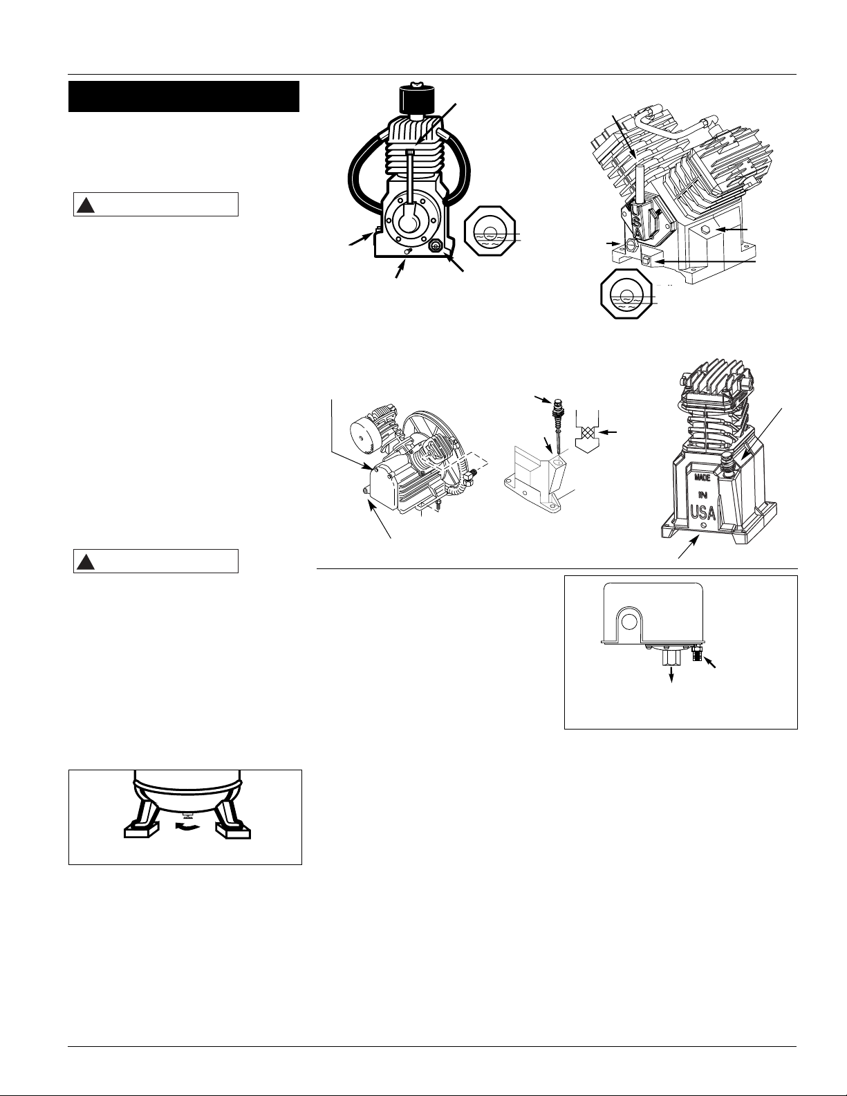
Todas las piezas que se mueven deben
estar protegidas con una tapa. Debe
colocarle todas las tapas al sistema eléctrico antes de encender el compresor.
LUBRICACION
ESTA
UNIDAD
NO TIENE ACEITE. Antes de utilizar el
compresor, llene la caja del cigüeñal. Use
aceite para compresores y siga las
instrucciones enumeradas en de la tabla
en “el Manual de Repuestos.”
Puede haber residuos de aceite en el
cabezal que dejarían una capa en el
vidrio del medidor visual, sin embargo,
no hay suficiente aceite para operar la
unidad. Llene el cabezal utilizando
aceite para compresores de aire IS0100.
Este aceite, cuyo número de pieza es
ST126700AV, es un aceite sin detergente y de viscosidad sencilla.
Igualmente puede utilizar aceite Mobil
1
®
5W30 ó aceite sintético 10W30.
Vierta el aceite sólo por el orificio de
lubricación. Si vierte el aceite por
cualquier otro orificio la unidad expulsará aceite tan pronto comience a funcionar. Sólo llene el cabezal hasta el
centro del medidor visual o hasta la
raya superior de la varilla para medir
aceite (Vea la Figura 5).
Si utili-
za
cualquier otro tipo de aceite podría disminuir la duración del cabezal y dañar las
válvulas.
PERIODO DE USO INICIAL RECOMENDADO
La primera vez que vaya a utilizar el
compresor, debe dejarlo funcionar continuamente durante una hora, para permitir que los anillos de los pistones se
fijen adecuadamente.
1. Abra la llave de drenaje del tanque y
deje que el compresor funcione
durante 60 minutos (Vea la Figura 6).
2. Apague el compresor y cierre la llave
de drenaje. El compresor está listo
para funcionar.
Si el compresor se utiliza bajo condiciones
húmedas por períodos cortos, la humedad
se condensará en la caja del cigüeñal y
ocasionará que el aceite luzca cremoso. El
aceite contaminado por el agua no le
proveerá la lubricación adecuada y lo
debe cambiar inmediatamente. Si usa
21 Sp
Serie De Hierro Colado
aceite contaminado, los cojinetes, pistones, cilindros y anillos se dañarán y
estos daños no están cubiertos por la
garantía. Para evitar la condensación de
agua en el aceite, periódicamente utílice
el compresor con una presión de más o
menos 10,34 bar. Para hacerlo, abra la
llave de drenaje, la válvula de aire conectada al tanque, o la manguera. Deje que
el cabezal funcione por una hora en estas
condiciones por lo menos una vez a la
semana, o con más frecuencia, en caso
de que el problema ocurra.
IMPORTANTE: Cámbiele el aceite
después de 50 horas de operación.
PRESOSTATO, ARRANQUE - PARO
NOTA: La presión máxima de trabajo de
este compresor es 12,07 bar. Nunca
exceda esta presión en ninguno de los
controles de los componentes.
El compresor se enciende y se apaga
según los valores fijados en el presostato. El presostato se debe conectar a un
motor de arranque mágnetico que controla el motor eléctrico. El sistema de
desfogue del presostato es una válvula
pequeña por la cual sale el aire para permitir que el motor arranque fácilmente
(Vea la Figura 7).
FUNCIONAMIENTO CONTINUO
Para utilizar este compresor en forma
continua le debe instalar una válvula de
carga separada, por ejemplo, una válvula
Genie entre el cabezal y el tanque.
Igualmente, debe desconectarle la válvula de chequeo original.
RESPIRADOR DE LA CAJA DEL
CIGÜEÑAL
Durante condiciones severas de funcionamiento o al encenderlo por
primera vez, podría crearse una acumulación de aceite en el orificio del respirador de la caja del cigüeñal. Ésto es
nornal y disminuirá con el uso, ya que
los anillos se fijarán.
Tapa del
respiradero
Tapón del
orificio de
lubricación
Tapon del
drenaje del aceite
Medidor visual
Lleno
Bajo
Lleno
Bajo
Tapa del
respiradero
Tapon del
orifico para
drenar del
aceite
Tapón del
orificio de
lubricación
Medidor
visual
Funcionamiento (Con’t)
Figura 6 - Para abrir la llave de drenaje
Orificio de drenaje lateral
Drenaje
Figura 5
Figura 7 - Presotato
Sistema de
desfogue
Hacia la presión
del tanque
Varilla para medir
el aceite y Orificio
de lubricación
Varilla para medir
el aceite y Orificio
de lubricación
Respirado para
la varilla para
medir el aceite
Añada aceite
Línea,llenhasta aquíes
Bajo de aceite
!
PRECAUCION
!
PRECAUCION
Breather
Cap
Full
Oil
Fill Plug
Oil Drain Plug
Sight Gauge
Low
Dipstick
Breather
Add Oil
Breather
Cap
Oil
Fill Plug
Sight
Gauge
Max
Low
Full
Low
Fill
Line
Oil
Drain
Plug
Unloader
To tank pressure
Page 22

BANDAS
Apague
el compresor, cerciórese de que el interruptor
no se pueda activar y después libere la
presión del tanque, para evitar que la
unidad se mueva sin previo aviso.
Chequée la tensión de las bandas cada 3
meses. Ajuste la tensión de las bandas para
permitir una deflección de 0,9 a 1,2 cm
(3/8 - 1/2”) al ejercer una presión normal
con el dedo. Igualmente, debe alinear las
bandas usando como referencia un objeto
recto que toque el volante y dos puntos
del borde a ambos lados del volante. Las
bandas deben estar paralelas a esta línea
recta de referencia (vea la Figura 9). Las
distancias A, B y C deben ser iguales para
asegurar que las bandas estén alineadas
adecuadamente.
Las ranuras en la base le
permiten mover el motor, en ambas
direcciones, para ajustar la tensión de las
bandas.
ALMACENAMIENTO
Si necesita almacenar el compresor por
un período corto, cerciórese de colocarlo
en una posición normal en un área fría y
bien protegida.
Compresores De Aire
Desconecte el cordón eléctrico,
amárrelo y aléjelo del tomacorrientes, después libere toda la presión
del tanque antes de tratar de instalar el
compresor, darle servicio, moverlo de
sitio o darle cualquier tipo de mantenimiento.
Para mantener el funcionamiento eficiente del sistema del compresor,
chequée el filtro de aire y mida el nivel
del aceite antes de cada uso. La válvula
de seguridad ASME también se debe
chequear a diario (Vea la Figura 8). Hále
el anillo de la válvula de seguridad y
déjelo que regrese de nuevo en su posición original. Esta válvula automáticamente li-bera el aire del tanque, si la
presión excede el nivel máximo fijado de
fábrica. Si hay una fuga de aire después
que ha soltado el anillo, o si la válvula
está atascada y no la puede activar con
el anillo, deberá reemplazar la válvula
de seguridad ASME.
Nunca
trate de
modificar las válvulas de sequridad
ASME.
TANQUE
¡Nunca trate de reparar o modificar el tanque! Si lo suelda, taladra o modifica de cualquier otra manera, el tanque se debilitará y se podría
dañar al romperse o explotar. Siempre
remplace los tanques desgastados, rotos
o dañados.
Drene el
líquido
del tanque diariamente.
El tanque se debe inspeccionar cuidadosamente por lo menos una vez al
año. Cerciórese de que no haya ranuras
en las soldaduras. De haberlas, libere la
presión del tanque inmediatamente y
reemplácelo.
LUBRICACION DEL COMPRESOR
Vea la sección de Funcionamiento Añádale
aceite al cabezal cuando sea necesario.
Debe cambiar el aceite y el filtro cada 3
meses o después de 500 horas de funcionamiento; lo que ocurra primero. Sólo
los cabezales lubricados a presión tienen
un filtro de aceite.
FILTRO DE AIRE
Nunca utilice el cabezal del compresor
sin instalarle el filtro de la entrada de
aire o con un filtro obstruído. Use aire
comprimido para limpiar el filtro. No
lave ni lubrique el elemento del filtro. Si
no puede limpiarlo con aire comprimido,
deberá reemplazarlo. Si utiliza el compresor con el filtro sucio, podría aumentar el consumo de aceite y la contaminación con aceite del aire expulsado.
SISTEMA DE ENFRIAMIENTO
INTERNO
Las altas
del sistema de enfriamiento interno son afiladas, use siempre guantes y tenga
mucho cuidado cuando vaya a limpiar o
trabajar cerca de ellas.
Semanalmente, chequée el sistema de
enfriamiento para cerciorarse de que
todas las conexiones estén bien apretadas. Use aire para limpiarle las aletas
al sistema.
COMPONENTES
Mensualmente, apague la unidad y
limpie la culata del cilindro, el motor, las
aletas del ventilador, las líneas de aire,
el sistema de enfriamiento interno y el
tanque con aire a baja presión.
22 Sp
Mantenimiento
MANTENIMIENTO
Servicio Necesario
Diaria- Semanal- Mensual- Trimestralmente mente mente mente
Borde recto (Base)
Compresor de aire
Polea del
motor
Tornillo de adjuste
Figura 9
Chequée la válvula de seguridad
Drene el tanque (Vea la Figura 6)
Mida el nivel de aceite
Limpie o cambie el filtro de aire
Chequée el sistema de
enfriamiento interno (sólo
en los compresores de 2 etapas)
Limpie los componentes
Chequée la tensión de las bandas
Cambie el aceite (Vea la Figura 5)
Cambie el filtro de aceite
(Solo en los modelos de lubricacion a presion)
Figura 8
Volante
!
ADVERTENCIA
!
PELIGRO
!
PELIGRO
AVISO
AIR COMPRESSOR
FLYWHEEL
!
ADVERTENCIA
MOTOR
SETSCREW
STRAIGHTEDGE
AB
!
ADVERTENCIA
MOTOR
DRIVE
PULLEY
C
Page 23

23 Sp
Serie De Hierro Colado
Guía de diagnóstico de averías
Problema Posible(s) Causa(s) Acción a tomar
1. Voltaje bajo o nulo
2. La bobina del motor tiene un cortocircuito o está
desactivada
3. La válvula de chequeo o la válvula de desfogue
están dañadas
4. El presostato está dañado - los contactos no cierran
1. El presostato está fijado a una presión muy alta
2. La válvula de chequeo está dañada
3. Los fusibles o calentadores del motor de arranque
magnético no son adecuados
4. El motor está dañado
5. Algún cable está desconectado
1. La polea, el volante, la banda, la tapa de las bandas,
etc está floja
2. Le falta aceite a la caja del cigüeñal
3. La base del compresor está floja
4. La válvula de chequeo está dañada
El agua se está condensando en la caja del cigüeñal
debido a la alta humedad
1. Cerciórese de que haya un problema
2. La entrada de aire está restringida
3. Está usando un aceite de viscosidad inadecuada
4. Los anillos del pistón están dañados
5. Hay fugas de aceite
6. El cilindro está rayado
1. Exceso de agua en el tanque
2. El clima es calido y húmedo
La válvula de entrada de la primera etapa está dañada
(en los compresoresde 2 etapas)
La válvula de entrada está dañada (en los compresores
de una etapa)
1. Se requiere demasiado aire
2. Hay fugas u obstrucciones en las mangueras o
tuberías
3. Las bandas están desajustadas
1. La válvula de chequeo está desgastada
2. Chequée todas las conexiones a ver si están
bien apretadas
3. Chequée el tanque a ver si está partido o tiene orificios
1. La polea está desalineada
2. Las bandas están muy apretadas o muy flojas
1. El filtro de aire está dañado
2. El empaque de la culata del cilindro está dañada
3. La válvula de entrada/salida está desgastada/dañada
4. Hay fugas de aire
Exceso de agua en el tanque
1. El presostato está fijado incorrectamente
2. La válvula de seguridad ASME está dañada
3. Los contactos del presostato se soldaron
La válvula de chequeo está dañada
La válvula de desfogue del presostato está dañada
1. El empaque de la culata o el empaque del ensamblaje de la placa de la válvula están deterioradas
2. La válvula no está bien instalada
3. La válvula de seguridad está dañada
La válvula de seguridad del tanque está dañada
1. Chequée con un voltimetro, chequée el relai de sobrecarga del motor de
arranque magnético o el interruptor del motor. Si alguno de estyos
interruptores se desconectan constantemente, ubique el problema y corríjalo. Vea el próximo paso
2. Reemplace el motor
3. Reemplace la válvula de chequeo o de desfogue
4. Repare o reemplace el presostato
1. Ajústelo o reemplácelo
2. Limpie o reemplace la válvula dañada
3. Cerciórese de que los fusibles o calentadores sean los adecuados
4. Reemplace el motor
5. Revise todas las conexiones del sistema eléctrico
1. Apriételos
2. Chequée los cojinetes a ver si están dañados, póngale aceite
3. Nivele la base y apriétela o colóquela sobre unas almohadillas
4. Reemplace la válvula de chequeo
Conecte la entrada de aire a una fuente de aire menos húmedo. Deje que el
cabezal funcione continuamente por 1 hora
1. Chequée a ver si hay problemas de contaminación del aceite: pruebe el
aire expulsado o mida el consumo del aceite de la caja del cigüeñal
2. Limpie o reemplace el filtro de aire
3. Drene el aceite. Póngale aceite de viscosidad adecuada
4. Reemplace los anillos
5. Apriete los pernos, reemplace los empaques o anillos en o
6. Reemplace el cilindro
1. Drene el tanque
2. Compre un secador
Reemplace la válvula
1. Limite el uso del aire
2. Chequée las mangueras y tuberías a ver si hay fugas o restricciones
3. Apriete las bandas
1. Reemplace la válvula de chequeo
No desmonte la valvula de
retencion con aire en el tanque
2. Apriételos
3. Reemplace el tanque. Nunca repare un tanque dañado
1. Debe alinear la polea del motor
2. Ajuste la tensión
1. Limpie o reemplace el elemento del filtro
2. Cambie el empaque
3. Instale un ensmablaje nuevo de la placa de la válvula
4. Apriete las conexiones
Drene el tanque, chequée la velocidad. Vea la tabla de rendimiento
1. Disminuya la presión (12,07 bar máximo en la unidad de dos etapas ó 9,31 bar
en la unidad de una etapa) (Vea la sección Funcionamiento)
2. Reemplace la válvula de seguridad ASME
3. Reemplace el presostato
Reemplace la válvula de chequeo si la válvula de desfogue se activa constantemente
Reemplace el presostato si la unidad no expulsa aire por un período corto
cuando la apaga
1. Reemplace la placa de la válvula y los empaques
2. Reemplace la placa de la válvula y los empaques
3. Reemplace la válvula de seguridad
Reemplace la válvula de chequeo
El motor hace ruido y funciona lentamente o no funciona
El sistema de encendido se
desactiva constantemente o
los fusibles se queman
constantemente
Hace mucho ruido al funcionar
El aceite luce cremoso
Consumo excesivo de aceite
o presencia de aceite en las
líneas de aire
Agua en el aire expulsado
Aire sale por el orificio de
entrada
Presión insuficiente
El tanque no mantiene la
presión cuando el compresor está apagado y la válvula de cierre está cerrada
Desgasto excesivo de las
bandas. (Es normal que se
desboronen un poco al
principio. Cuando se desgastan las bandas se separan en capas)
El tanque se demora en
alcanzar la presión deseada
La presión en el compresor
aumenta demasiado rápido
La válvula de seguridad se
abre mientras el compresor
está funcionando
El presostato expulsa aire
continuamente pos la
válvual de desfogue
La válvula de desfogue del
presostato no libera aire
cuando la unidad se apaga
La válvula de seguridad,
inter-etapas, se activa mientras la unidad está funcionando
La válvula de seguridad,
inter-etapas, se activa cuando la unidad se apaga
!
PELIGRO
Page 24

Compresores De Aire
Serie De Hierro Colado
Garantía Limitada
1. DURACION: A partir de la fecha de compra por el comprador original tal como se especifica a continuación: tres años o cinco años, según el
modelo.
2. QUIEN OTORGA ESTA GARANTIA (EL GARANTE: Maxus, 100 Production Drive, Harrison, Ohio 45030, Telephone:1-800-543-6400.
3. BENEFICIARIO DE ESTA GARANTIA (EL COMPRADOR): El comprador original (que no sea un revendedor) del producto Maxus.
4. PRODUCTOS CUBIERTOS POR ESTA GARANTIA: Todos los compresores de aire Maxus, herramientas o accesorios neumáticos
suplementarios suministrados o fabricados por el Garante.
5. COBERTURA DE LA GARANTIA: Los defectos de material y fabricación que ocurran dentro del período de validez de la garantía.
6. LO QUE NO ESTA CUBIERTO POR ESTA GARANTIA:
A. LAS GARANTIAS IMPLICITAS, INCLUYENDO LAS GARANTIAS DE COMERCIALIDAD Y CONVENIENCIA PARA UN FIN PARTICULAR, TAL
COMO SE ESPECIFICA EN EL PARRAFO DE DURACION. Si este producto es empleado para uso comercial, industrial o para renta, la
garantía será aplicable por noventa (90) días a partir de la fecha de compra. La garantía para los compresores de aire de cuatro
cilindros de una o dos etapas no está limitada a noventa (90) días al usarse en labores comerciales o industriales. En algunos estados no
se permiten limitaciones a la duración de las garantías implícitas, por lo tanto, en tal caso esta limitación no es aplicable.
B. CUALQUIER PERDIDA DAÑO INCIDENTAL, INDIRECTO O CONSECUENTE QUE PUEDA RESULTAR DE UN DEFECTO, FALLA O
MALFUNCIONAMIENTO DEL PRODUCTO CAMBELL HAUSFELD. En algunos estados no se permite la exclusión o limitación de daños
incidentales o consecuentes, por lo tanto, en tal caso esta limitación o exclusión no es aplicable.
C. Cualquier falla que resulte de un accidente, abuso, negligencia o incumplimiento de las instrucciones de funcionamiento y uso
indicadas en el (los) manual(es) que se adjunta(n) al producto.
D. El servicio al producto antes de la venta, tales como ensamblaje, aceite o lubricantes y ajustes.
E. Los artículos o servicio normalmente requeridos para el mantenimiento del producto, tales como pero no limitados a bandas y
presostatos.
F. Los artículos o servicios normalmente requeridos para el mantenimiento del producto, tales como lubricantes, filtros y empaques.
G. Las piezas para motores eléctricos o de gasolina están específicamente excluídos de la cobertura de esta garantía limitada. Éstos deben ser
enviados por el comprador al fabricante original o a los centros de servicio autorizados por el fabricante para que se les den servicio.
H. Artículos adicionales no cubiertos por esta garantía:
1. Todos los compresores
a. Cualquier componente dañado durante el envío o cualquier daño ocasionado por haber instalado u operado la unidad bajo
condiciones contrarias a lo indicado en las instrucciones para instalar u operar la unidad.
b. Daños del cabezal o las válvulas ocasionados por la lluvia, humedad excesiva o agentes corrosivos
c. Daños de apariencia que no afecten el funcionamiento del compresor.
d. Tanques oxidados, incluyendo pero no limitado al óxido debido al drenaje inadecuado.
e. Los motores eléctricos y válvulas de chequeo después del primer año de propiedad.
f. Llaves de drenaje.
g. Capacitadores del motor.
h. Otros artículos no enumerados pero considerados piezas de desgaste general.
2. Compresores lubricados
a. Daños del cabezal o las válvulas debidos al uso de aceites no especificados.
b. Daños del cabezal o las válvulas debidos a cualquier contaminación del aceite o por no haber seguido las instrucciones de
lubricación.
3. Compresores con bandas/ de accionamiento directo/ motores de gasolina
a. Bandas
b. Daños de los anillos debido al mantenimiento inadecuado del filtro.
c. Ajustes manuales de los instrumentos de carga/descarga y válvula de estrangulación.
7. RESPONSABILIDADES DEL GARANTE BAJO ESTA GARANTIA: Reparar o reemplazar, como lo decida el Garante, los productos o
componentes defectuosos dentro del período de validez de la garantía.
8. RESPONSABILIDADES DEL COMPRADOR BAJO ESTA GARANTIA:
A. Presente los records de mantenimiento para reclamar sus derechos bajo esta garantía.
B. Los productos portátiles o componentes deben entregarse o enviarse al centro de servicio autoirzado de Maxus más
cercano.
C. Tener cuidado al utilizar el producto, tal como se indica(n) en el (los) manual(es) del propietario.
9. CUANDO EFFECTUARA EL GARANTE LA REPARACION O REEMPLAZO CUBIERTO BAJO ESTA GARANTIA:
A. La reparación o reemplazo dependerá del flujo normal de trabajo del centro de servicio y de la disponibilidad de repuestos.
B. Si el comprador no recibe resultados satisfactorios en el Centro de Servicio a Clientes de Maxus. (Ver Párrafo 2).
Garantía Limitada es válida sólo en los Estados Unidos y Canada y le otorga derechos legales específicos. Usted también podría tener otros
derechos que varían de un Estado a otro o de un país a otro.
 Loading...