

Maxum 3100 SCR Owner's Manual


Engine Serial Numbers:
Port______________________________________________________________
Starboard_________________________________________________________
Hull Identification Number: __________________________________________
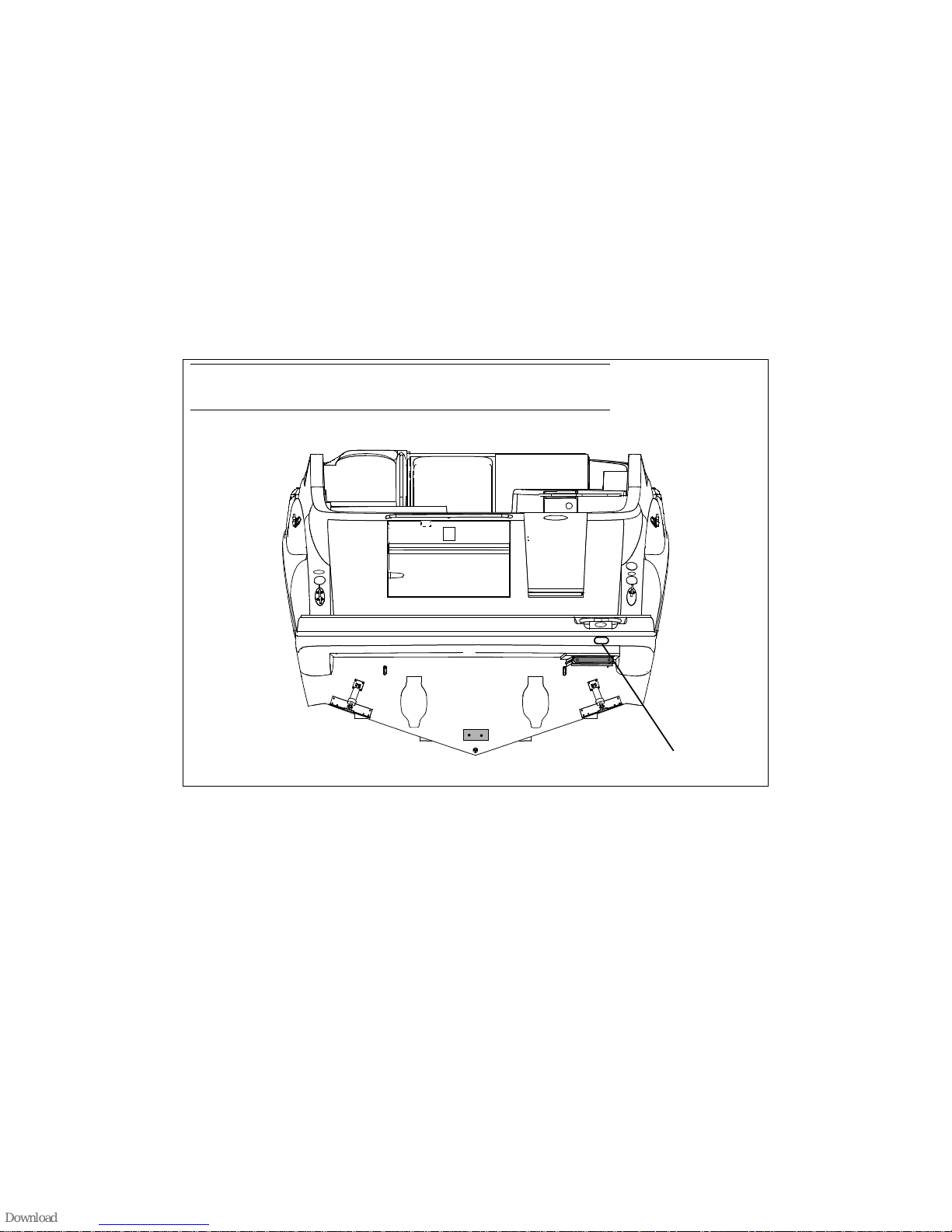
The Hull Identification Number (HIN) is located on the starboard side of the swimstep. Be sure to record the HIN in
the space provided above and refer to the HIN for any correspondence or orders.
Record the HIN and the engine serial number in the space provided above.
Please refer to the HIN for any correspondence or orders.
HIN LOCATION
© 2002 Maxum Marine Technical Publications. All rights reserved.
No part of this publication may be reproduced, stored in any retrieval system, or transmitted in any form by any means, electronic, mechanical, photocopying,
recording or otherwise, without prior written permission of Maxum. Printed in the U.S.A.
General Notes
The material in this document is for information only and is subject to change without notice. While reasonable efforts have been made in the preparation of this
document to assure its accuracy, Maxum assumes no liability resulting from errors or omissions in this document, or from the use of information contained herein.
Due to our commitment to product improvement, Maxum reserves the right to make changes in the product design, specifications and equipment at any time without notice or obligation. Illustrations and/or photos may show optional equipment. All Maxum products meet or exceed USCG (Unites States Coast Guard) and/or
NMMA (National Marine Manufacturer’s Association) construction standards. Manufactured with 1,1,1 Trichloroethane, a substance which harms public health
and environment during the manufacturing process by destroying ozone in the upper atmosphere.
Proprietary Rights
This document discloses s ub ject mat t er in which Maxum has proprietary rig ht s. Th e inf or m atio n an d de sign disc l o s ed herein were originated by and are the property of Maxum. Neither receipt nor possession thereof confers or transfers any right to reproduce, copy, alter or disclose the document or any part thereof, any
information contain ed therein, or to construct boats or any item from it, except by written permiss io n f r om or written agreement with Maxum. This document is to
be returned upon request to Maxum.

CONTENTS
CHAPTER 1: WELCOME ABOARD!
1 Dimensions and Tank Capacities
1 Layout View
1 Dealer Service
1 About Your Limited Warranty
2 Boating Experie nce
2 Safety Standards
2 Engine & Accessories Guidelines
3 Qualified Maintenance
3 Structural Limitations
3 Special Care For Moor ed Boats
3 Sacrificial Anodes (Zincs)
4 Carbon Monoxide (C O)
5 Sources of CO
5 Carbon Monoxide Alarm System
5 What To Do If Carbon Monoxide
Is Detected
6 Boat Liftin g
CHAPTER 2: LOCATIONS
7 Exterior Views
7 Hull views
8 Deck Views
10 Helm
11 Component Locations
CHAPTER 3: PROPULSION &
RELATED SYSTEMS
12 Engines
12 Engine Room Ventilation System
13 Fire Suppression System (If Equipped)
14 Fuel System
14 Diagrams
15 Fuel Fill and Vent
15 Fuel Filters
15 Anti-siphon Valve
CHAPTER 4: CONTROLS
16 Steering
16 Shift/Throttle
16 Power Trim and Tilt
17 Trim Tabs
18 Bow Thruster (If Equipped)
CHAPTER 5: NAVIGATION &
COMMUNICATIONS EQUIPMENT
19 VHF Radio
19 Compass
19 Depth Finder
19 Global Positioning System (G PS)
(If Equipped)
CHAPTER 6: PLUMBING
20 Bilge Pumps
21 Autofloat Switches
22 Seawater Systems
22 Seacocks
22 Seawater Strainers
23 Freshwater System
24 Trans om Shower
24 Water Heater
24 City Water Inlet
25 Drain Systems
25 Deck Drains
26 Gray Water Drain System (If Equipped)
26 Sump Box Cleaning
26 Sump System Winterization
27 Gray Water Recovery System
(If Equipped)
28 Marine Head With Hol ding Tank
28 Electric Flush Marine Head (If Equipped)
29 VacuFlush (If Equipped)
30 Macerator (If Equipped)

CHAPTER 7: DECK EQUIPMENT
CHAPTER 12: ELECTRICAL SYSTEM
31 Canvas
32 Windlass (If Equipped)
32 Windshield Wiper
32 Cleats and Tow Eyes
CHAPTER 8: APPLIANCES &
ENTERTAINMENT SYSTEMS
33 Refrigerator
33 Electric Stove (If Equipped)
34 Alcohol/Electric Stove (If Equipped)
35 Audio & Visual Equipment
35 Dockside Cable TV & Telephone
(If Equipped)
CHAPTER 9: CONVERTIBLE SEATS,
BEDS, & TABLES
36 Dinette/Berth
37 Aft Cockpit Table/Sunlounge
CHAPTER 10: LIGHTS
38 Care and Maintenance
38 Navigat i on Lights
38 Interior & Exterior Lights
38 Spotlight (If Equipped)
40 12 Volt DC System
40 Batteries
41 Alternator
41 Battery Charger
41 12 Volt Accessory Outlets
41 Fuses and Circuit Breakers
42 Battery Switches
43 120 Volt AC System
44 Shore Power
46 Connecting To Shore Power
47 Transfer Switch (If Equipped with
Dual Shore Power)
48 Generator (If Equipped)
49 Gas Generator
51 Dies el Generator
53 Electrical Routings
53 Deck Electrical Harness
53 Hull Electrical Harness
54 Battery System
54 Bow Thruster Battery System
(If Equipped)
55 120 Volt AC System
56 Bonding Harness
57 Wire Diagrams
57 Engine Electrical System
58 DC Electrical System
59 AC Electrical System
60 Connector List
CHAPTER 11: HEATING &
AIR CONDITIONING
39 Air Conditioning System (If Equipped)
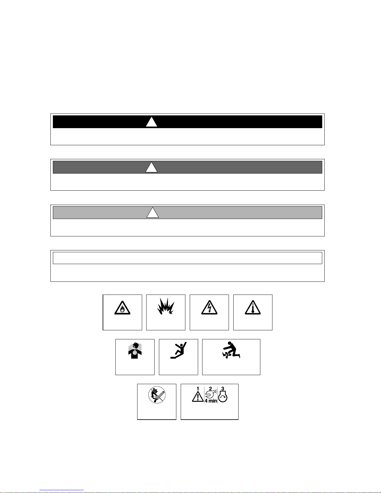
Hazard Boxes & Symbols
The hazard boxes and symbols shown below are used throughout this supplement to call attention to potentially dangerous situations which could lead to either personal injury or product damage. Read ALL warnings carefully and
follow all safety instructions .
!
DA N GE R!
This box alerts you to i mmediate hazards whic h WILL cause se vere pe rsonal in jury or death if
the warning is ignored.
WARNING!
!
This box alerts you to haza rds or unsafe practices which COULD result in sever e pe rsonal
injury or death if the warning is ignored.
!
CAUTION!
This box alerts you to hazards or unsafe practices which COULD result in minor personal
injury or cause product or property damage if the warning is ignored.
NOTICE
This box calls attention to installati on, operation or maintena nce informat ion, which is important to proper operation but is not hazard related.
FIRE
HAZARD!
CO POISONING
HAZARD!
EXPLOSION
HAZARD!
NO OPEN
FLAME!
ELECTRICAL
HAZARD!
FALLING
HAZARD!
RUN BILGE BLOWERS
FOR 4 MINUTES!
HOT
HAZARD!
ROTATING
PROPELLER HAZARD!
CHAPTER 1: WELCOME ABOARD!
This Owner’s Manua l Supplement provides specific informati on about your boat that is not covered in the Cruiser &
Yacht Owner’s Manual. Please study the Cruiser & Yacht Owner’s Manual and this supplement carefully. Keep the
Cruiser & Yacht Owner’s Manual and this supplement on your boat in a secure, yet readily available place.
Dimensions and Tank Capacities
1
Overall
Length
30' 9" 12' 9" 9' 10" 2' 1" 3' 5" 150 35 30
Bridge
Clearance
Beam
Draft
(Drive Up)
Draft (Drive
Down)
Fuel Capacity
(gal.)
Freshwater
Capacity (gal.)
Waste Holding
Tank Capacity (gal.)
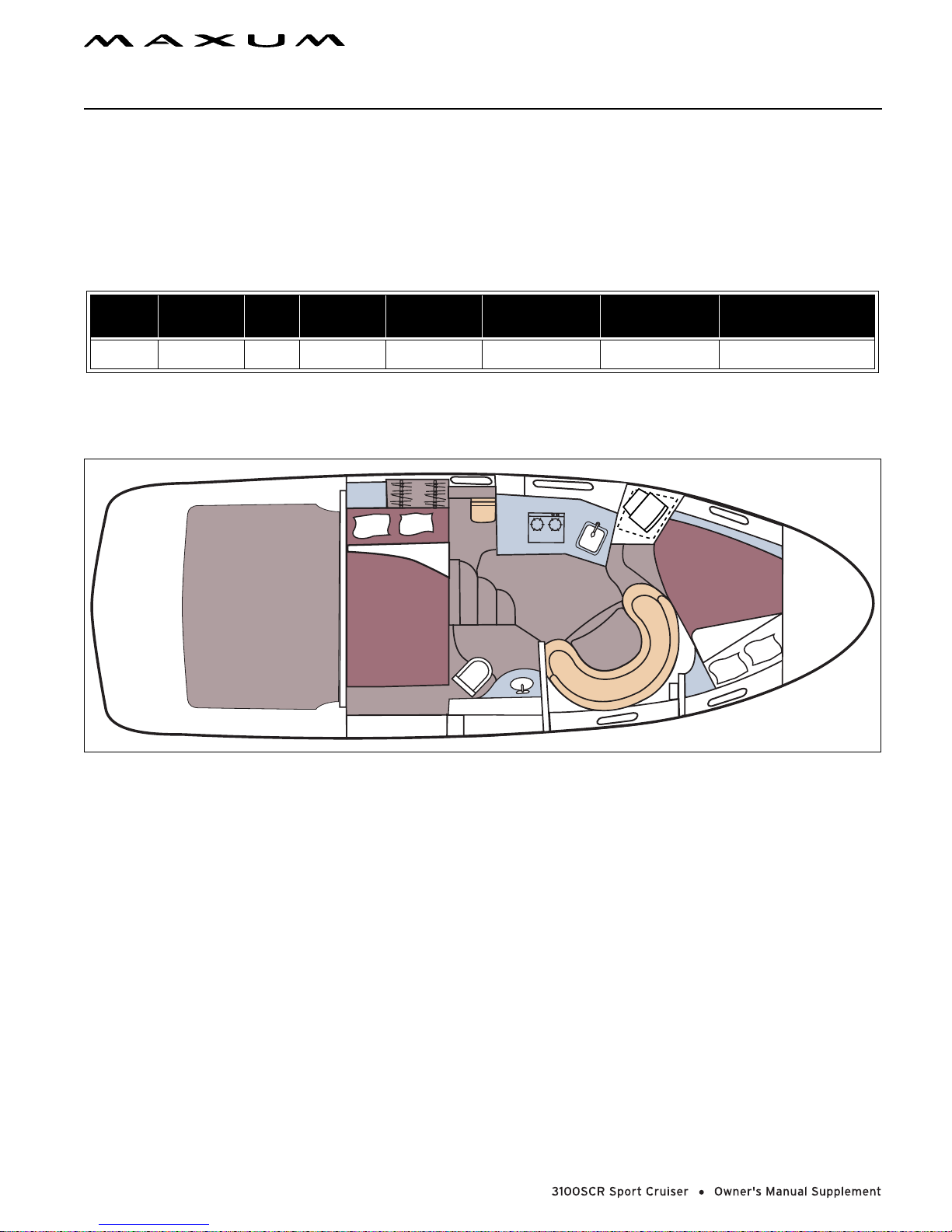
Layout View
Dealer Service
• Ask your dealer to explain all systems before taking delivery of your boat.
• Your dealer is your key to service.
• Contact your dealer if you have any problems with your new boat.
• If your dealer cannot help, call our customer service hotline: 360-435-8957 or send us a FAX: 360-403-4235.
• Buy replacement parts from any authorized Maxum dealer.
About Your Limited Warranty
• Maxum offers a Limited Warranty on each new Maxum purchased through an authorized Maxum dealer.
• A copy of the Limited Warranty wa s included in y our owner’s packet.
• If you did not receive a copy of the Limited Warranty, please contact your dealer or call 360-435-8957 for a copy.
2 CHAPTER 1: WELCOME ABOARD!
Boating Experience
WARNING!
!
CONTROL HAZARD! A qualified operator must be in control of the boat at all times. DO NOT
operate your boat while under the influence of alcohol or drugs.
If this is your first boat or if you are changing to a type of boat you are not familiar with, for your own comfort and
safety, obtain handling and operating experience before assuming command of the boat.
Take one of the boating safety classes offered by the U.S. Power Squadrons or the U.S. Coast Guard Auxiliary. For
more course information, including dates and locations of upcoming classes, contact the organizations directly:
• U.S. Power Squadrons: 1-888-FOR-USPS (1-888-3 67-8777) or on the Internet at: http://www.usps.org
• U.S. Coast Guard Auxiliary: 1-800-368- 5647 or on the Internet at: http://www.cgaux.org
Outside the United States, your selling dealer, national sailing federati on or loc al boat club can advise you of local
sea school s or co m p etent instructor s.
Safety Standards
!
PERSONAL SAFETY HAZARD! DO NOT allow anyone to ride on parts of the
boat not designated for such use. Sitting on seat backs, lounging on the forward
deck, bow riding, gunwale riding or oc cupying the transom platform while
underway is especially hazardous and will cause personal injury or death.
!
PERSONAL SAFETY HAZARD! ALWAYS secure the anchor and other loose obje cts before getting underway. The anchor and other it ems that are not properl y secured can c ome loose when
the boat is moving and cause pe rsonal injury or death.
Your boat’s mechanical and electrical systems were designed to meet safety standards in effect at the time it was
built. Some of these standards were mandated by law, all of them were designed to insure your safety, and the safety
of other people, vessels and property.
In addition to this owner’s manual suppl ement , please read the Cruiser & Yacht Owner’ s Manual and all acces-
sory instructions for important safety standards and haza rd information.
DA N GE R!
DANGER
DA N GE R!
DANGER
Engine & Accessories Guidelines
NOTICE
When storing your boat please refer to your engine’s operation and maintenance ma nuals.
Your boat’s engines and accessories w ere selected to provide optimum pe rformance and ser vice. Installing dif fere nt
engines or other accessories may cause unwanted handling characteristics. Should you choose to install different
engines or to add accessories that will affect the boat’s running tri m, have a n expe ri enced marine technician perf orm
a safety inspection and handling test before operating your boat again.
Certain modifications to your boat can result in cancellation of your warranty protection. Always check with
your dealer before making any modifications to your boat.
The engines and accessories installed on your boat come with their own operation and maintenance manuals. Read
and understand these manuals before using the engines and accessories.
CHAPTER 1: WELCOME ABOARD! 3
Qualified Maintenance
WARNING!
!
To maintain the integrity and safety of your boat, allow only qu al ified personnel to perform
maintenance on, or in any way modify: The stee ring syst em, propulsion system, engine co ntrol
system, fuel system, environmental cont rol system, electrical system or navigational system.
Failure to maint ai n you r boat’s systems (listed in the warning above) as designed c ould violate the laws in yo ur j ur isdiction and could expose you and other people to the danger of bodily injury or accidental dea th. Follow the instructions provided in the Cruiser & Yacht Owner’s Manual, this Owner’s Manual Supplement, the e ngine owner’s manual
and all accessory instruction sheets and manuals included in your boat’s owner’s packet.
Structural Limitations
The transom platform and bow platform are designed to be lightweight for proper boat balance. The load limit for
these platforms is 30 pounds per square foot, evenly distributed.
Special Care For Moored Boats
NOTICE
• To help seal the hull bottom and reduce the poss ibility of gelcoat blistering on moore d boats,
apply an epoxy barrier co ating, such a s INTERLUX, Interp rotect 200 0E/2001E. The barrier
coating should be covered with several coats of anti-fouling paint.
• Many states regulate the chemical cont ent o f bottom paints in order to meet environmental
standards. Check with your local deale r about recommended bottom paints, and about the
laws in effect in your area .
Whether moored in saltwater or freshwater, your boat will collect marine growth on i ts hull bottom. This wi ll detract
from the boat’s beauty, greatly af fect it s perfor mance and may damage the gelcoat . There are two methods of s lowing
marine growth:
• Periodically haul the boat out of the water and scrub the hull bottom with a bristle brush and a solution of soap
and water.
• The hull below the waterline may have anti-fouling paint applied by the factory. Occasionally you will need to repaint it with a good grad e of anti -fouling paint.
Sacrificial Anodes (Zincs)
NOTICE
Do not paint between the zinc and the metal surface it contacts and do not paint over the zincs .
Your boat is equipped with sacrifici al anodes (zincs) to protect underwat er me tal parts from excessive deter io ration.
Check the zincs regularly and repl ace them if they have deteriorat ed mo re than 70%.
There are many factors that affect the rate at which the zincs deteriorate, including:
• Water temper ature
• Salinity
• Water pollution
Stray elect rical current from the boat or dock may caus e complete deterioration in just a few weeks. If there is rapid
zinc deterioration, measure the electrolytic corrosion around your boat with a Corrosion Test Meter. If the zincs are
not bonded correctly, they will not provide protection.
4 CHAPTER 1: WELCOME ABOARD!
Carbon Monoxide (CO)
!
CARBON MONOX IDE POIS ONING HAZARD!
DA N GE R!
DANGER
Carbon monoxide gas (CO) is col orle ss, odorless, and extremely dangerous. All
engines, generators, and fuel bur ning appliance s produce CO as e xhaust. Dir ect and
prolonged exposure to CO will caus e BRAIN DAMAGE or DEATH.
Signs of CO poisoning include:
• Headache
• Nausea
• Dizziness
• Drowsiness
• CO poisoning causes a significant number of boating deaths each year.
• Called the "silent killer" , CO is an ext remely toxic, colorless, odor less and tasteless gas.
• Breathing CO blocks the abi lity of your blood to car ry oxygen.
• The effects are cumulative, even low levels of exposure can result in injury or death.
Factors increasing the effects of CO poisoning include:
• Age
• Smokers or people exposed to high concentrations of cigarette smoke
• Consumption of alcohol
• Lung disorders
• Heart problems
• Pregnancy
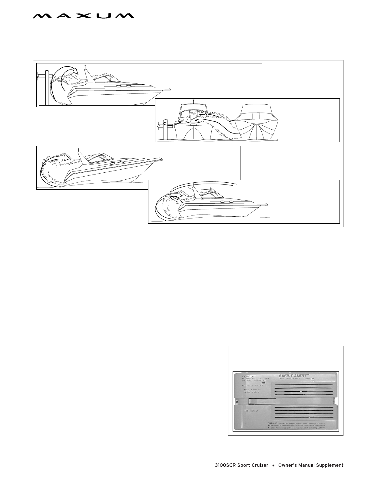
Sources of CO
Sources of CO include:
CHAPTER 1: WELCOME ABOARD! 5
a. Using engine s or genera-
tor when boat is moored
in a confined space.
b. Mooring close to
another boat that
is using its engin e,
generator or any
other CO source.
c. Running boa t with
trim angle of bow
too high.
d. Running boat without
through ventilation
(station wagon effect).
To correct stationary situations (a) and/or (b):
• Close all windows, portlights and hatches.
• If possible, move your boa t aw ay from the source of CO.
To correct running situations (c) and/or (d):
• Trim bow down.
• Open windows and canvas.
• When possible, run boat so that prevailing winds will help dissipate exhaust.
Immediately take corrective action if CO is detected or suspected (see, Carbon Monoxide Alarm System, below).
Carbon Monoxide Alarm Syst em
Your boat feat ures a carbon monoxide (CO) alarm system. Do not
disconnect the alarm system. Read and understand the manufacturer’s
instructions for your CO alarm system. If you did no t r eceive an instruc-
MARINE TECHNOLOGIES INC.
CARBON MONOXIDE ALARM - MODEL 60-541
(REPLACE AFTER TEN YEARS OF USE)
tion manual, call (800) 383-0269 and one will be mailed to you. If your
boat is not equipp ed with a carbon monoxide alarm, consider purchasing one from your dealer or marine supply store.
What To Do If Carbon Monoxide Is Detected
• Immediately ventilate and evacuate any enclosed spaces that are
occupied by people and reset your CO alarm.
• Immediately move anyone showing any symptoms of CO poisoning
into fresh air. See a doctor if any symptoms persist. If the person is
unconscious, immediately administer oxygen or CPR and call for
emergency help.
6 CHAPTER 1: WELCOME ABOARD!
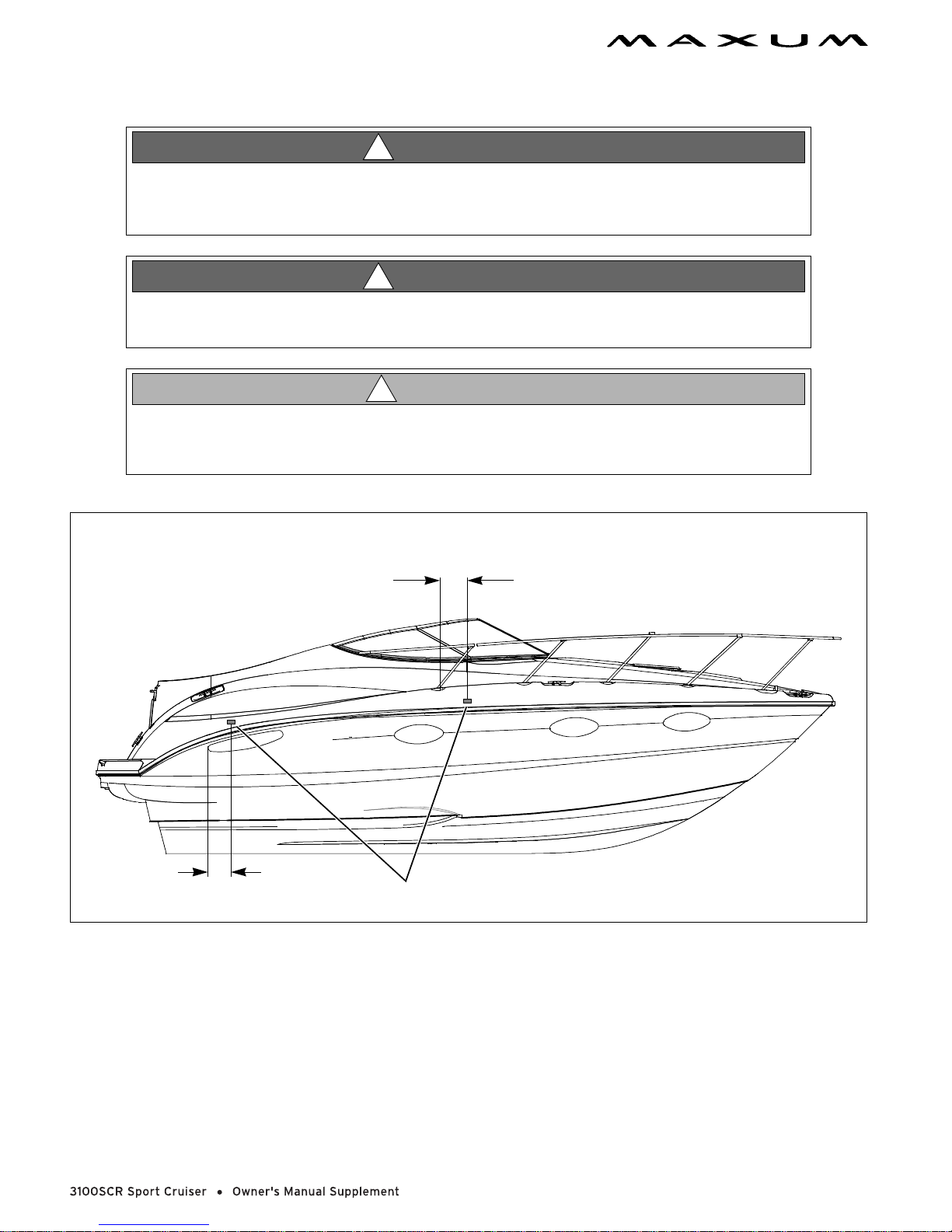
Boat Lifting
PERSONAL INJURY and /or PRODUCT or PROPERTY DAMAGE HAZARD!
• Lift slings may slip on the hull. Avoid serious injury or death by securing t he sli ngs together
before lifting.
PERSONAL INJURY and /or PRODUCT OR PROPERTY DAMAGE HAZARD!
• NEVER Lift the boat using the bow and stern eyes or the cleats.
PRODUCT or PROPERTY DAMAGE HAZARD!
• When lifting any boat, always use a spreader bar. The spreader bar must be equ al to the
width of the boat at the lifting point.
WARNING!
!
WARNING!
!
!
CAUTION!
"
16
"
14
LIFTING SLING LABELS (TYPICAL PORT & STARBOARD)
• Always follow the lift equipment’s instructions and requirements.
• Water in the bilge can shift and change the balance of the load.
• If water is present in the bilge, pump or drain the water out of the bilge areas before lifting your boat.
• When lifting your boat , always posi tion the l ifting sli ngs at the p ort and sta rboard sl ing label position s as shown in
the illustration above.

CHAPTER 2: LOCATIONS
Exterior Views
Hull views
TRANSOM
1
4533
2
7
1 STERN EYES (STRONG POINTS)
2 BOARDING LADDER
3TRIM TABS
1
1 BOW EYE (STRONG POINT)
2PORTLIGHTS
4 ZINC PLATE
5 BILGE DRAIN PLUG
PORT HULLSIDE
2
3 GENERATOR EXHAUST (IF EQUIPPED)
4 DECK DRAIN
STARBOARD HULLSIDE
34
1 2 3 4 6 7 8 9 10 11 12 135
1 DECK DRAINS
2 AFT BILGE PUM P DRAIN
3 FUEL VENT
4 WATER TANK VENT
5 HOLDING TANK VENT
6 WATER HEATER DRAIN
7 SINK DRAIN
8 GRAY WATER TANK DRAIN (IF EQUIPPED)
9 GRAY WATER TANK VENT (IF EQUIPPED)
10 AIR CONDITIONER DRAIN (IF EQUIPPED)
11 PORTLIGHTS
12 FORWARD BILGE PUMP DRAIN
13 ANCHOR LOCKER DRAIN

8 CHAPTER 2: LOCATIONS
Deck Views
FOREDECK
1 CLEATS (STRONG POINTS)
2 WINDLASS (IF EQUIPPED)
3 WINDLASS CONTROLS
(IF EQUIPPED)
MID-DECK
7
3
5
4
1
2
4 ANCHOR ROLLER
5 ANCHOR DEAD END
6 SPOTLIG H T (IF EQUIPPED)
1
9
1
9
8
1
6
7 ANCHOR LOCKER DRAIN
8 HIDDEN HORN
9 NAVIGATION LIGHTS
1 ALL AROUND LIGHT
2 RADAR (IF EQUIPPED)
3 TV ANTENNA (IF EQUIPPED)
4 WIPER
2
3
4
5
6
7
8
5 VENTILATION HATCHES
6 GRAB RAILS
7 BOW RAIL
8BOW HATCH
CHAPTER 2: LOCATIONS 9
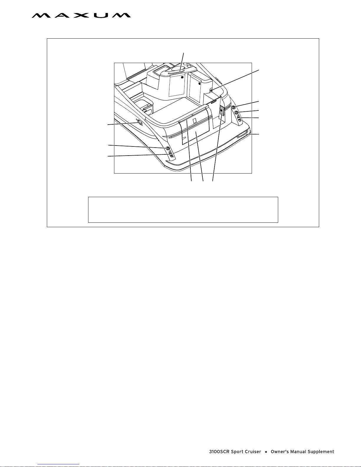
1
AFT DECK
2
3
2
1 GRAB RAIL
2 CLEAT (STRONG POI N T)
3 WATER FILL DECK FITTING
4 COURTESY LIGHT
4
6
7
2
1
8
1
5
5 TRANSOM SHOWER
6 FUEL FILL DECK FITTING
7 WASTE PUMP-OUT DECK FITTING
8 TRANSOM STORAGE BOX
10 CHAPTER 2: LOCATIONS
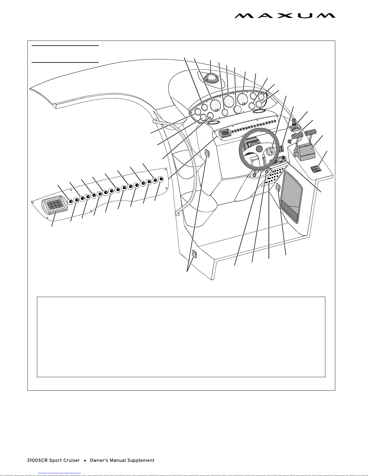
Helm
NOTE: TYPICAL HELM LAYOUT SHOWN
ACTUAL LAYOUT MAY VARY DEPENDING
ON ENGINE AND ACCESSORY OPTIONS
4
5
6
7
8
9
5
4
1
3
2
10
11
12
13
24
24
23
22
21
24
23
23
28
29
1 VOLTMETER
2 TEMP GAUGE
3OIL GAUGE
4 POWER TRIM & TILT GAUGE
5 TACHOMETER
6 COMPASS
7 FUEL GAUGE
8 SPEEDOMETER
9 DEPTH SOUNDER
10 SPOTLIGHT CONTROL
(IF EQUIPPED)
11 WINDLASS CONTROL
(IF EQUIPPED)
3
2
27
26
25
31
30
24
12 BOW THRUSTER CONTROL
13 12 VOLT ADAPTER
14 THROTTLE/SHIFT LEVER
15 TRIM TAB SWITCH
16 VHF RADIO
17 COURTESY LIGHTS
18 CIRCUIT BREAKER PANEL
19 ENGINE IGNITION
20 EMERGENCY ENGINE
1
32
(IF EQUIPPED)
SHUT DOWN
17
18
19
17
20
23 COURTESY LIGHT SWITCHES
24 ACCESSORIES SWITCHES
25 FORWARD BILGE PUMP
26 DEPTH SOUNDER
27 BLOWER
28 STEREO CONTROL
(IF EQUIPPED)
29 ANCHOR LIGHT
30 AFT BILGE PUMP
31 WIPER SWITC H
32 HORN
14
15
16
21 INSTRUMENT LIGHT
22 NAVIGATION LIGHT

CHAPTER 2: LOCATIONS 11
Component Locations
12 Volt Accessory Outlets: (1) At the helm on the dash panel. (2) in the TV cabinet.
Air Conditioner Seawater Intake Seacock: In the engine compartment on the starboard side.
Air Conditioner Unit: In the V-be rth. The cutouts under t he V- berth mat tress provide ac cess to th e air condi tioner unit.
Batteries: On the port side of the engine compartment.
Battery Charger: On the port side of the engine compartment on the front wall.
Battery Switches: On the starboard side of the trans o m storage box.
Bilge pump - Aft: In the engine compartment.
Bilge pump - Forward: Under the salon floor. Access is thro ugh the floor cutout under the entry steps.
Bow Thruster Motor: In the V-berth. The cutouts under the V-berth mattress provide access to the motor.
Bow Thruster Battery Switch: Under the galley sink.
Bow Thruster Gear Oil Reservoir: Under the galley sink.
Carbon Monoxide Detector: In the salon above the dine tte.
DC Circuit Breakers: At the helm under the dash panel on the right.
Depth Sounder Transducer: In the engine compartment.
Engine Circuit Br eakers: On the engine.
Fuel Fill: On the starboard aft corner of the deck.
Fuel Tank: In the engine compartment at th e front.
Generator Control Panel: On or near the AC panel in the galley.
Generator Seawater Intake Seacock: In the eng ine compartment on the port side.
Generator Circuit Breaker: On the generator.
Macerator Underwater Discharge Seacock: In the engine compartment on the port side.
Marine Head (Electric) Seawater Intake Seacock: Und er the salon floor. The floor cutout under the entry steps
provides access to the seacock.
Navigation lights: Red and gre en lights at the bow. White all-around light on the radar wing .
Transom Shower: At the cockpit entry gate.
Waste Holding Tank: In the engine compartment on the starboard side.
Water Fill: On the port aft corner of the deck.
Water Heater: In the machinery compartment. The starboard wall cutouts in the mid-berth provide access to the
water heater.
Water Pump: In the machinery compartment. The starboard wall cutouts in the mid-berth provide access to the
water pump.
Water Pump Switch: In the galley above th e sink.
Water Tank: I n the engine compartment on the starboa rd side.
Windlass Cir cuit Breakers: On the port side of the transom storage box.
Windlass Circuit Foot Controls : At the bow in the rope locker .
12
CHAPTER 3: PROPULSION & RELATED SYSTEMS
Engines
The owner’s packet contains detailed engine operation and maintenance manuals. Be sure to read and understand
these manuals before starting or doing any maintenance on the engines.
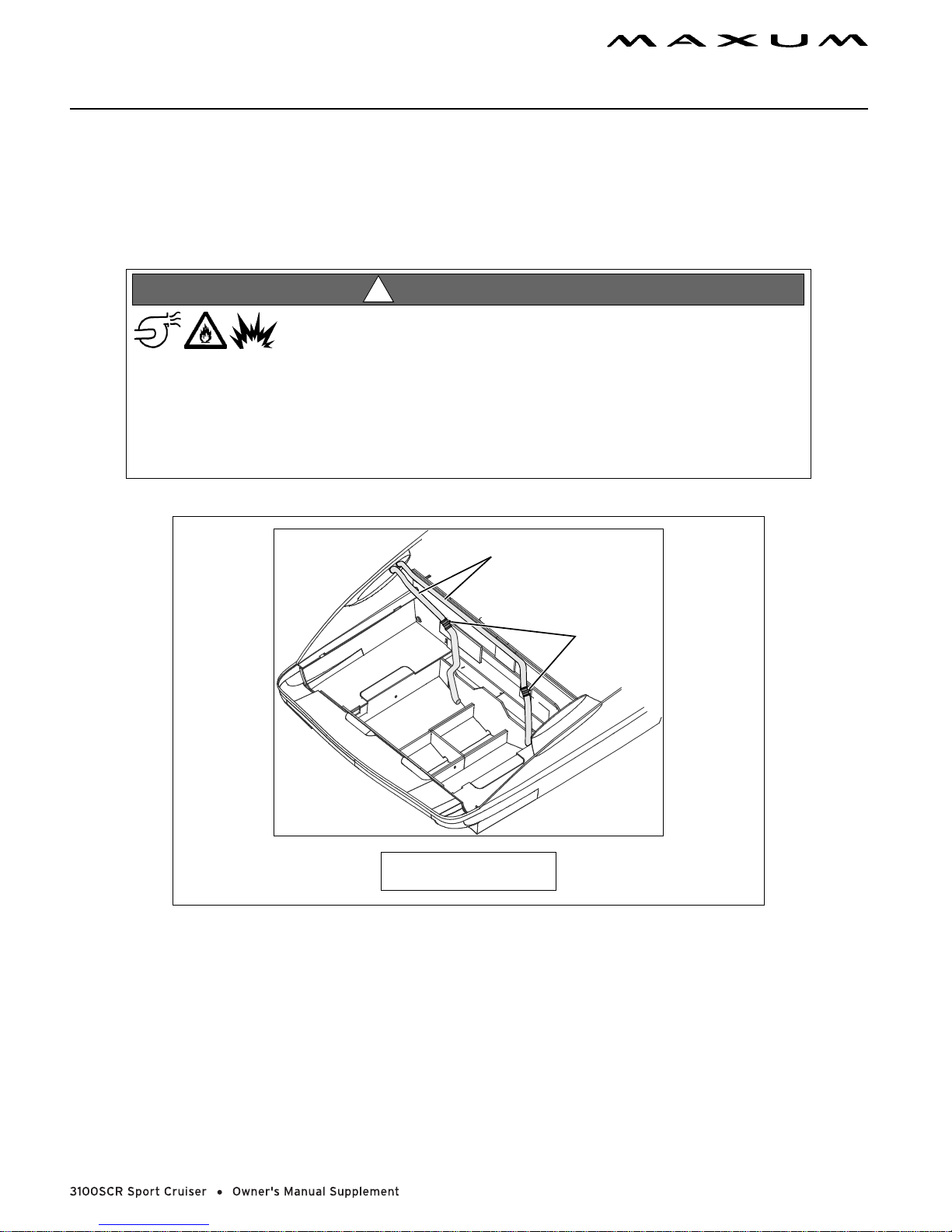
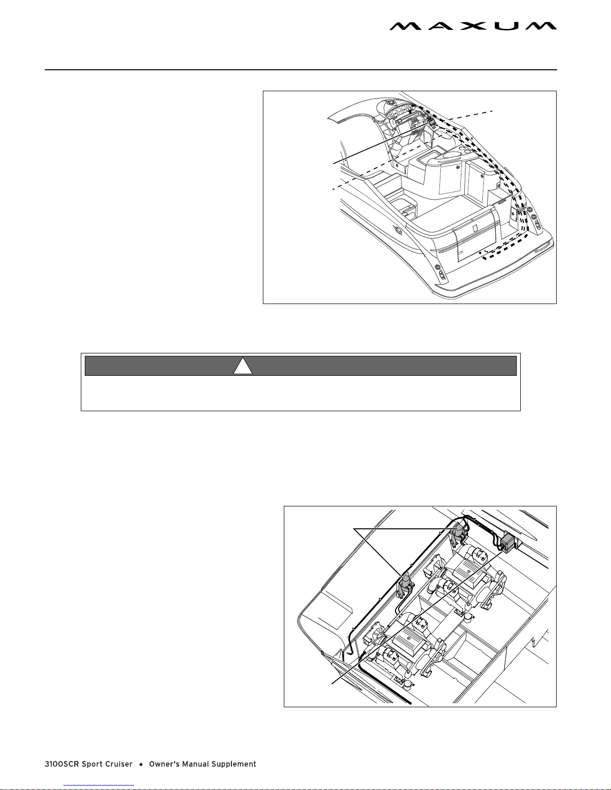
Engine Room Ventilation System
WARNING!
!
FIRE/EXPLOSION HAZARD
• Use of the blower system is NOT A GUARANTEE that explosive fumes have been removed .
• If you smell fuel, DO NOT start the engine or generator and DO NOT turn on any
electrical devices.
• If you smell fuel and the engines and/or generator is already running, SHUT OFF the
engines and/or generator and TURN OFF all elec tri cal devices. Investigate immediately.
• DO NOT obstruct or modify the venti lat ion system.
1
2
1 VENTILATION HOSES
2BLOWER MOTORS
• The bilge blower removes explosive fuel fumes from the engine compartment.
• Fresh air is drawn into the compartment through the deck vents.
• The bilge bl ower switch is at th e helm.
• If your boat is equipped with a generator, there is a second bilge blower switch on the main AC panel.
To make sure the engine compartment is ventilated with fresh air, run the bilge blower:
• For at least four minut es before starting the engines.
• During st arting.
• Anytime your boat is running below cruising speed.
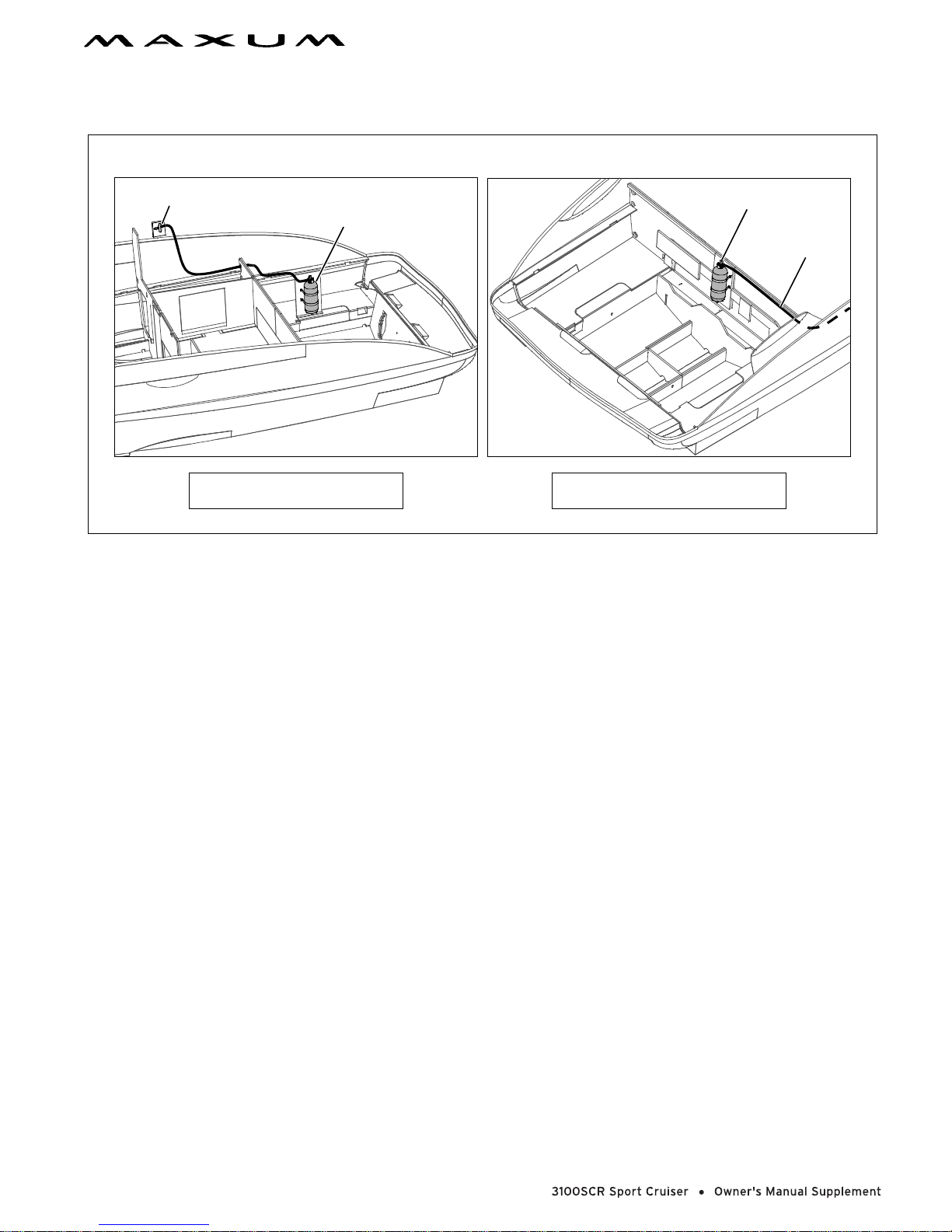
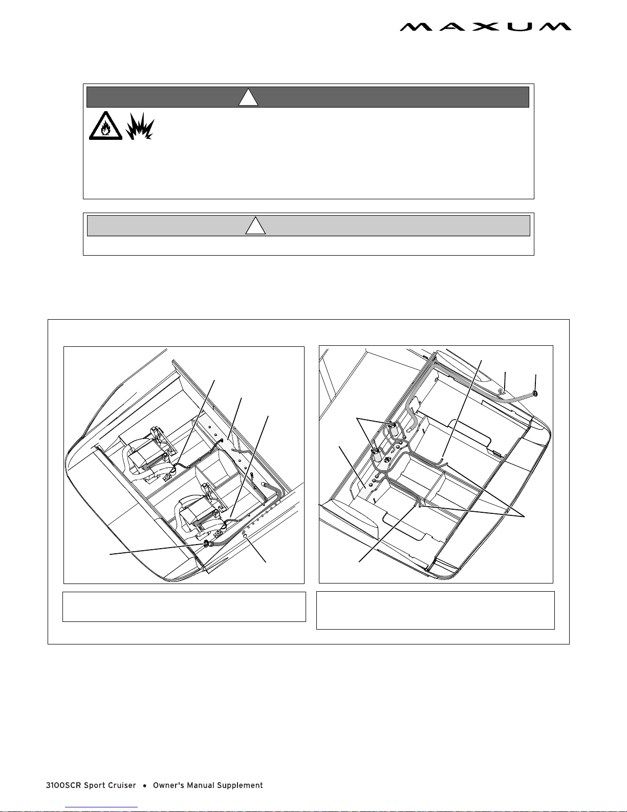
Fire Suppression System (If Equipped)
CHAPTER 3: PROPULSION & RELATED SYSTEMS 13
GAS SYSTEM
(IF EQUIPPED)
2
1 FIXED FIRE EXTINGUISHER
2 MANUAL DISCHARGE HANDLE
1
1 FIXED FIRE EXTINGUISHER
2 TO MANUAL DISCHARGE HANDLE
DIESEL SYSTEM
(IF EQUIPPED)
1
2
The fire suppression system is designed to extinguish a fire in the engine compartment.
Before using your boat for the first time, read and understand the fire suppression system’s instruction and mainte-
nance manual and follow all warnin gs.
Observe the fo llowing:
• The system will go off automatically whenever direct heat from a fire is detected in the engine compartment.
• The system can be set off manually by pulling the T-handle (labeled "FIRE") at the helm.
• The system can only be set of f once during a f ire. Afte r the sys tem is dis char ged it mus t be refi lled and refurbi shed
before it can be used again.
14 CHAPTER 3: PROPULSION & RELATED SYSTEMS
Fuel System
WA RNING!
!
FIRE/EXPLOSION HAZARD!
• It is very important that the fuel system be insp ected thoro ughly the first time it is fi lled and
at each subsequent filling.
• For your safety and the safety of your passengers , the f ueling instructions in the Cruiser &
Yacht Owner’s Manual must be carefully followed.
!
Avoid the storage or handling of gear near the fuel lines, fittings and tank.
Diagrams
CAUTION
GAS FUEL SYSTEM
(IF EQUIPPED)
4
1 FUEL LINE TO ENGINE
2FUEL TANK
1
2
1
3
3 FUEL TANK VENT
4 FUEL FILL
DIESEL FUEL SYSTEM
(IF EQUIPPED)
2
1
3
1 FUEL TANKS
2 FUEL FILTER
3 FUEL LINE TO ENGINE
3
4
6
4 FUEL TANK VENT
5 FUEL FILL
6 FUEL RETURN LINE
5
CHAPTER 3: PROPULSION & RELATED SYSTEMS 15
Fuel Fill and Vent
• The fuel fill fitting is marked “GAS” or “DIESEL”.
• The fuel tank vent is located below the fuel fill.
• If you experience difficulty filling the fuel tank, check to see that the fuel fill hose and vent hose are free of
obstructions and kinks.
Fuel Filters
• The fuel pickup tube (located inside the fuel tank) is equipped with a fine mesh screen filter.
• In addition, when supplied by the e ngine manufacturer, a fuel filter i s installed on the eng ines.
• Periodically replace the fue l fi lters to make sure they remain clean and fr e e of debris.
• Consult with your selling dealer or local marina concerning fuel additives that help to prevent fungus or other
buildup in your fuel tank.
Anti-siphon Valve
NOTICE
• If an engine running problem is diagnosed as fu el starvati on, check the anti-si phon valve. If
the valve is stuck or clogged, change or replace it while the engi nes are shut down.
• NEVER run the engines with the anti-siphon val ve r emo ved, exc ept i n an emer gency.
• Your boat is equipped with an anti-siphon valve, which is an integral part of fuel system.
• The valve is located at the point where the fuel feed line attaches to the fuel tank.
• The valve is spring loaded and is opened by fuel pump vacuum.
• This valve will prevent fuel from siphoning from the tank in the event of a fuel line rupture.
16
CHAPTER 4: CONTROLS
Steering
• This boat features a power assisted rack-andpinion steering system.
• Check the fluid level in the power steering
reservoir every time you use your boat.
• Boat steering is not self-centering.
SHIFT/THROTTLE
LEVER
STEERING
CABLE
SHIFT/THROTTLE
CABLE
Shift/Throttle
WARNING!
!
LOSS OF CONTROL HAZARD!
Improper maintenance of shift/throttle hardware may cause a sudden loss of contro l!
• Carefully read and understand the information about the shift/throttle in the Cruiser & Yacht Owner’s Manual.
• Also, read and understand the shifter/throttle and engine manuals included in your owner’s packet.
Power Trim and Tilt
• The stern drive on your boat is equipped with
power trim and tilt.
• Trim and tilt instructions are provided in the
engine operation manual and the shifter/throttle
manual, included in your owner’s packet.
TRIM/TILT
TRIM TAB
PUMP
PUMPS
 Loading...