

Maxum 1800MX, 1800SR3, 1900SR3, 2000SR3, 2100SC Owner's Manual
...

Engine Serial Number: _____________________________________________
Hull Identification Number:__________________________________________
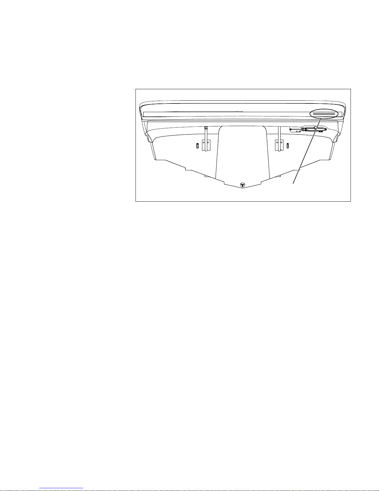
Hull Identification Number
• The Hull Identification Number
(HIN) is located on the starboa rd
side of the hull.
• Record the HIN (and the engine
serial numb er) in the spac e
provided above.
• Please refer to the HIN for any
correspondence or orders.
© 2004 Maxum Technical Publications. All rights reserved.
No part of this publication may be reproduced, stored in any retri eval system, or transmitted in any form by any means, electronic, mechanic al, photocopying,
recording or otherwise, without prior written permission of Maxum.
Printed in the United States of America.
General Notes
The material in this document is for information only and is subject to change wit hout notice. While reasonable efforts have been made in the preparation of this
document to assure its accuracy, Maxum assumes no liability resulting from errors or omission s in this document, or from the use of information contained herein.
Due to our commitment to produ ct improvement, Maxum reserves the right to make changes in the product design, specifications, and equipment at any time without notice or obligation. Illustra tions and/or photos may show optional equipment.
All Maxum products meet or exceed USCG (United States Coast Guard) and/or NMMA (National Marine Manufacturer’s Association) construction standards.
Manufactured with 1,1,1 Trichloroethane, a substance which harms public health and environment during the manufacturing process by destroying ozone in the
upper atmosphere.
Proprietary Rights
This document discloses subject matter in which Maxum has proprietary ri ghts. The information and design disclosed herein were originated by and are the property of Maxum. Neither receipt nor possession thereof confers or transfers any right to reproduce, copy, alter or disclose the document or any part thereof, any
information contained therein, or to construct boats or any item from it, exce pt by written permission from or written agreement with Maxum. This document is to
be returned upon request to Maxum.
HIN LOCATION

CONTENTS
1 Chapter 1: Welcome Aboard!
1 Dealer Service
1 Warranty Information
1 Boating Experience
2 Engine & Accessories Guidelines
2 Propeller
2 Engine & Accessories Literature
3 Structural Limitations
3 Qualified Maintenance
4 Safety Standards
4 Special Care For Moored Boats
5 Carbon Monoxide (CO)
5 Facts about CO
6 Where and How CO Can Accumulate
6 How to Protect Yourself and Others
From CO
7 CO Checklists
7 Carbon Monoxide Alarm System
(If Equipped)
8 More Information
9 Chapter 2: Product Specifications
9 1800MX
10 1800SR3
11 1900SR3
12 2000SR3
13 2100SC
14 2200SR3
15 Chapter 3: Locations
15 Exterior Views
15 Hull Views
16 1800MX Deck Views
17 1800SR3 Deck Views
18 1900SR3 Deck Views
19 2000SR3 Deck Views
20 2100SC Deck Views
21 2200SR3 Deck View
22 Helm Views
24 Component Locations
36 Chapter 4: Propulsion &
Related Systems
36 Engine
36 Special Starting Instructions for
Carbureted Engines (If Equipped)
37 Bilge Blower System
38 Fuel System
39 Fuel Fill & Vent
39 Anti-siphon Valve (Gas Engine Only)
40 Gas Engine Fuel Filters
40 Fuel Filter/Water Separator (Diesel
Engine Only)
41 Quick Oil Drain System
42 Fire Suppression System (If Equipped)
43 Chapter 5: Controls & Gauges
43 Steering
43 Rack-and-Pinion Steering System
43 Shift/Throttle Control
43 Power Trim and Tilt
44 Gauges
44 Cleaning Gauges
44 Gauge Fogging
44 Radio Transmission Interference
44 Depth Finder (If Equipped)
45 Chapter 6: Plumbing
45 Bilge Pump
46 Bilge Pump Testing
48 Freshwater System (2200SR Only)
49 Freshwater System Winterization
49 Transom Shower (2200SR Only)
50 Drain Systems
50 Deck Drains
50 Portable Toilet (2100SC Only) (If Equipped)
50 Portable Toilet Pump-Out (2100SC Only)
(If Equipped)

51 Chapter 7: Deck Equipment
51 Cleats and Tow Eyes
51 Ski Tow Ring
52 Ski-Tow Tower (If Equipped)
52 Attaching the Ski-Tow Rope
53 Folding The Ski-Tow Tower
54 Canvas
55 Bow Well Cover (Bowriders Only)
(If Equipped)
56 1800MX Convertible Top (If Equipped)
57 1800SR3, 1900SR3, & 2000SR3
Convertible Top (If Equipped)
58 2100SC & 2200SR3 Convertible Top
(If Equipped)
59 Side Curtains (If Equipped)
60 1800MX Bimini Top (If Equipped)
60 1800SR3 Bimini Top (If Equipped)
61 2100SC Bimini Top (If Equipped)
61 1900SR3, 2000SR3, & 2200SR3 Bimini
Top (If Equipped)
62 Canvas Care
63 Clear Vinyl Care
64 Chapter 8: Enter tainment Systems
64 Audio System
65 Chapter 9: Convertibl e Seats,
Beds, & Tables
65 Sleeper Seats (If Equipped)
65 Type ‘A’ Sleeper Seats (If Equipped)
66 Type ‘B’ Sleeper Seats (If Equipped)
67 Cuddy Cabin to V-Berth Conversion
(2100SC Only)
69 Jump Seat to Sunlounge Conversion
(If Equipped)
70 Engine Cover to Sunlounge Conversion
(If Equipped)
71 Chapter 10: Lights
71 Care and Maintenance
71 Interior & Exterior Lights
71 Navigation Lights
72 Chapter 11: Electrical System
73 12-Volt DC System
73 Battery
73 Battery Switch (If Equipped With
Two Batteries)
73 Battery Switch Positions
74 Fuses
74 12-Volt Accessory Outlet(s)
74 Alternator
75 Electrical Routings
75 1800MX Deck Electrical Harness
76 1800SR3, 1900SR3 and 2000SR3 Deck
Electrical Harness
77 2100SC Deck Electrical Harness
78 2200SR3 Deck Electrical Harness
79 Wiring Diagrams
79 1800MX
80 1800SR3, 1900SR3, & 2000SR3
81 2100SC
82 2200SR3
83 Important Records
84 Float Plan
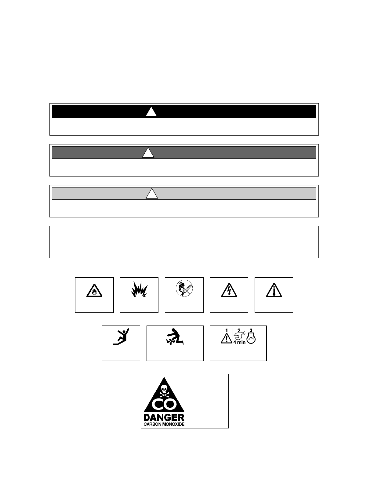
Hazard Boxes & Symbols
The hazard boxes and symbols shown below ar e used th rou ghout thi s Supplement to call attention to potentially dan-
gerous situations which could lead to either personal injury or product damage. Read ALL warnings carefully and
follow all safety instruction s.
This box alerts you to immediate hazard s which WILL cause severe per sonal injur y or death if
the warning is ignored.
DANGER!
!
This box alerts you to hazards or unsafe practices which COULD res u lt in severe personal
injury or death if the warning is ignored.
WARNING!
!
This box alerts you to hazards or unsafe practices which COULD res ult in minor personal
injury or cause product or property damage if the warning is ignored.
CAUTION
!
This box calls attention to installation, operation or maintenance information, which is important to proper operation but is not hazard r ela ted.
NOTICE
EXPLOSION
HAZARD!
NO OPEN
FLAME!
HOT
HAZARD!
ROTATING
PROPELLER HAZARD!
FALLING
HAZARD!
ELECTRICAL
HAZARD!
CO POISON ING
HAZARD!
FIRE
HAZARD!
RUN BILGE BLOWERS
FOR 4 MINUTES!

1
Chapter 1: Welcome Aboard!
• This Owner’s Manual Supplement provides information about your boat that is not covered in the Sport Boat
Owner’s Manual.
• Before using your boat, study this Owner’s Manual Supplement, the Sport Boat Owner’s Manual, and all engine
and accessory literature carefully.
• Keep this Owner’s Manual Supplement and the Sport Boat Owner’s Manual on your boat in a secure, yet readily
available place.
Dealer Service
• Your dealer is your key to service.
• Ask your dealer to explain all systems before taking delivery of your boat.
• Contact your dealer if you have any problems with your new boat.
• If your dealer cannot help, call our customer service hotline: 360-435-8957 or send us a FAX: 360-403-4235.
• Buy replacement parts from any authorized Maxum dealer.
Warranty Information
• Maxum offers a Limited Warranty on each new Maxum purchased through an authorized Maxum dealer.
• A copy of the Limited Warranty was included in your owner’s packet.
• If you did not rec eive a copy of the Limited Warranty, please contact your Maxum dealer or c all 360- 435-895 7 for
a copy.
Boating Experience
If this is your first boat or if you are changing to a type of boat you are not familiar with, for your own comfort and
safety, obtain handling and operating experience before assuming command of this boat.
Take one of the boating safety classes offered by the U.S. Power Squadrons or the U.S. Coast Guard Auxiliary.
For more course information, including dates and locations of upcoming classes, contact the organizations directly:
• U.S. Power Squadrons: 1-888-FOR-USPS (1-888-367-8777) or on the Internet at: http://www.usps.org
• In Canada, for the CPS courses call 1-888-CPS-BOAT.
• U.S. Coast Guard Auxiliary: 1-800-368-5647 or on the Internet at: http://www.cgaux.org
Outside the United States, your selling dealer, national sailing federation or local boat club can advise you of local
sea school s or competen t instructors.
CONTROL HAZARD!
A qualified operator must be in control of the boat at all times. Do NOT operate your boat
while under the influence of alcohol or dr ugs.
WARNI NG!
!
Chapter 1: Welcome Aboard!
2
Engine & Accessories Guidelines
• Your boat’s engine and accessories were selected to provide optimum performance and service.
• Installing a different engine or other accessories may cause unwanted handling characteristics.
• Should you choose to install a different engine or to add accessories that will affect the boat’s running trim, have
an experienced marine technician perform a safety inspection and handling test before operating your boat again.
Certain modifications to your boat will result in cancellation of your warranty protection.
• Always check with your dealer before making any modifications to your boat.
Propeller
• Keep the propeller in good repair and at the correct pitch for your particular situation.
• A slightly bent or nicked propeller will adversely affect the performance of your boat.
Engine & Accessories Literature
• The engine and accessories installed on your boat come with their own operation and maintenance manuals.
• Read thes e manuals before using the engine and accessories.
• Unless noted otherwise, all engine and a ccessory lite rature referred to in this Supplement is included in your
owner’s packet.
When storing your boat please r ef er t o your e ngine’s operation and maintenance manuals.
NOTICE
ENGINE DAMAGE HAZARD!
The factory standard propell er may not be the best for your particular boat and load
conditions. Refer to the engine manual for engine RPM ratings. The engine should reach,
but NOT exceed its ful l rated RPM whe n full -t hrottle is applied.
Immediately contact your local Maxum dealer if:
• The engine cannot reach its full ra ted RPM when ful l-throttle is applied, or;
• The engine exceeds its full rated RPM when full-t hrottle is applied.
CAUTION
!

Chapter 1: Welcome Aboard!
3
Structural Limitations
The extended swim platform is designed to be lightweight for proper boat balance. The load limit for the extended
swim step is 30 pounds per square foot, evenly distributed.
Qualified Maintenance
• Failure to maintain your boat’s systems (listed in the warning above) as designed could violate the laws in your
jurisdiction and could expose you and other people to the danger of bodily injury or accidental death.
• Follow the instruction s provided in the Sport Boat Owner’s Manual, this Supplement, the engine owner’s manual
and all accessory literature.
To maintain the integrity and safety of your boat, allow only quali fi ed per sonnel to pe rform
maintenance on, or in any way modify the:
• Steering System
• Propulsion System
• Engine Control System
• Fuel System
• Environmental Control Syst em
• Electrical System
• Navigational System
WARNI NG!
!

Chapter 1: Welcome Aboard!
4
Safety Standards
• Your boat’s mechanical and electrical systems were designed to meet safety standards in effect at the time it
was built.
• Some of these standard s were mandat ed by law, all of them were designed to in sure your safety, and the safety of
other people, vessels and property.
In addition to this Supplement, please read the Sport Boat Owner’s Manual and all accessory instructions for impor-
tant safety standards and hazard information.
Special Care For Moored Boats
• Whether moored in saltwater or freshwater, your boat will collect marine growth on its hull bottom.
• This will detract from the boat’s beauty, greatly affect its performance and may damage the gelcoat.
• Periodically haul the boat out of the water and scrub the hull bottom with a bristle brush and a solution of soap
and water.
FA LLING an d ROTA TING PROPE LLER HAZ ARD!
• NEVER allow anyone to ride on parts of the boat NOT designed for
such use.
• Sitting on seat backs, lounging on the forward deck, bow r iding ,
gunwale riding or occupying the transom platf orm whil e under way is e spec ial ly haz ardous
and will cause personal injury or death.
DANGER!
!
ROTATING PROPELLER and CARBON MONOXIDE
POISONING HAZARD!
• NEVER allow anyone to occupy , or ha ng from, the
back deck or swim platform while the engine(s)
are running.
• Teak surfing, dragging, or water skiing within 20 f eet
of a moving watercraft can be fatal.
DANGER!
!
DANGER
PERSONAL SAF ETY HAZARD!
ALWAYS secure the anc hor and ot her l oose objects before getting underway. The anchor and
other items that are NOT pr ope rly secured can come loose when the boat is moving and cause
personal injury or death.
DANGER!
!
• T o help s eal the hul l bottom and reduc e the possi bility of gelcoat bl istering on moored bo ats,
apply an epoxy barrier coating.
• The barrier coating should be cover ed wi th se veral coat s of anti -f ouli ng paint.
• Many states regulate the chemical co ntent of bottom paints in order to meet env ironmental
standards. Check with your local deale r about recommended bottom paints, and about the
laws in effect in your area.
NOTICE
Chapter 1: Welcome Aboard!
5
Carbon Monoxide (CO)
Facts about CO
• CO poisoning causes a significant number of boating deaths each year.
• Called the "silent killer", CO is an extremely toxic, colorless, odorless and tasteless gas.
• CO can harm or even kill you inside or outside your boat.
• CO can affect you whether you’re underway, moored, or anchored.
• CO symptoms are similar to seasickness or alcohol intoxication.
• CO can make you sick in seconds. In high enough concentrations, even a few breaths can be fatal.
• Breathing CO blocks the ability of your blood to carry oxygen.
• The effects are cumulative, even low levels of exposure can result in injury or death.
Factors That Increase the Effects of CO Poisoning
• Age
• Smokers or people exposed to high concentrations of cigarette smoke
• Consumption of alcohol
• Lung disorders
• Heart problems
• Pregnancy
• Carbon monoxide gas (CO) is colorless, odorless, tas tel ess , and
extremely danger ous .
• All engines, generators, and fuel burning applianc es produce CO
as exhaust.
• Prolonged exposure to lo w concent rat ions or ver y quic k exposu r e to hi gh
concentrations will cause BRAIN DAMAGE or DEATH.
• Teak surfing, dragging, or water skiing within 20 feet of a moving water-
craft can be fatal.
DANGER!
!

Chapter 1: Welcome Aboard!
6
Where and How CO Can Accumulate
Stati onary Conditions That Increase CO Accumulations Include:
To correct stationary situations A and/or B:
• Close all windows, portlights and hatches.
• If possible, move your boat away from source of CO.
Running Conditions That Increase CO Accumulations Include:
To correct running situations C and/or D:
• Trim bow down.
• Open windows and canvas.
• When possible, run boat so that prevailing winds help dissipate exhaust.
How to Protect Yourself and O thers From CO
• Know where and how CO may accumulate in and around your boat (see above).
• Maintain fresh air circulation throughout the boat at all times.
• Know where your engine and generator exhaust outlets are located and keep everyone away from these areas.
• Never sit on, or hang onto, the back deck or swim platform while the engine(s) are running.
• Never enter the areas under swim platforms where exhaust outlets are located.
• Although CO can be present without the smell of exhaust fumes, if exhaust fumes are detected on the boat, take
immediate action to dissipate these fumes.
• Treat sympt oms of se asick ness as possib le CO pois oning. Get the pe rson into f resh a ir immediately. Seek medical
attention—unless you’re sure it’s not CO.
• Install and maintain CO monitors inside your boat. Do not ignore any alarm. Replace monitors as recommended
by the monitor manufacturer.
• Follow the checklists provided on the next page.
• Get a Vessel Safety Check.
For information on how to get a free VESSEL SAFETY CHECK, visit www.vesselsafetycheck.org or contact your
local U.S. Coast Guard Auxiliary or United States Power Squadrons®.
• U.S. Coast Guard Auxiliary: 1-800-368-5647 or on the Internet at: http://www.cgaux.org
• U.S. Power Squadrons: 1-888-FOR-USPS (1-888-367-8777) or on the Internet at: http://www.usps.org
A. Using engine, generator, or other fuel burn-
ing device when boat is moored in a confined space.
B. Mooring too close to another boat that is
using its engine, generator, or other fuel
burning device.
C. Running boat with trim angle of bow too high. D. Running boat without through ventilation
(station wagon effect).

Chapter 1: Welcome Aboard!
7
CO Checklists
Trip Checklist
❏ Make sure you know where the exhaust outlets are located on your boat.
❏ Educate all passengers about the symptoms of CO poisoning and where CO may accumulate.
❏ When docked, or rafted with another boat, be aware of exhaust emissions from the other boat.
❏ Listen for any change in exhaust sound, which could indicate an exhaust component failure.
❏ Test the operation of each CO alarm by pressing the test button.
Monthly Checklist
❏ Make sure all exhaust clamps are in place and secure.
❏ Look for exhaust leaking from exhaust system components. Signs include rust and/or black streaking, water
leaks, or corroded or cracked fittings.
❏ I nspect rubbe r exh aust h ose s for burne d, cra cked, o r det eriorat ed secti ons. All ru bber hoses shoul d be pliable and
free of kinks.
Annual Checklist
Have a Qualified Marine Technician:
❏ Replace exhaust hoses if cracking, charring, or deterioration is found.
❏ Ensure that your engines and generators are properly tuned, and well maintained.
❏ Inspect each water pump impeller and the water pump housing. Replace if worn. Make sure cooling systems are
in working condition.
❏ Inspect all metallic exhaust components for cracking, rusting, leaking, or loosening. Make sure they check the
cylinder head gasket, exhaust manifold, water injection elbow, and the threaded adapter nipple between the manifold and the elbow.
❏ Clean, inspect, and confirm proper operation of the generator cooling water anti-siphon valve (if equipped).
Carbon Monoxide Alarm System (If Equipped)
• Do not disconnect the CO monitor.
• Read the manufacturer’s instructions for your CO monitor. If you did not receive the manufacturer’s instruc-
tions, call (800) 383-0269 and one will be mailed to you.
If your boat is not equipped with a CO monitor, consider purchasing one from your dealer or marine supply store.
The stereo memory and CO monitor place a small , but constant drain on the battery.
NOTICE

Chapter 1: Welcome Aboard!
8
More Information
For more informati on about h ow you can p revent ca rbon monoxid e pois oning on r ecreati onal boat s and oth er ways t o
boat more sa fely, contact:
For information on how to get a free VESSEL SAFETY CHECK, visit www.vesselsafetycheck.org or contact your
local U.S. Coast Guard Auxiliary or United States Power Squadrons®.
• U.S. Coast Guard Auxiliary: 1-800-368-5647 or on the Internet at: http://www.cgaux.org
• U.S. Power Squadrons: 1-888-FOR-USPS (1-888-367-8777) or on the Internet at: http://www.usps.org
U
nited States Coast Guard
O
ffice of Boating Safety (G-OPB-3)
2
100 Second Street SW
W
ashington, DC 20593
w
ww.uscgboating.org
1
-800-368-5647
National Marine Manufacturers
Association (NMMA)
200 East Randolph Drive
Suite 5100
Chicago, IL 60601-9301
www.nmma.org
312-946-6200
American Boat & Yacht Council, In
c.
(ABYC)
3069 Solomon’s Island Road
Edgewater, MD 21037- 1416
www.abycinc.org
410-956-1050
9
Chapter 2: Product Specifications
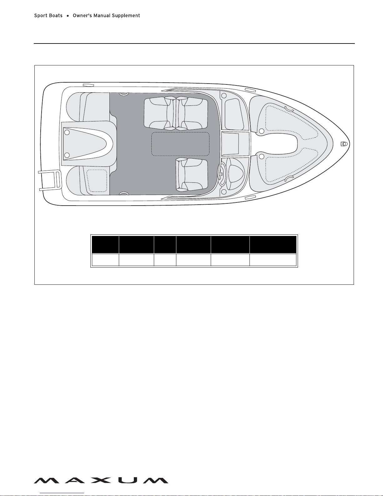
1800MX
Overall
Length
Bridge
Clearance
Beam
Draft
(Drive Up)
Draft (Drive
Down)
Fuel Capacity
17' 7" 5' 8" 7' 0" 1' 6" 2' 11" 21 Gallons
STANDARD SEATING LAYOUT
Chapter 2: Product Specifications
10
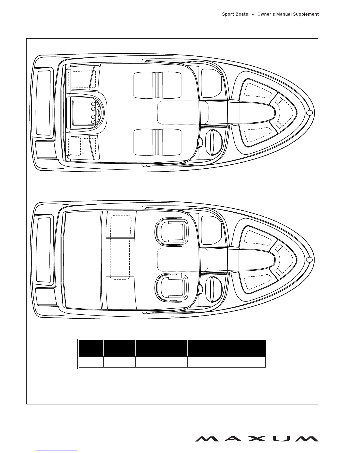
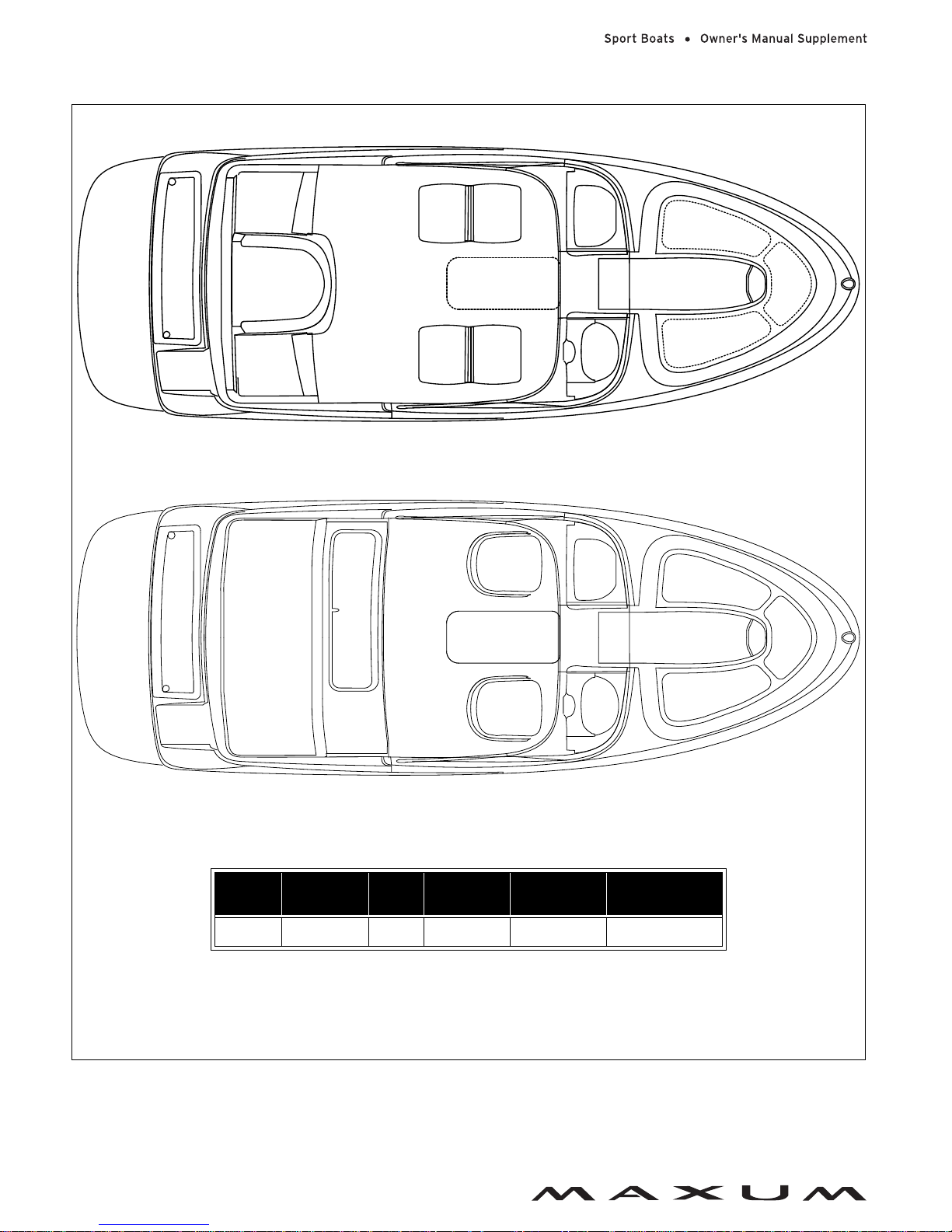
1800SR3
Overall
Length
Bridge
Clearance
Beam
Draft
(Drive Up)
Draft (Drive
Down)
Fuel Capacity
18' 0" 6' 7" 7' 7" 1' 9" 3' 1" 28 Gallons
STANDARD SEATING LAYOUT
SPORT SEATING LAYOUT
NOTE: HELM BUCKET SEAT/PASSENGER SLEEPER SEAT LAYOUT NOT SHOWN
Chapter 2: Product Specifications
11
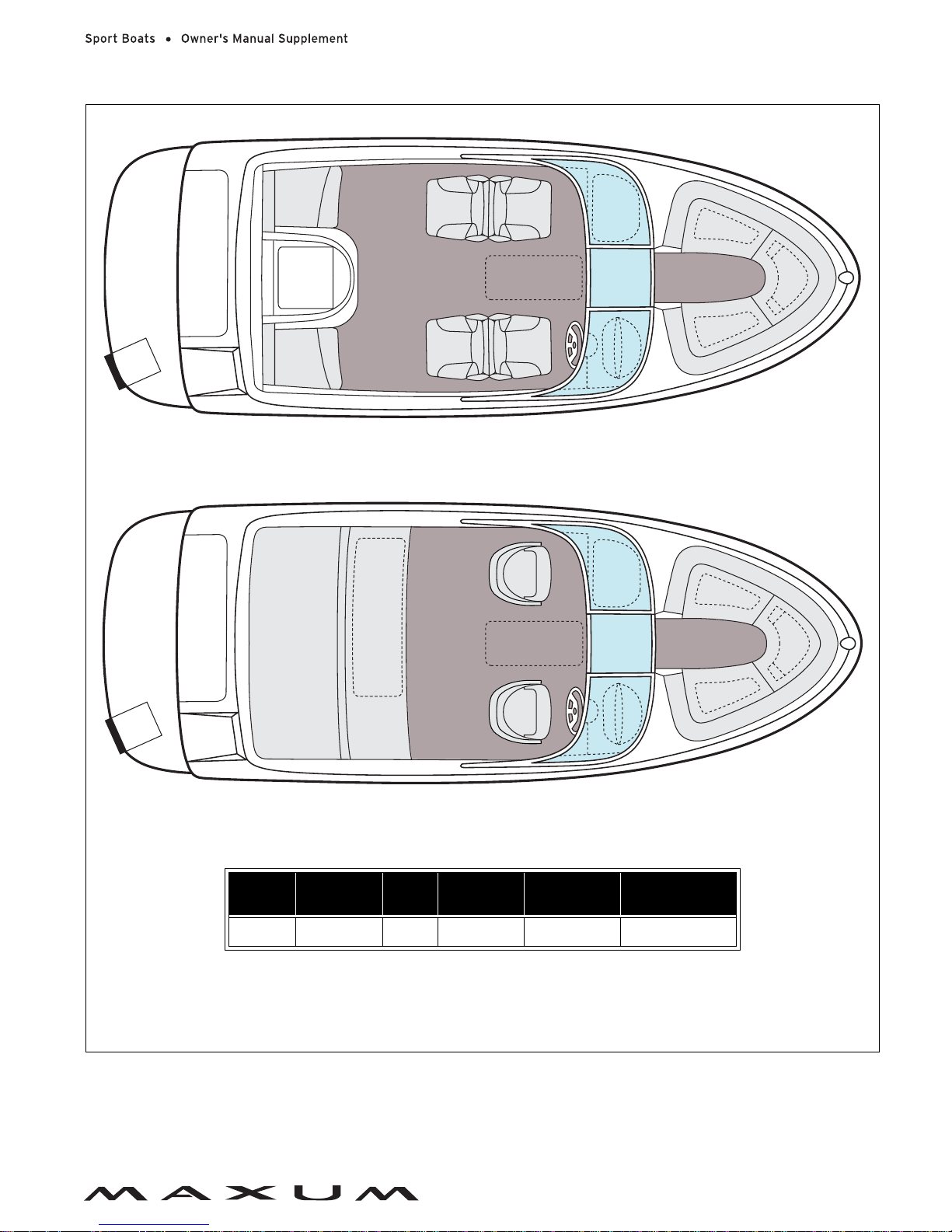
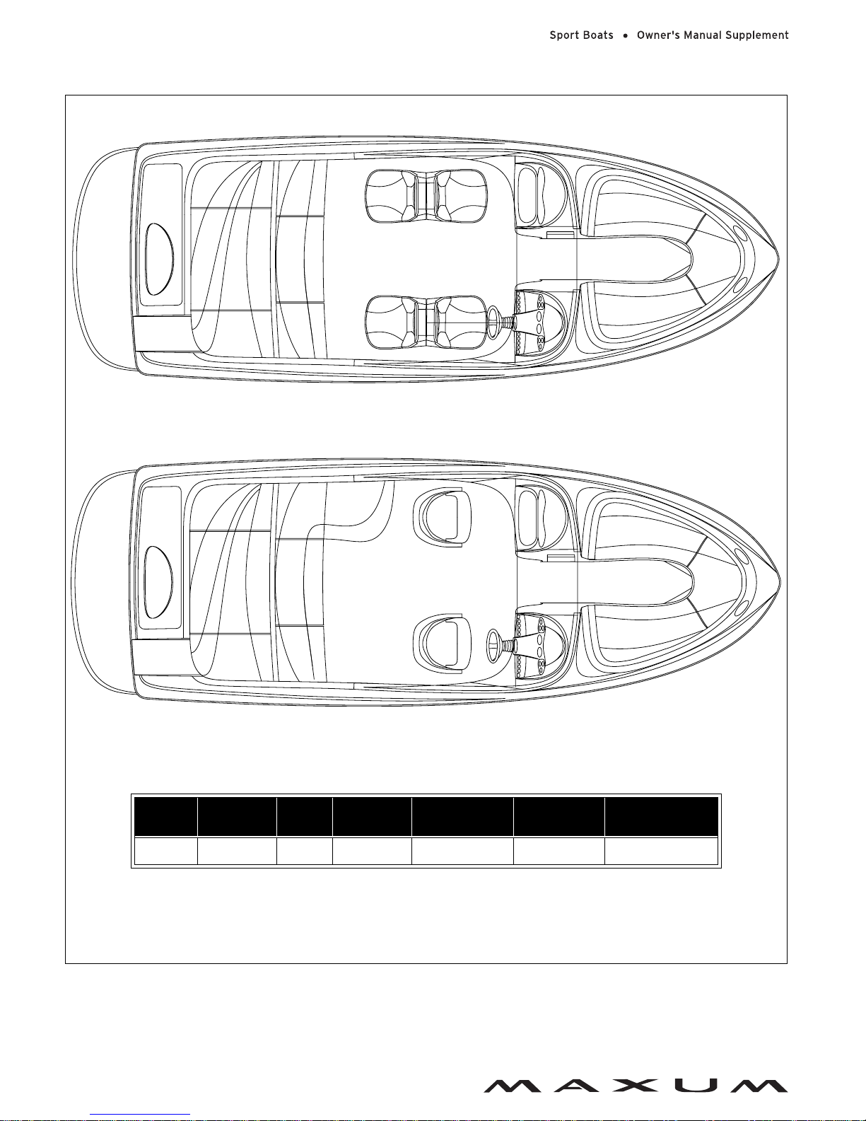
1900SR3
Overall
Length
Bridge
Clearance
Beam
Draft
(Drive Up)
Draft (Drive
Down)
Fuel Capacity
19' 0" 7' 0" 7' 11" 1' 9" 3' 3" 35 Gallons
STANDARD SEATING LAYOUT
SPORT SEATING LAYOUT
NOTE: HELM BUCKET SEAT/PASSENGER SLEEPER SEAT LAYOUT NOT SHOWN
Chapter 2: Product Specifications
12
2000SR3
Overall
Length
Bridge
Clearance
Beam
Draft
(Drive Up)
Draft (Drive
Down)
Fuel Capacity
20' 4" 6' 7" 8' 0" 1' 8" 3' 1" 35 Gallons
STANDARD SEATING LAYOUT
SPORT SEATING LAYOUT
NOTE: HELM BUCKET SEAT/PASSENGER SLEEPER SEAT LAYOUT NOT SHOWN
Chapter 2: Product Specifications
13
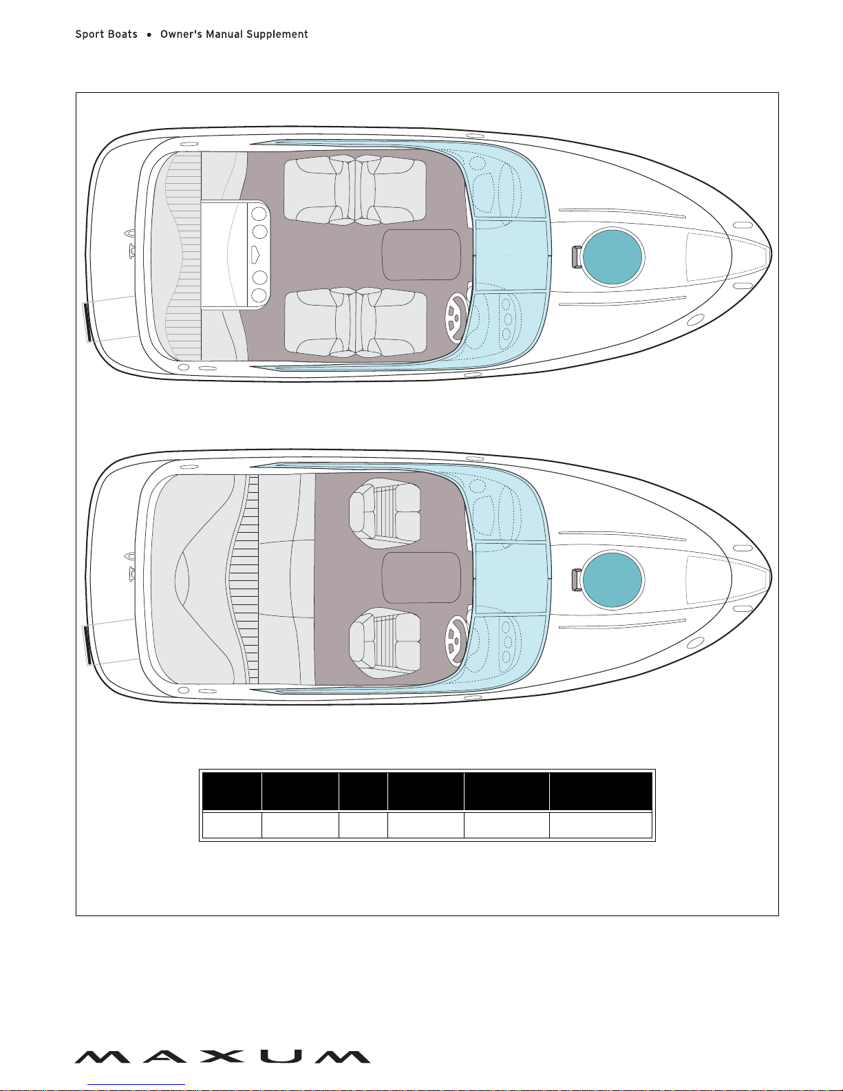
2100SC
Overall
Length
Bridge
Clearance
Beam
Draft
(Drive Up)
Draft (Drive
Down)
Fuel Capacity
21' 6" 4' 10" 8' 6" 1' 5" 2' 9" 50 Gallons
STANDARD SEATING LAYOUT
SPORT SEATING LAYOUT
NOTE: HELM BUCKET SEAT/PASSENGER SLEEPER SEAT LAYOUT NOT SHOWN
Chapter 2: Product Specifications
14
2200SR3
NOTE: HELM BUCKET SEAT/PASSENGER SLEEPER SEAT LAYOUT NOT SHOWN
STANDARD SEATING LAYOUT
SPORT SEATING LAYOUT
Overall
Length
Bridge
Clearance
Beam
Draft
(Drive Up)
Draft
(Drive Down)
Fuel
Capacity
Freshwater
Capacity
22' 1" 7' 0" 8' 6" 1' 8" 3' 2" 50 Gallons 10 Gallons
15
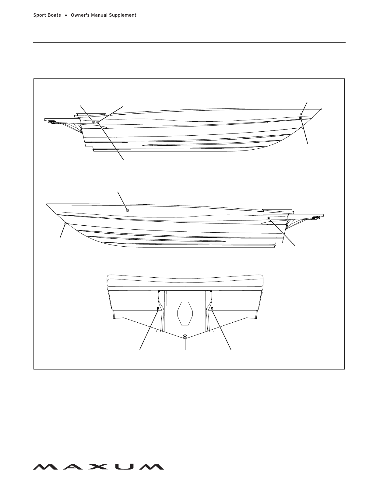
Chapter 3: Locations
Exterior Views
Hull Views
GARBOARD
DRAIN PLUG
STERN EYESTERN EYE
STARBOARD HULLSIDE
TRANSOM
BOW EYE
BILGE PUMP
DRAIN
PORT HULLSIDE
DASH DRAIN
STORAGE
COMPARTMENT
DRAIN (1800SR3,
ANCHOR LOCKER DRAIN
(2100SC ONLY)
PORTABLE HEAD
PUMP-OUT VENT
(2100SC ONLY)
(IF EQUIPPED)
1900SR3, 2000SR3,
& 2200SR3 ONLY)
DECK DRAIN
(1800SR3, 1900SR3,
& 2000SR3 ONLY)
TRANSOM STORAGE
COMPARTMENT DRAIN
Chapter 3: Locations
16
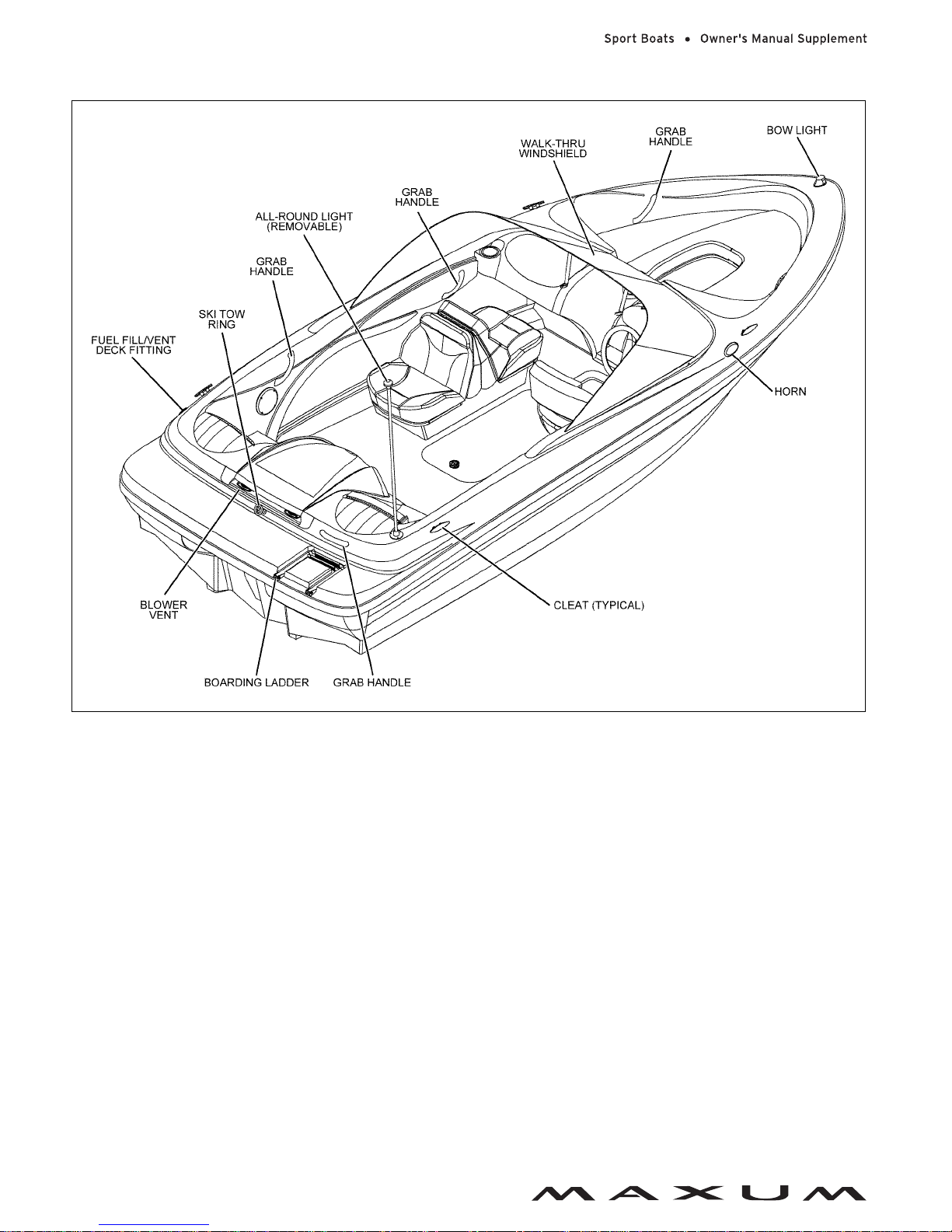
1800MX Deck Views
Chapter 3: Locations
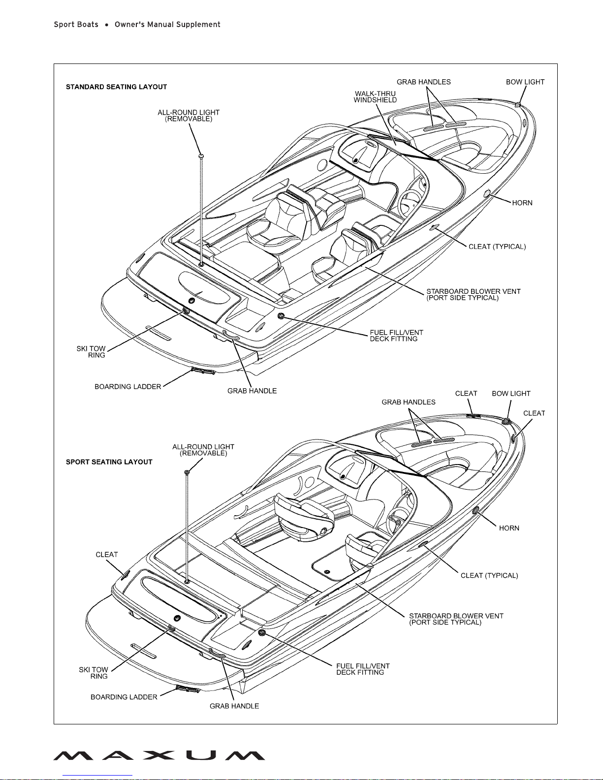
17
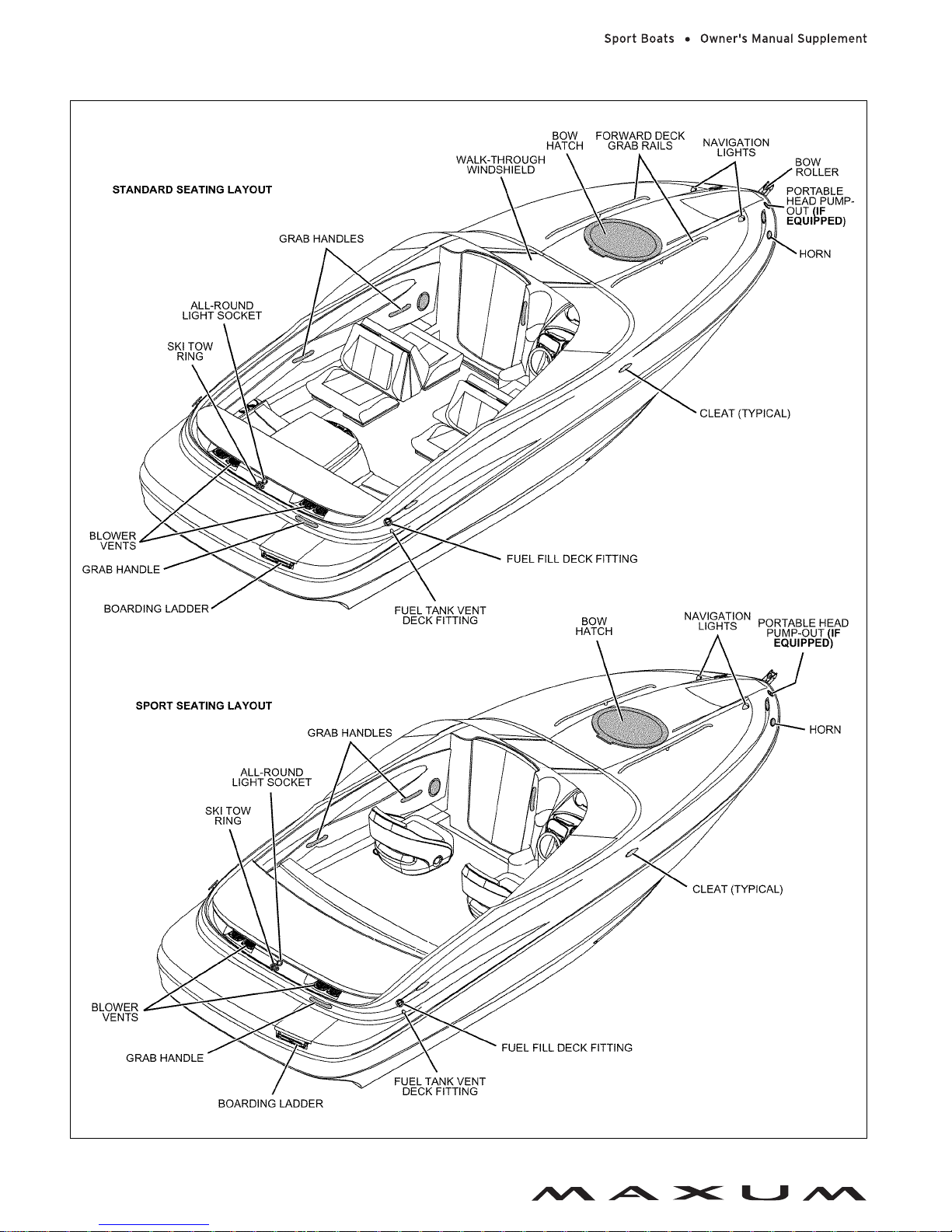
1800SR3 Deck Views
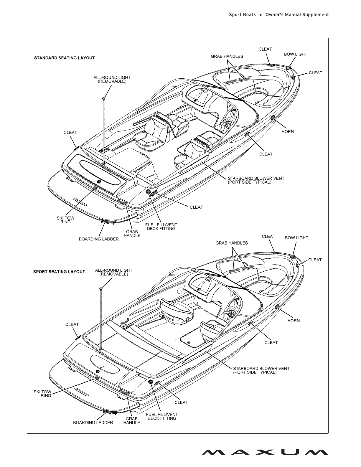
Chapter 3: Locations
18
1900SR3 Deck Views
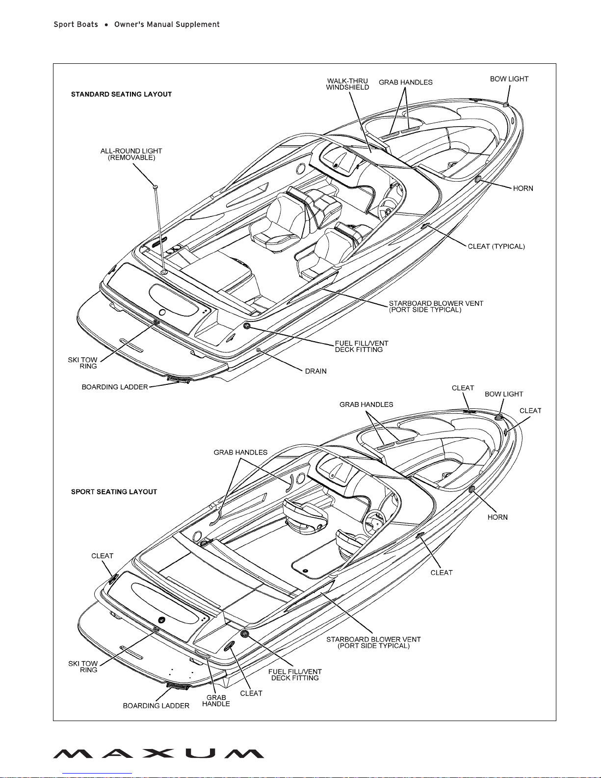
Chapter 3: Locations
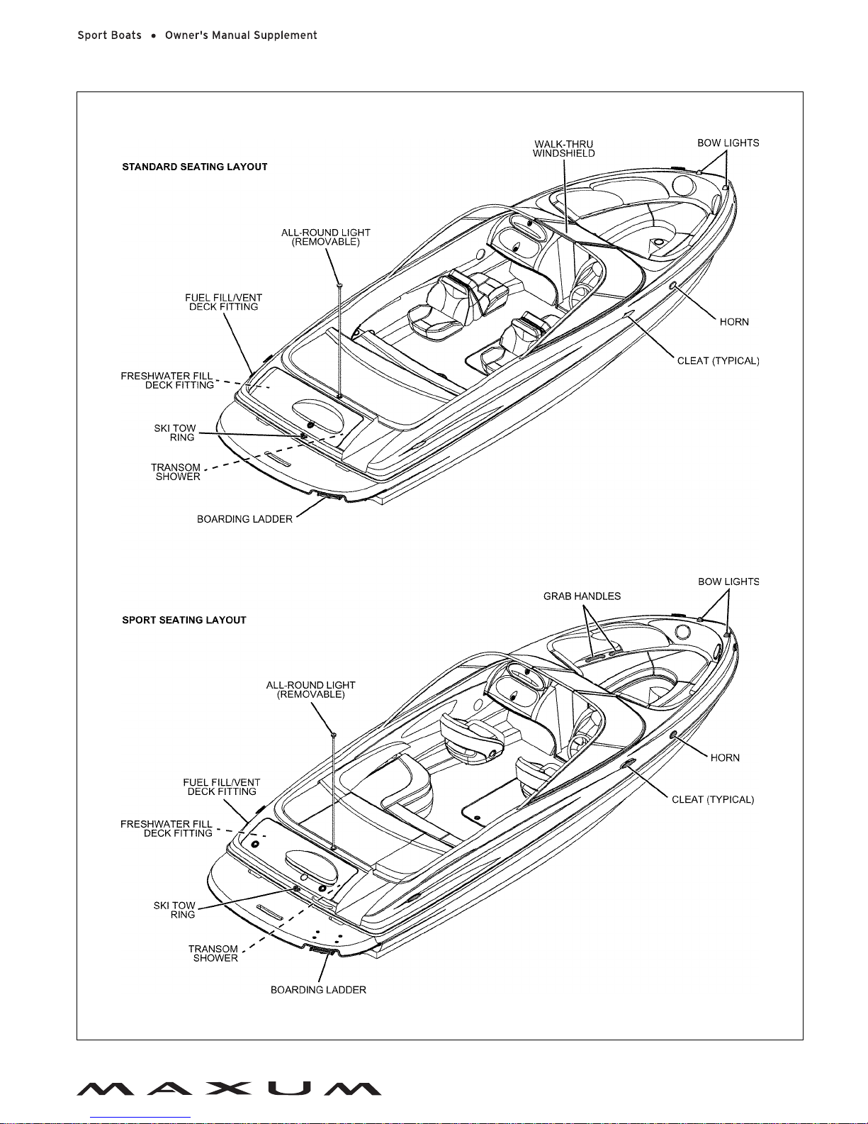
19
2000SR3 Deck Views
Chapter 3: Locations
20
2100SC Deck Views
Chapter 3: Locations
21
2200SR3 Deck View
Chapter 3: Locations
22
Helm Views
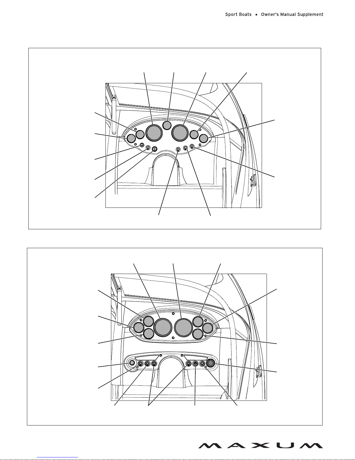
1800MX
1800SR3, 1900SR3, & 2000SR3
ACTUAL LAYOUT MAY VARY DEPENDING
ON ENGINE AND ACCESSORY OPTIONS
NOTE: TYPICAL HELM LAYOUT SHOWN
SPEEDOMETER
TRIM
GAUGE
TACHOMETER
OIL PRESSURE
GAUGE
FUEL GAUGE
BILGE PUMP
SWITCH
ACCESSORY
SWITCH
VOLTMETER
HORN SWITCH
BLOWER SWITCH
IGNITION SWITCH
TEMPERATURE GAUGE
NAVIGATION/ANCHOR
LIGHTS 3-WAY SWITCH
SPEEDOMETERTACHOMETER OIL PRESSURE GAUGE
FUEL GAUGE
TRIM GAUGE
12-VOLT OUTLET
HORN
SWITCH
NAVIGATION/ANCHOR
LIGHTS 3-WAY SWITCH
ACCESSORY
SWITCHES
BLOWER SWITCH
IGNITION SWITCH
BILGE PUMP
SWITCH
DEPTH SOUNDER
(IF EQUIPPED)
VOLTMETER
TEMPERATURE
GAUGE
TRIM GAUGE
ACTUAL LAYOUT MAY VARY DEPENDING
ON ENGINE AND ACCESSORY OPTIONS
NOTE: TYPICAL HELM LAYOUT SHOWN
Chapter 3: Locations
23
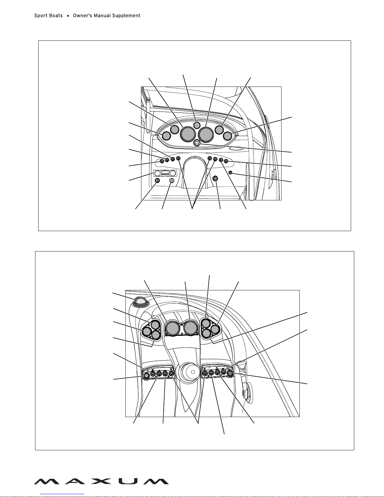
2100SC
2200SR3
OIL PRESSURE
GAUGE
TEMPERATURE
GAUGE
SPEEDOMETER
TRIM GAUGE
TACHOMETER
DEPTH SOUNDER
(IF EQUIPPED)
HORN SWITCH
VOLTMETER
FUEL GAUGE
IGNITION
SWITCH
BLOWER
SWTICH
12-VOLT
OUTLET
STEREO
COURTESY LIGHT
SWITCH
ACTUAL LAYOUT MAY VARY DEPENDING
ON ENGINE AND ACCESSORY OPTIONS
NOTE: TYPICAL HELM LAYOUT SHOWN
BILGE PUMP
SWITCH
ACCESSORY
SWITCHES
ACCESSO R Y SW ITCH
NAVIGATION
LIGHT SWITCH
ANCHOR LIGHT
SWITCH
VOLTMETER
TEMPERATURE
GAUGE
SPEEDOMETER
COMPASS
TACHOMETER
OIL PRESSURE
GAUGE
TRIM GAUG E
12-VOLT OUTLET
HORN SWITCH
WATER PUMP
SWITCH
COURTESY LIGHT
SWITCH
NAVIGATION/ANCHOR
LIGHTS 3-WAY SWITCH
ACCESSORY
SWITCHES
BILGE PUMP
SWITCH
BLOWER
SWITCH
IGNITION SWITCH
DEPTH SOUNDER
(IF EQUIPPED)
FUEL GAUGE
ACTUAL LAYOUT MAY VARY DEPENDING
ON ENGINE AND ACCESSORY OPTIONS
NOTE: TYPICAL HELM LAYOUT SHOWN
 Loading...