

Maxtronic Co INDY-2400 Users Manual

Chapter 2 : " Getting Started "
General Overview
This chapter helps you get ready to use the Disk Array. It gives you :
Unpacking & Checklist
Choosing a place for Disk Array
Identifying Parts of Disk Array
Power Source
Installing the Hard Disk Drives
Host Linkage
Power-On and Self-test
LED Display and Function Keys
LCD Status Display
The following illustrations will help you read the further sections.
Special Note :
RAID should never be considered a replacement for doing
regular backup. It's highly recommended to conduct a
backup strategy for critical data.
2-1
Getting Started
Unpacking & Checklist
Before unpacking your Disk Array , prepare a clean and stable
place to put the contents of your Disk Array's shipping container on.
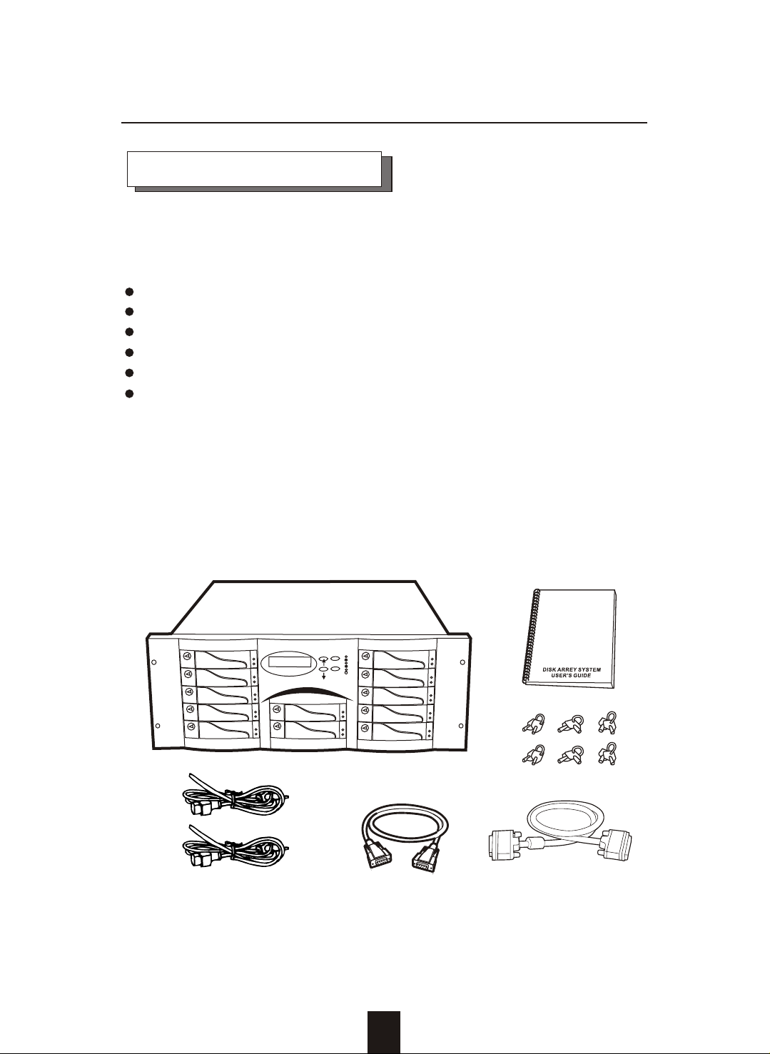
Altogether, you should find the following items in the package :
The Disk Array
AC power cord
One External SCSI cable
Keys ( For HDD Trays )
User Guide
RS-232 Cable
Remove all the items from the carton. If anything is missing or
broken , please inform your dealer immediately.
Save the cartons and packing materials that came with the Disk
Array. Use these materials for shipping or transporting the Disk Array.
Figure : Checklist
E
S
C
E
n
t
er
2-2

Getting Started
Choosing a place for Disk Array
When selecting a place to set up your Disk Array, be sure to follow
the guidelines as below:
Place on a flat and stable surface.
Use a stand that supports at least 50 kgs for this Disk Array.
(HDD included )
Place the Disk Array close enough to the computer for the Disk
Array's External SCSI cable to reach it.
Use a grounded wall outlet.
Avoid an electrical outlet controlled by wall switches or
automatic timers. Accidental disruption of the power source
may wipe out data in the memory of your computer or Disk
Array.
Keep the entire system away from potential sources of
electromagnetic interference, such as loudspeakers , cordless
telephones, etc.
Caution !
Avoid direct sunlight, excessive heat, moisture, or dust.
2-3

Identifying Parts of the Disk Array
Front View
Getting Started
2 4
8
9
1
5
3
6
E
S
C
E
nte
r
7
Figure : Front View
1. LCD Status Display Panel
2. HDD Trays 1 ~ 5 (From Up to Down)
3. HDD Trays 6 & 7
4. HDD Trays 8 ~12
5. Function Keys ( , , Enter , ESC )
6. Power-On Indicator ( PWR Unit 1 , PWR Unit 2 )
7. Host Computer Access Indicator
8. HDD Tray Lock ( Lock / Unlock )
9. HDD Status Indicator
( Error (Red), Access (Yellow), Power-On (Green))
2-4
REAR VIEW
Getting Started
12
1
2 4
5 73
6
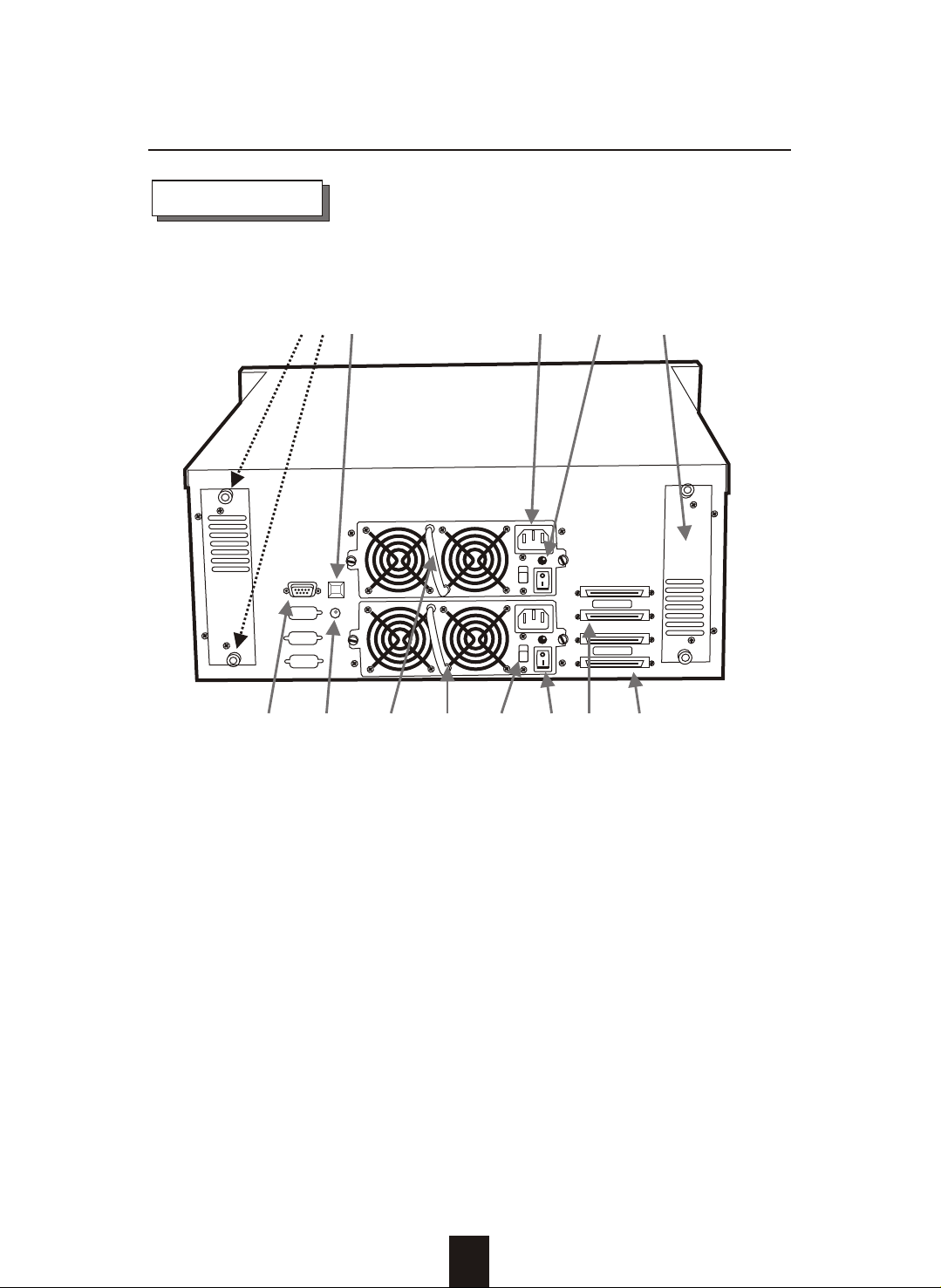
Figure : Rear View
1. RS-232 Adapter (Terminal Port)
2. Power Supply Fail Indicator (Red)
3. Power Supply Unit On / Off Switch (0 / I)
4. Power Supply Unit 1
5. Power Supply Unit 2
6. AC Voltage Select Switch (115V/230V)
7. SCSI Channel Port ------( Host 1 )
8. SCSI Channel Port ------( Host 2 )
9. Cooling Fan
10. Power Supply "Power-On" Indicator (Green)
11. AC Power Input Socket
12. Power Supply "Alarm" Reset Button
13. Cooling Fan Screws
9101113
Host Port 1
Host Port 2
8
2-5
 Loading...