

MaxTronic SS-4503E, SS-4503R User Manual

SS-4503E & SS-4503R
Hardware Manual
iSCSI to SAS
Disk Array Systems
Version 1.0

SS-4503E & SS-4503R
iSCSI to SAS
Disk Array Systems
Hardware User Manual


Table of Contents
Copyright ..................................................................................................................................................................... i
CE Statement .............................................................................................................................................................. i
C-Tick .......................................................................................................................................................................... i
FCC Statement ............................................................................................................................................................ i
CB Statement .............................................................................................................................................................. i
Symbols used in this manual ....................................................................................................................................... i
Important Safety Instructions, Care and Handling ....................................................................................................... ii
Chapter 1: Product Overview.......................................................................................................... 1
Package Contents ............................................................................................................................................................... 1
System Requirements ......................................................................................................................................................... 2
Panel View .......................................................................................................................................................................... 3
Disk Tray ............................................................................................................................................................................. 4
SS-4503E (Single Controller) Rear View ........................................................................................................................... 5
SS-4503R (Redundant Controller) Rear View .................................................................................................................... 6
Chapter 2: Hardware Installation .................................................................................................... 7
Installing the Hard Disks...................................................................................................................................................... 7
SAS hard disks ............................................................................................................................................................ 7
SATA hard disks .......................................................................................................................................................... 9
Combining SATA-SAS................................................................................................................................................. 11
Mounting the RAID system.................................................................................................................................................. 13
Chapter 3: System Connections..................................................................................................... 13
Connecting to the Host........................................................................................................................................................ 13
Connecting the GUI Management Port ............................................................................................................................... 13
Connecting the CLI Management Port ................................................................................................................................ 14
Connecting JBOD Enclosure............................................................................................................................................... 14
Connecting and Turning On the Power ............................................................................................................................... 15
Chapter 4: Maintenance .................................................................................................................. 16
Replacing a Disk ................................................................................................................................................................. 16
Replacing a Controller......................................................................................................................................................... 17
Replacing a Power Supply .................................................................................................................................................. 18
Upgrading Memory .............................................................................................................................................................. 19
Replacing a Fan Module ..................................................................................................................................................... 20
Installing Battery Backup Module ........................................................................................................................................ 21
Appendix A: Specifications ............................................................................................................ 23
Technical Specifications .............................................................................................................................................. 23
Controller Specifications.............................................................................................................................................. 23
Appendix B: Accessories................................................................................................................ 24
Preface
Copyright
Copyright © 2010 by MaxTronic. All rights reserved. No part of this publication may be reproduced or transmitted in any
form without prior written permission of MaxTronic.
CE Statement
This device is in conformity with the EMC.
C-Tick
The product complies with the Australian EMC standard "Limits and methods of measurement of radio
disturbance characteristics of information technology equipment, AS/NZS 3548:1995 Class B."
FCC Statement
This equipment has been tested and found to comply with the limits for a Class A digital device,
pursuant to Part 15 of the FCC Rules. These limits are designed to provide reasonable protection
against harmful interference when the equipment is operated in a commercial environment. This
equipment generates, uses, and can radiate radio frequency engery and, if not installed and used in
accordance with the instruction manual, may cause harmful interference to radio communications. Operation of this
equipment in a residential area is likely to cause harmful interference in which case the user will be required to correct the
interference at his own expense.
CB Statement
This device meets the requirements of the CB standard for electrical equipment with regard to establishing a satisfactory
level of safety for persons using the device and for the area surrounding the equipment. This standard covers only safety
aspects of the above equipment; it does not cover other matters, such as style or performance.
Symbols used in this manual
This manual highlights important information with the following icons:
Caution
This icon indicates the existence of a potential hazard that could result in personal injury, damage
to your equipment or loss of data if the safety instruction is not observed.
Note
This icon indicates useful tips on getting the most from your RAID system.
i
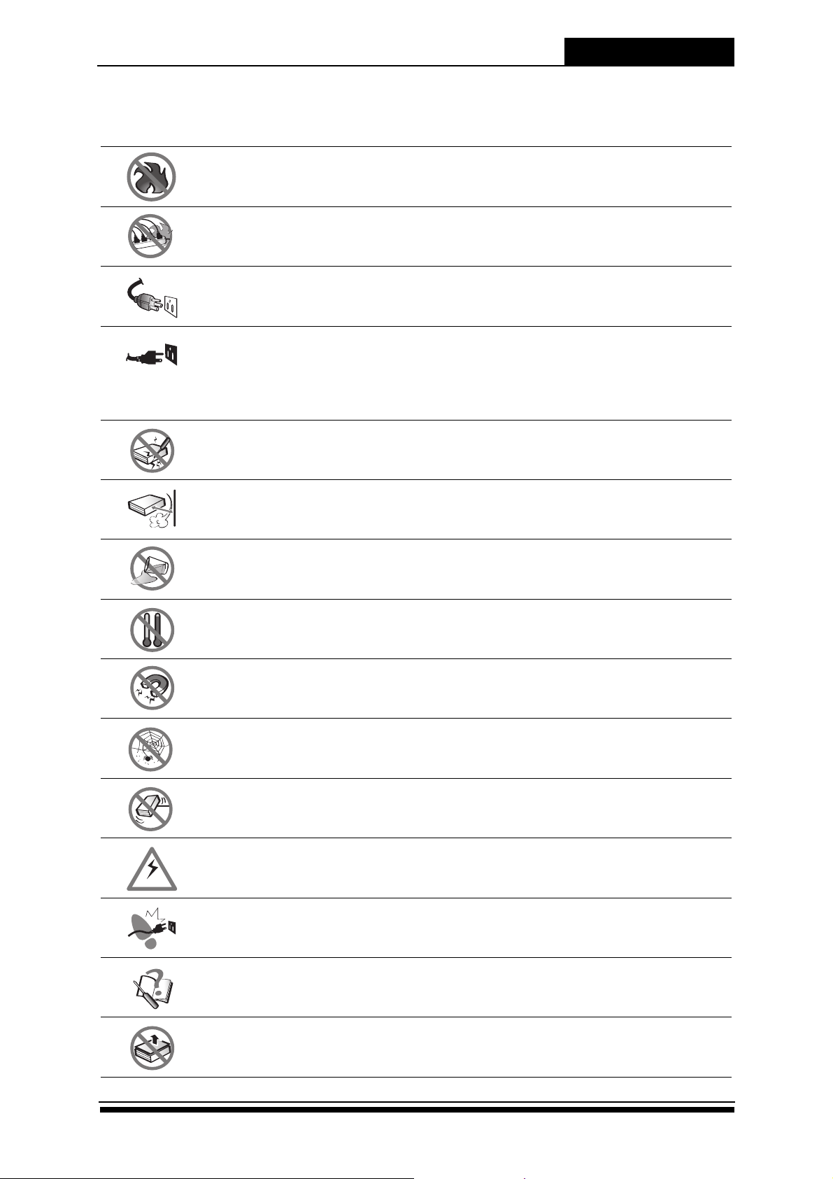
Important Safety Instructions, Care and Handling
L
H
v
Before starting with the RAID installation, read this user manual carefully and save it for later reference.
Do not place the RAID system near a radiator or other heat source.
If an extension cord or power center is used with the RAID system, make sure that the total current
consumption plugged into the wall outlet does not exceed the ampere rating.
This power cord will only fit into a grounded type of power outlet.
Unplug the power cord from the wall outlet before cleaning or servicing.
Unplug the power cord from the wall outlet and refer to qualified service personnel under the following
conditions:
If the RAID system has been exposed to water or any liquid.
If the RAID system has been dropped or the casing damaged.
Never push any kind of object through the slots and openings.
Preface
Slots and opening are for ventilation. Never block or cover them. Never place the RAID system on a bed,
sofa, rug or other similar surfaces.
Do not place the RAID system near water or any liquid.
Protect the RAID system from extremely high or low temperatures.
Keep the RAID system away from magnetic objects.
Keep the RAID system away from dust, sand, or dirt.
Place the RAID system on a stable area. Protect the RAID system from being dropped or mishandled,
any of this may cause damage to the product.
Ensure that the RAID system voltage corresponds to the supply voltage.
Do not place the RAID system where the power cord may be stepped on.
Do not attempt to service the RAID system yourself. Opening or removing the cover may expose you to
dangerous voltage or other risks.
Do not remove the cover.
ii
Product Overview
Hardwa
rd User Manual
Chapter 1: Product Overview
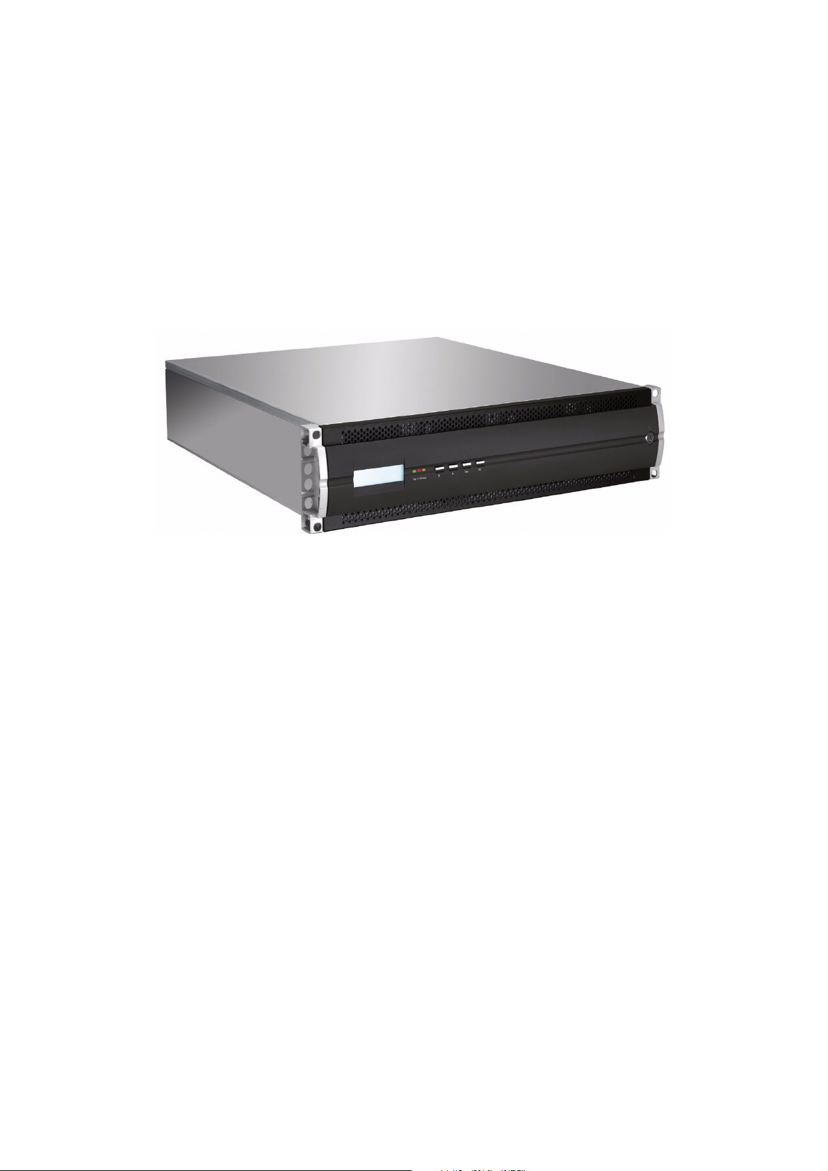
Congratulations on your purchase of this SS-4503E/SS-4503R RAID system. Aiming at serving versatile applications, the
SS-4503E/SS-4503R RAID system ensures not only data reliability but also improves system availability. Supported with
cutting-edge IO processing technologies, the RAID system delivers outstanding performance and helps to build
dependable systems for heavy-duty computing, workgroup file sharing, service-oriented enterprise applications, online
transaction processing, uncompressed video editing, or digital content provisioning. With its advanced storage
management capabilities, the RAID system is an excellent choice for both on-line and near-line storage applications. The
following sections in this chapter will present an overview of the features of SS-4503E/SS-4503R RAID system.
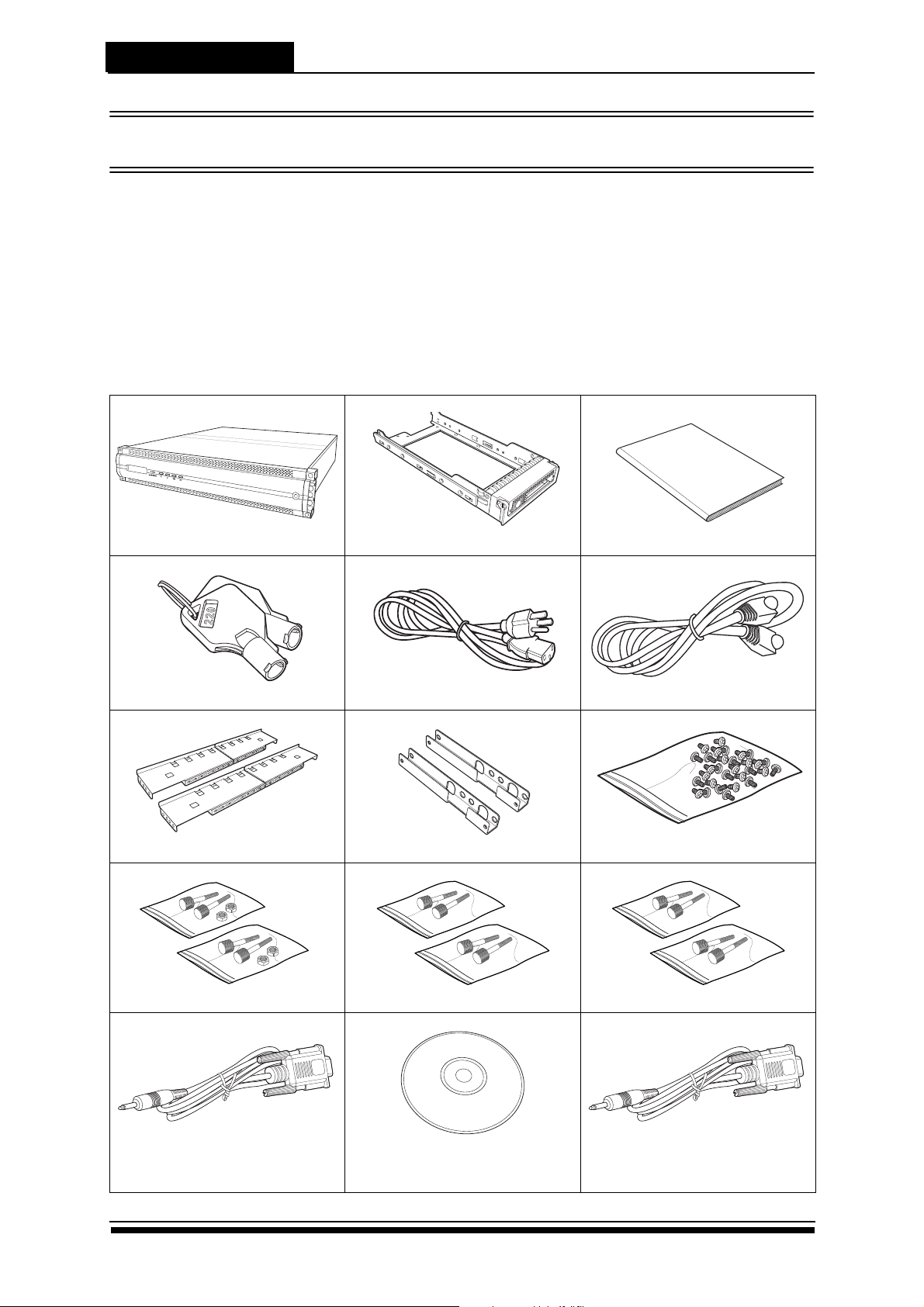
1.1 Package Contents
The following items come with your RAID system package, if any of them is missing or damaged, please contact your
supplier.
RAID system
Front panel key x 2
Rail x 1 set
Hard disk tray x 12
Power cable x 2
Rail extender x 1 set
Quick Install Guide
RJ-45 Lan cable
Screw pack
M5 fix screw x 2 packs
Terminal cable
Phonejack to DB-9(male)
(SS-4503E x1; SS-4503R x2)
1
M6 fix screw x 2 packs UNC # 10-32 fix screw x 2 packs
CD-ROM
UPS cable x 1
Phonejack to DB-9(Female)

Product Overview
Caution
The RAID system is heavey, be careful when lifting or moving it.
1.2 System Requirements
Operating Environment
• Ambient temperature of 5º C to 40º C
• Ambient non-operating temperature of -25º C to 60º C
• Non-condesing relative humidity of 20% to 80%
• Dust, smoke, and oil free environment
• No direct sunlight
• Flat and stable surface capable of supporting the RAID system
LAN management port settings
SS-4503E/SS-4503R support DHCP (Dynamic Host Configuration Protocol) to establish an IP address. To know current
IP address by simultaneously pressing ENT + EXT button on the front panel twice.
Ethernet settings can be set using the LCD or CLI (Command Line Interface). Please refer to the software manual for
more information.
2
Product Overview
Enter ESC
Power P/S Fail Access
1
2 3 4
9
5 6 7 8
Disk1
Disk2
Disk3
Disk4
Disk5
Disk6
Disk7
Disk8
Disk9
Disk10
Disk11
Disk12
Disk Mapping
Color Status
Bule Access
Green Disk Online
Red No Disk
Tray LED Indication
1132 3 4 5 6 7 8 9 10 11 12
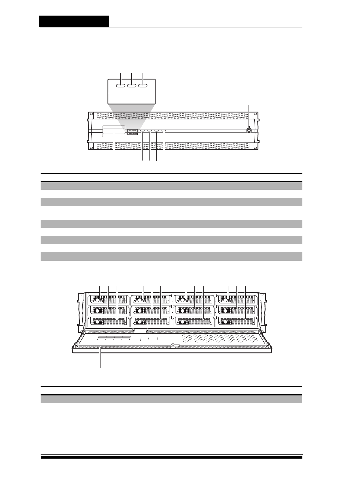
1.3 Panel View
Closed Front Panel
No. Item Description
1 LCD panel Displays RAID system information.
2 Power LED Indicates RAID system is powered on.
3 Power supply failed indicator Indicates a failed power supply.
4 Host computer access indicator Indicates data activity is in progress between the RAID system
5 Up button Use to move up the LCD menu.
6 Down button Use to move down the LCD menu.
7 Enter button Use to confirm or select an item.
8 Escape button Use to return to the previous LCD menu.
9 Lock Locks the front cover.
and the host computer.
Open Front Panel
No. Item Description
1-12 Disk trays 1-12 Hot-swappable disk trays. Holds the disk drives.
13 Front panel door Protects the disk drives.
3
 Loading...