

Page 1

DiamondMax 2
0
B
A
6
0
40 - 300G
AT
November 200
PN: 10043521
Page 2

© 2006, Maxtor Corporation All rights reserved
Publication number: 100435210, Rev. A
November 2006
Maxtor and MaxFax are registered trademarks of Maxtor Corporation, registered in the
U.S.A. and other countr ies. Maxtor DiamondMax, AutoTransfer, AutoRead, AutoWrite, DisCache, DiskWare, Defect Free Interface, QuickView, and WriteCache are trademarks of
Maxtor Corporation . All o ther b rand nam es or trade marks a re the propert y of the ir ma nufac turers.
Maxtor reserves the rig ht to change, without notice, product offerings or specifications. No
part of this publica tion may be r eproduced in any form witho ut written p ermission of Maxtor
Corporation.
Page 3

DiamondMax 20 PATA Product Manual, Rev. A i
Page 4

ii DiamondMax 20 PATA Product Manual, Rev. A
Page 5

Contents
1.0 Introduction. . . . . . . . . . . . . . . . . . . . . . . . . . . . . . . . . . . . . . . . . . . . . . . . . . . . . . . . . . . . . . . . . . . 1
2.0 Drive specifications . . . . . . . . . . . . . . . . . . . . . . . . . . . . . . . . . . . . . . . . . . . . . . . . . . . . . . . . . . . . 3
2.1 Specification summary tables . . . . . . . . . . . . . . . . . . . . . . . . . . . . . . . . . . . . . . . . . . . . . . . 3
2.2 Formatted capacity . . . . . . . . . . . . . . . . . . . . . . . . . . . . . . . . . . . . . . . . . . . . . . . . . . . . . . 12
2.2.1 LBA mode . . . . . . . . . . . . . . . . . . . . . . . . . . . . . . . . . . . . . . . . . . . . . . . . . . . . . 12
2.3 Default logical geometry . . . . . . . . . . . . . . . . . . . . . . . . . . . . . . . . . . . . . . . . . . . . . . . . . . 12
2.4 Recording and interface technology . . . . . . . . . . . . . . . . . . . . . . . . . . . . . . . . . . . . . . . . . 13
2.5 Physical characteristics . . . . . . . . . . . . . . . . . . . . . . . . . . . . . . . . . . . . . . . . . . . . . . . . . . . 13
2.6 Seek time. . . . . . . . . . . . . . . . . . . . . . . . . . . . . . . . . . . . . . . . . . . . . . . . . . . . . . . . . . . . . . 13
2.7 Start/stop times . . . . . . . . . . . . . . . . . . . . . . . . . . . . . . . . . . . . . . . . . . . . . . . . . . . . . . . . . 14
2.8 Power specifications . . . . . . . . . . . . . . . . . . . . . . . . . . . . . . . . . . . . . . . . . . . . . . . . . . . . . 15
2.8.1 Power consumption . . . . . . . . . . . . . . . . . . . . . . . . . . . . . . . . . . . . . . . . . . . . . . 15
2.8.2 Conducted noise . . . . . . . . . . . . . . . . . . . . . . . . . . . . . . . . . . . . . . . . . . . . . . . . 18
2.8.3 Voltage tolerance . . . . . . . . . . . . . . . . . . . . . . . . . . . . . . . . . . . . . . . . . . . . . . . . 18
2.8.4 Power-management modes. . . . . . . . . . . . . . . . . . . . . . . . . . . . . . . . . . . . . . . . 18
2.9 Environmental specifications. . . . . . . . . . . . . . . . . . . . . . . . . . . . . . . . . . . . . . . . . . . . . . . 19
2.9.1 Ambient temperature . . . . . . . . . . . . . . . . . . . . . . . . . . . . . . . . . . . . . . . . . . . . . 19
2.9.2 Temperature gradient. . . . . . . . . . . . . . . . . . . . . . . . . . . . . . . . . . . . . . . . . . . . . 19
2.9.3 Humidity. . . . . . . . . . . . . . . . . . . . . . . . . . . . . . . . . . . . . . . . . . . . . . . . . . . . . . . 19
2.9.4 Altitude. . . . . . . . . . . . . . . . . . . . . . . . . . . . . . . . . . . . . . . . . . . . . . . . . . . . . . . . 19
2.9.5 Shock. . . . . . . . . . . . . . . . . . . . . . . . . . . . . . . . . . . . . . . . . . . . . . . . . . . . . . . . . 20
2.9.6 Vibration. . . . . . . . . . . . . . . . . . . . . . . . . . . . . . . . . . . . . . . . . . . . . . . . . . . . . . . 20
2.10 Acoustics . . . . . . . . . . . . . . . . . . . . . . . . . . . . . . . . . . . . . . . . . . . . . . . . . . . . . . . . . . . . . . 21
2.11 Electromagnetic immunity . . . . . . . . . . . . . . . . . . . . . . . . . . . . . . . . . . . . . . . . . . . . . . . . . 22
2.12 Reliability . . . . . . . . . . . . . . . . . . . . . . . . . . . . . . . . . . . . . . . . . . . . . . . . . . . . . . . . . . . . . . 23
2.12.1 Annualized Failure Rate (AFR and Mean Time Between Failures (MTBF) . . . . 23
2.13 Agency certification . . . . . . . . . . . . . . . . . . . . . . . . . . . . . . . . . . . . . . . . . . . . . . . . . . . . . . 23
2.13.1 Safety certification . . . . . . . . . . . . . . . . . . . . . . . . . . . . . . . . . . . . . . . . . . . . . . . 23
2.13.2 Electromagnetic compatibility. . . . . . . . . . . . . . . . . . . . . . . . . . . . . . . . . . . . . . . 23
2.13.3 FCC verification . . . . . . . . . . . . . . . . . . . . . . . . . . . . . . . . . . . . . . . . . . . . . . . . . 24
2.14 Environmental protection. . . . . . . . . . . . . . . . . . . . . . . . . . . . . . . . . . . . . . . . . . . . . . . . . . 25
2.14.1 European Union Restriction of Hazardous Substances (RoHS) . . . . . . . . . . . . 25
2.15 Corrosive environment . . . . . . . . . . . . . . . . . . . . . . . . . . . . . . . . . . . . . . . . . . . . . . . . . . . 25
3.0 Configuring and mounting the drive . . . . . . . . . . . . . . . . . . . . . . . . . . . . . . . . . . . . . . . . . . . . . 27
3.1 Handling and static discharge precautions . . . . . . . . . . . . . . . . . . . . . . . . . . . . . . . . . . . . 27
3.2 Breather filter hole precautions . . . . . . . . . . . . . . . . . . . . . . . . . . . . . . . . . . . . . . . . . . . . . 28
3.3 Jumper settings . . . . . . . . . . . . . . . . . . . . . . . . . . . . . . . . . . . . . . . . . . . . . . . . . . . . . . . . . 29
3.3.1 Master/slave configuration. . . . . . . . . . . . . . . . . . . . . . . . . . . . . . . . . . . . . . . . . 29
3.3.2 Cable select option. . . . . . . . . . . . . . . . . . . . . . . . . . . . . . . . . . . . . . . . . . . . . . . 29
3.3.3 Ultra ATA/100 cable. . . . . . . . . . . . . . . . . . . . . . . . . . . . . . . . . . . . . . . . . . . . . . 30
3.4 Drive mounting . . . . . . . . . . . . . . . . . . . . . . . . . . . . . . . . . . . . . . . . . . . . . . . . . . . . . . . . . 30
4.0 ATA interface . . . . . . . . . . . . . . . . . . . . . . . . . . . . . . . . . . . . . . . . . . . . . . . . . . . . . . . . . . . . . . . . 33
4.1 ATA interface signals and connector pins . . . . . . . . . . . . . . . . . . . . . . . . . . . . . . . . . . . . . 33
4.1.1 Supported ATA commands . . . . . . . . . . . . . . . . . . . . . . . . . . . . . . . . . . . . . . . . 34
4.1.2 Identify Device command. . . . . . . . . . . . . . . . . . . . . . . . . . . . . . . . . . . . . . . . . . 36
4.1.3 Set Features command . . . . . . . . . . . . . . . . . . . . . . . . . . . . . . . . . . . . . . . . . . . 39
4.1.4 S.M.A.R.T. commands. . . . . . . . . . . . . . . . . . . . . . . . . . . . . . . . . . . . . . . . . . . . 40
5.0 Maxtor support services . . . . . . . . . . . . . . . . . . . . . . . . . . . . . . . . . . . . . . . . . . . . . . . . . . . . . . . 41
DiamondMax 20 PATA Product Manual, Rev. A iii
Page 6

iv DiamondMax 20 PATA Product Manual, Rev. A
Page 7

List of Figures
Figure 1. Typical 5V startup and operation current profile. . . . . . . . . . . . . . . . . . . . . . . . . . . . . . . . . . . 17
Figure 2. Typical 12V startup and operation current profile . . . . . . . . . . . . . . . . . . . . . . . . . . . . . . . . . . 17
Figure 3. Breather filter hole location. . . . . . . . . . . . . . . . . . . . . . . . . . . . . . . . . . . . . . . . . . . . . . . . . . . 28
Figure 4. Master/slave jumper settings . . . . . . . . . . . . . . . . . . . . . . . . . . . . . . . . . . . . . . . . . . . . . . . . . 29
Figure 5. Ultra ATA cable connectors . . . . . . . . . . . . . . . . . . . . . . . . . . . . . . . . . . . . . . . . . . . . . . . . . . 30
Figure 6. Mounting dimensions . . . . . . . . . . . . . . . . . . . . . . . . . . . . . . . . . . . . . . . . . . . . . . . . . . . . . . . 31
Figure 7. I/O pins and supported ATA signals . . . . . . . . . . . . . . . . . . . . . . . . . . . . . . . . . . . . . . . . . . . . 33
DiamondMax 20 PATA Product Manual, Rev. A v
Page 8

vi DiamondMax 20 PATA Product Manual, Rev. A
Page 9

1.0 Introduction
This manual describes the functional, mechanical and interface specifications for the following Maxtor
DiamondMax® 20 PATA model drives:
STM3300622A STM3160212A
STM3250623A STM3160812A
STM3250624A STM3802110A
STM3200827A STM3402111A
These drives provide the following key features:
• 7,200-RPM spindle speed
• High instantaneous (burst) data transfer rates (up to 100 Mbytes per second) using Ultra DMA mode 5.
• Tunneling Giant magnetoresistive (TGMR) recording heads and EPRML technology, which provide the
drives with increased areal density.
• State-of-the-art cache and on-the-fly error-correction algorithms.
• Full-track multiple-sector transfer capability without local processor intervention.
• Quiet operation.
• Support for S.M.A.R.T. drive monitoring and reporting.
• Support for Read Multiple and Write Multiple commands.
• Support for autodetection of master/slave drives that use cable select (CSEL).
®
DiamondMax 20 PATA Product Manual, Rev. A 1
Page 10

2 DiamondMax 20 PATA Product Manual, Rev. A
Page 11

2.0 Drive specifications
Unless otherwise noted, all specifications are measured under ambient conditions, at 25°C, and nominal
power. For convenience, the phrases t he drive and this drive are used throughout th is manual to indi cate the
following drive models:
STM3300622A STM3160212A
STM3250623A STM3160812A
STM3250624A STM3802110A
STM3200827A STM3402111A
2.1 Specification summary tables
The specificatio ns l isted in the f ollowing tables i n thi s se ction are for q uick r efer ence. F or de tails on s pecif ication measurement or definition, see the appropriate section of this manual.
DiamondMax 20 PATA Product Manual, Rev. A 3
Page 12
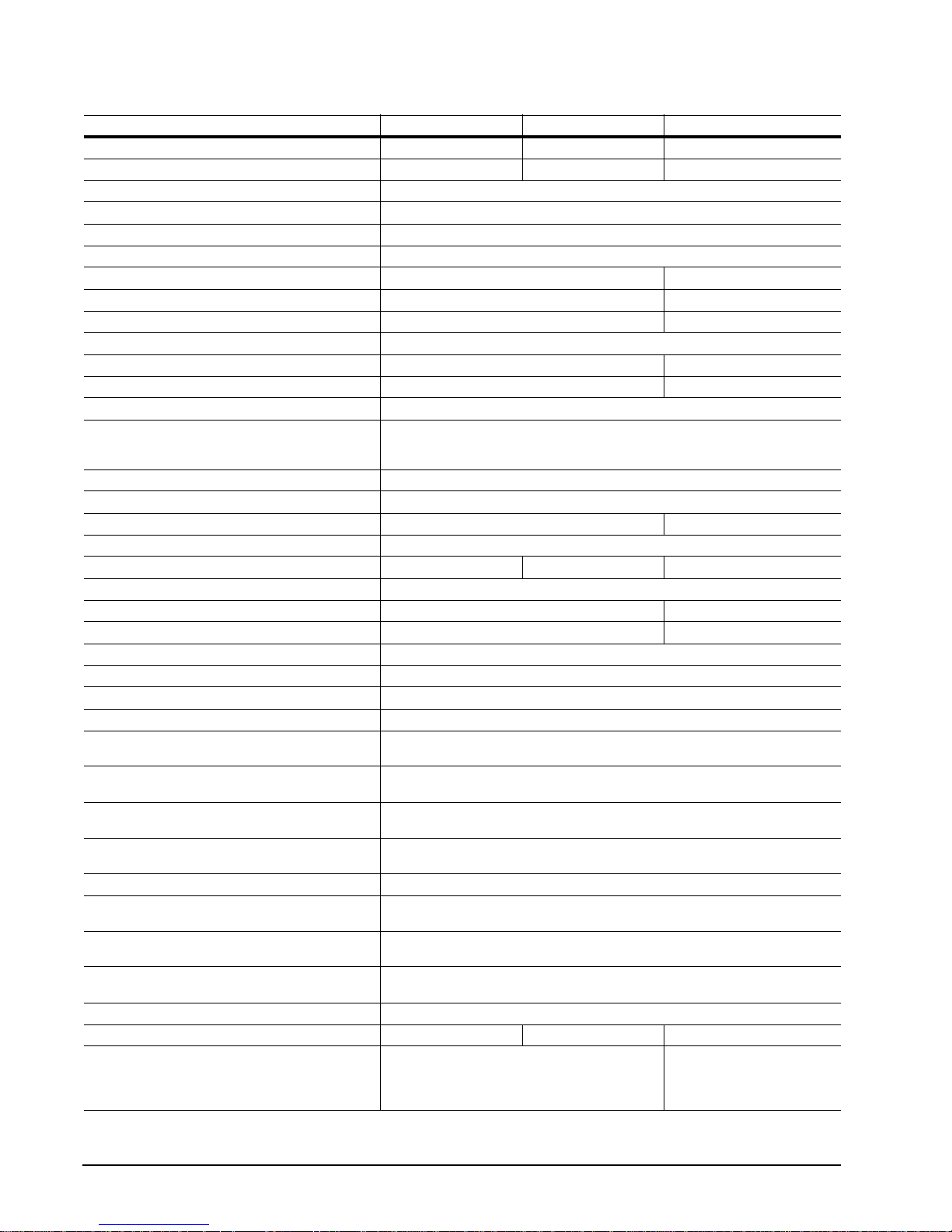
Table 1: Drive specifi cations summary for 300 and 250 Gbyte models
Drive specification STM3300622A STM3250624A STM3250623A
Formatted Gbytes (512 bytes/sector)* 300 250 250
Guaranteed sectors 586,072,368 488,397,168 488,397,168
Bytes per sector 512
Default sectors per track 63
Default read/write heads 16
Default cylinders 16,383
Recording density 790.1 kbits/in max 763 kbits/in max
Track density 124.5 ktracks/in avg 120 ktracks/in avg
Areal density 97.69 Gbits/in
Spindle speed 7,200 RPM
Internal data transfer rate 867.2 Mbits/sec max 760 Mbits/sec max
Sustained data transfer rate OD 76.6 Mbytes/sec max 65 Mbytes/sec max
I/O data-transfer rate 100 Mbytes/sec max
ATA data-transfer modes supported PIO modes 0–4
Cache buffer 16 Mbytes
Height (max) 26.11 mm (1.028 inches)
Width (max) 101.6 mm (4.000 inches) +/- 0.010 inches 101.85 mm (4.010 inches)
Length (max) 146.99 mm (5.787 inches)
Weight (max) 655 grams (1.44 lb.) 580 grams (1.28 lb.) 635 grams (1.39 lb.)
Average latency 4.16 msec
Power-on to ready (max) 11.0 sec 10.0 sec
Standby to ready (max) 11.0 sec 10.0 sec
Track-to-track seek time <0.8 msec typical (read), <1.0 msec typical (write)
Average seek, read <11.0 msec typical)
Average seek, write <12.0 msec typical)
Startup current (typical) 12V (peak) 2.8 amps
Voltage tolerance (including noise) 5V ± 5%
Ambient temperature 0° to 60°C (operating)
Temperature gradient 20°C per hour max (operating)
Relative humidity 5% to 90% (operating)
Relative humidity gradient 30% per hour max
Wet bulb temperature 37.7°C max (operating)
Altitude, operating –60.96 m to 3,048 m
Altitude, nonoperating
(below mean sea level, max)
Operational Shock 63 G max at 2 msec
Non-Operational Shock 300 G max at 2 msec 350 G max at 2 msec 300 G max at 2 msec
Vibration, operating 5–22 Hz: 0.25 G, Limited displacement
Multiword DMA modes 0–2
Ultra DMA modes 0–5
12V ± 10%
–40° to 70°C (nonoperating)
30°C per hour max (nonoperating)
5% to 95% (nonoperating)
40.0°C max (nonoperating)
(–200 ft. to 10,000+ ft.)
–60.96 m to 12,192 m
(–200 ft. to 40,000+ ft.)
22–350 Hz: 0.5 G
350–500 Hz: 0.25 G
2
avg 91.56 Gbits/in2 avg
5–22 Hz:
Limited displacement
23–350 Hz:
0.5 G acceleration
4 DiamondMax 20 PATA Product Manual, Rev. A
Page 13
Drive specification STM3300622A STM3250624A STM3250623A
Vibration, nonoperating 5–22 Hz: 0.25 G, Limited displacement
Drive acoustics, sound power (Bels)
Idle** 2.7 (typical)
Quiet seek 3.0 (typical)
Nonrecoverable read errors 1 per 10
Annualized Failure Rate (AFR) 0.34%
Warranty 3 years on distribution units.
Contact start-stop cycles 50,000 at 25°C, 50% rel. humidity
*One Gbyte equals one billion bytes when referring to hard drive capacity. Accessible capacity may vary depending on operating environment
and formatting.
**During periods of drive idle, some offline activity may occur according to the S.M.A.R.T. specification, which may increase acoustic and
power to operational levels.
22–350 Hz: 5.0 G
350–500 Hz: 1.0 G
2.9 (max)
3.2 (max)
14
bits read
To determine the warranty for a specific drive, use a web browser to access the
following web page:
www.seagate.com/support/service/
From this page, click on the “Verify Your Warranty” link. You will be asked to provide the drive serial number, model number (or part number) and country of purchase. The system will display the warranty information for your drive.
2.7 (typical)
2.9 (max)
3.0 (typical)
3.2 (max)
5–22 Hz:
Limited displacement
23–350 Hz: 5.0 G
2.8 (typical)
3.4 (max)
3.7 (typical)
3.9
DiamondMax 20 PATA Product Manual, Rev. A 5
Page 14

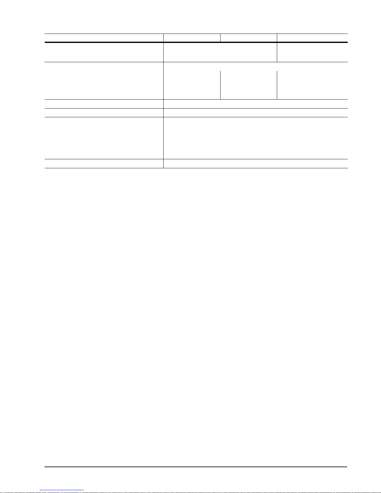
Table 2: Drive specifi cations summary for the 200 Gbyte model
Drive specification STM3200827A
Formatted Gbytes (512 bytes/sector)* 200
Guaranteed sectors 390,721,968
Bytes per sector 512
Default sectors per track 63
Default read/write heads 16
Default cylinders 16,383
Recording density 790.1 kbits/in max
Track density 124.5 ktracks/in avg
Areal density 97.69 Gbits/in
Spindle speed 7,200 RPM
Internal data transfer rate 867.2 Mbits/sec max
Sustained data transfer rate OD 76.6 Mbytes/sec max
I/O data-transfer rate 100 Mbytes/sec max
ATA data-transfer modes supported PIO modes 0–4
Cache buffer 8 Mbytes
Height (max) 26.1 mm (1.028 inches)
Width (max) 101.6 mm (4.000 inches) +/- 0.010 inches
Length (max) 146.99 mm (5.787 inches)
Weight (max) 580 grams
Average latency 4.16 msec
Power-on to ready (max) 11 sec
Standby to ready (max) 11 sec
Track-to-track seek time <0.8 msec typical (read), <1.0 msec typical (write)
Average seek, read (typical) <11.0 msec
Average seek, write (typical) <12.0 msec
Startup current (typical) 12V (peak) 2.8 amps
Voltage tolerance (including noise) 5V ± 5%
Ambient temperature 0° to 60°C (operating)
Temperature gradient 20°C per hour max (operating)
Relative humidity 5% to 90% (operating)
Relative humidity gradient 30% per hour max
Wet bulb temperature 37.7°C max (operating)
Altitude, operating –60.96 m to 3,048 m
Altitude, nonoperating
(below mean sea level, max)
Operational Shock 63 G max at 2 msec
Non-Operational Shock 350 G max at 2 msec
Vibration, operating 5–22 Hz: 0.25 G, Limited displacement
Multiword DMA modes 0–2
Ultra DMA modes 0–5
12V ± 10%
–40° to 70°C (nonoperating)
30°C per hour max (nonoperating)
5% to 95% (nonoperating)
40.0°C max (nonoperating)
(–200 ft. to 10,000+ ft.)
–60.96 m to 12,192 m
(–200 ft. to 40,000+ ft.)
22–350 Hz: 0.50 G
350–500 Hz:: 0.25 G
2
avg
6 DiamondMax 20 PATA Product Manual, Rev. A
Page 15
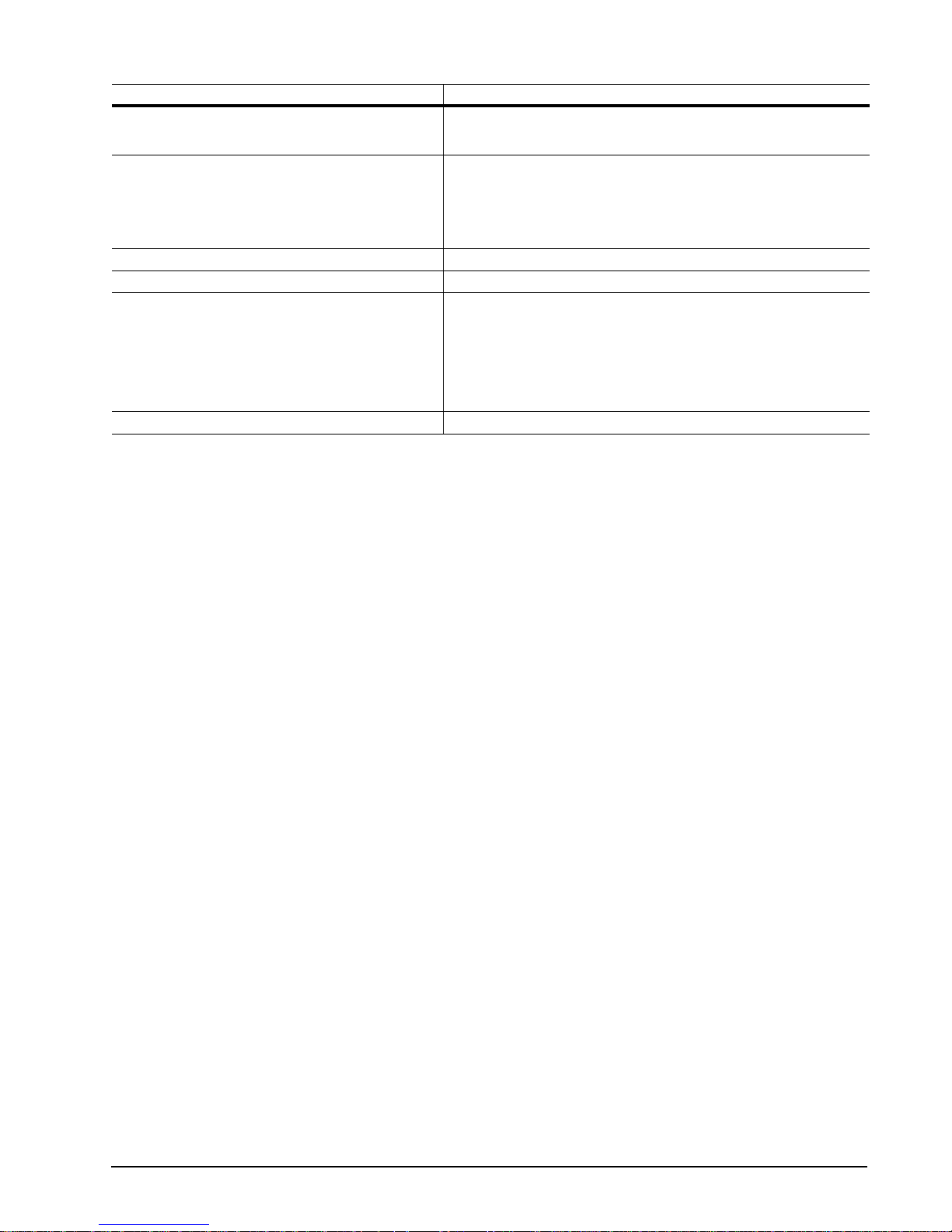
Drive specification STM3200827A
Vibration, nonoperating 5–22 Hz: 0.25 G, Limited displacement
Drive acoustics, sound power (Bels)
Idle** 2.7 (typical)
Quiet seek 3.0 (typical)
Nonrecoverable read errors 1 per 10
Annualized Failure Rate (AFR) 0.34%
Warranty 3 years on distribution units.
Contact start-stop cycles 50,000 at 25°C, 50% rel. humidity
*One Gbyte equals one billion bytes when referring to hard drive capacity. Accessible capacity may vary depending on operating environment
and formatting.
**During periods of drive idle, some offline activity may occur according to the S.M.A.R.T. specification, which may increase acoustic and
power to operational levels.
22–350 Hz: 5.0 G
350–500 Hz:: 1.0 G
2.9 (max)
3.2 (max)
14
bits read
To determine the warranty for a specific drive, use a web browser to
access the following web page:
www.seagate.com/support/service/
From this page, click on the “Verify Your Warranty” link. You will be asked
to provide the drive serial number, model number (or part number) and
country of purchase. The system will display the warranty information for
your drive.
DiamondMax 20 PATA Product Manual, Rev. A 7
Page 16

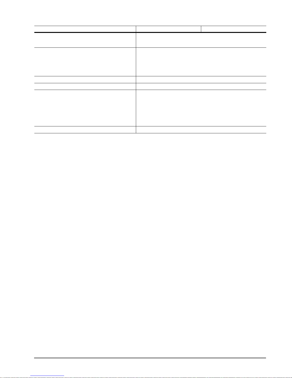
Table 3: Drive specifi cations summary for the 160 Gbyte models
Drive specification STM3160812A STM3160212A
Formatted Gbytes (512 bytes/sector)* 160
Guaranteed sectors 312,581,808
Bytes per sector 512
Default sectors per track 63
Default read/write heads 16
Default cylinders 16,383
Recording density 840.0 kbits/in max
Track density 141.5 ktracks/in avg
Areal density 119. 0 Gbit s/in
Spindle speed 7,200 RPM
Internal data transfer rate 867.2 Mbits/sec max
Sustained data transfer rate OD 83.0 Mbytes/sec max
I/O data-transfer rate 100 Mbytes/sec max
ATA data-transfer modes supported PIO modes 0–4
Cache buffer 8 Mbytes 2 Mbytes
Height (max) 26.1 mm (1.028 inches)
Width (max) 101.6 mm (4.000 inches) +/- 0.010 inches
Length (max) 146.99 mm (5.787 inches)
Weight (max) 580 grams (1.28 lb.)
Average latency 4.16 msec
Power-on to ready (max) <10.0 sec
Standby to ready (max) <10.0 sec
Track-to-track seek time <0.8 msec typical (read), <1.0 msec typical (write)
Average seek, read (typical) <11.0 msec
Average seek, write (typical) <12.0 msec
Startup current (typical) 12V (peak) 2.8 amps
Voltage tolerance (including noise) 5V ± 5%
Ambient temperature 0° to 60°C (operating)
Temperature gradient 20°C per hour max (operating)
Relative humidity 5% to 90% (operating)
Relative humidity gradient 30% per hour max
Wet bulb temperature 37.7°C max (operating)
Altitude, operating –60.96 m to 3,048 m
Altitude, nonoperating
(below mean sea level, max)
Operational Shock 63 G max at 2 msec
Non-Operational Shock 350 G max at 2 msec
Vibration, operating 5–22 Hz: 0.25 G, Limited displacement
Multiword DMA modes 0–2
Ultra DMA modes 0–5
12V ± 10%
–40° to 70°C (nonoperating)
30°C per hour max (nonoperating)
5% to 95% (nonoperating)
40.0°C max (nonoperating)
(–200 ft. to 10,000+ ft.)
–60.96 m to 12,192 m
(–200 ft. to 40,000+ ft.)
22–350 Hz: 0.50 G
350–500 Hz:: 0.25 G
2
avg
8 DiamondMax 20 PATA Product Manual, Rev. A
Page 17
Drive specification STM3160812A STM3160212A
Vibration, nonoperating 5–22 Hz: 0.25 G, Limited displacement
Drive acoustics, sound power (Bels)
Idle** 2.5 (typical)
Quiet seek 2.8 (typical)
Nonrecoverable read errors 1 per 10
Annualized Failure Rate (AFR) 0.34%
Warranty 3 years on distribution units.
Contact start-stop cycles 50,000 at 25°C, 50% rel. humidity
*One Gbyte equals one billion bytes when referring to hard drive capacity. Accessible capacity may vary depending on operating environment
and formatting.
**During periods of drive idle, some offline activity may occur according to the S.M.A.R.T. specification, which may increase acoustic and
power to operational levels.
22–350 Hz: 5.0 G
350–500 Hz:: 1.0 G
2.7 (max)
3.0 (max)
14
bits read
To determine the warranty for a specific drive, use a web browser to
access the following web page:
www.seagate.com/support/service/
From this page, click on the “Verify Your Warranty” link. You will be asked
to provide the drive serial number, model number (or part number) and
country of purchase. The system will display the warranty information for
your drive.
DiamondMax 20 PATA Product Manual, Rev. A 9
Page 18

Table 4: Drive specifi cations summary for the 80 and 40 Gbyte models
Drive specification STM3802110A STM3402111A
Formatted Gbytes (512 bytes/sector)* 80 40
Guaranteed sectors 156,301,488 78,165,360
Bytes per sector 512
Default sectors per track 63
Default read/write heads 16
Default cylinders 16,383
Recording density 840.0 kbits/in max 611.5 kbits/in max
Track density 141.5 ktracks/in avg 103.9 ktracks/in avg
Areal density 119. 0 Gbit s/in
Spindle speed 7,200 RPM
Internal data transfer rate 867.2 Mbits/sec max
Sustained data transfer rate OD 83.0 Mbytes/sec max 69.4 Mbytes/sec max
I/O data-transfer rate 100 Mbytes/sec max
ATA data-transfer modes supported PIO modes 0–4
Cache buffer 2 Mbytes
Height (max) 26.1 mm (1.028 inches)
Width (max) 101.6 mm (4.000 inches) +/- 0.010 inches
Length (max) 146.99 mm (5.787 inches)
Weight (max) 580 grams (1.28 lb.) 525 grams (1.16 lb.)
Average latency 4.16 msec
Power-on to ready (max) <10.0 sec
Standby to ready (max) <10.0 sec
Track-to-track seek time <0.8 msec typical (read), <1.0 msec typical (write)
Average seek, read (typical) <11.0 msec
Average seek, write (typical) <12.0 msec
Startup current (typical) 12V (peak) 2.8 amps
Voltage tolerance (including noise) 5V ± 5%
Ambient temperature 0° to 60°C (operating)
Temperature gradient 20°C per hour max (operating)
Relative humidity 5% to 90% (operating)
Relative humidity gradient 30% per hour max
Wet bulb temperature 37.7°C max (operating)
Altitude, operating –60.96 m to 3,048 m
Altitude, nonoperating
(below mean sea level, max)
Operational Shock 63 G max at 2 msec
Non-Operational Shock 350 G max at 2 msec
Vibration, operating 5–22 Hz: 0.25 G, Limited displacement
Multiword DMA modes 0–2
Ultra DMA modes 0–5
12V ± 10%
–40° to 70°C (nonoperating)
30°C per hour max (nonoperating)
5% to 95% (nonoperating)
40.0°C max (nonoperating)
(–200 ft. to 10,000+ ft.)
–60.96 m to 12,192 m
(–200 ft. to 40,000+ ft.)
22–350 Hz: 0.50 G
350–500 Hz:: 0.25 G
2
avg 63..53 Gbits/in2 avg
10 DiamondMax 20 PATA Product Manual, Rev. A
Page 19

Drive specification STM3802110A STM3402111A
Vibration, nonoperating 5–22 Hz: 0.25 G, Limited displacement
Drive acoustics, sound power (Bels)
Idle** 2.5 (typical)
Quiet seek 2.7 (typical)
Nonrecoverable read errors 1 per 10
Annualized Failure Rate (AFR) 0.34%
Warranty 3 years on distribution units.
Contact start-stop cycles 50,000 at 25°C, 50% rel. humidity
*One Gbyte equals one billion bytes when referring to hard drive capacity. Accessible capacity may vary depending on operating environment
and formatting.
**During periods of drive idle, some offline activity may occur according to the S.M.A.R.T. specification, which may increase acoustic and
power to operational levels.
22–350 Hz: 5.0 G
350–500 Hz:: 1.0 G
2.7 (max)
2.9 (max)
14
bits read
To determine the warranty for a specific drive, use a web browser to
access the following web page:
www.seagate.com/support/service/
From this page, click on the “Verify Your Warranty” link. You will be asked
to provide the drive serial number, model number (or part number) and
country of purchase. The system will display the warranty information for
your drive.
2.0 (typical)
2.3 (max)
2.4 (typical)
2.6 (max)
DiamondMax 20 PATA Product Manual, Rev. A 11
Page 20

2.2 Formatted capacity
Formatted
Model
STM3300622A 300 Gbytes 586,072,368 512
STM3250623A 250 Gbytes 488,397,168 512
STM3250624A 250 Gbytes 488,397,168 512
STM3200827A 200 Gbytes 390,721,968 512
STM3160212A 160 Gbytes 312,581,808 512
STM3160812A 160 Gbytes 312,581,808 512
STM3802110A 80 Gbytes 156,301,488 512
STM3402111A 40 Gbytes 78,165,360 512
*One Gbyte equals one billion bytes when referring to hard drive capacity. Accessible capacity may va ry depending on op erating environment and formatting.
capacity*
Guaranteed
sectors Bytes per sector
2.2.1 LBA mode
When addressing these d rives in LBA mode, all bl ocks (sectors) are cons ecutively numbered fr om 0 to n–1,
where n is the number of guaranteed sectors as defined above.
See Section 4.1.2, "Id enti fy Devic e co mma nd" (w ords 60 -6 1 a nd 1 00- 10 3) for a ddi tio nal in formation about 48bit addressing support of drives with capacities over 137 Gbytes.
2.3 Default logical geometry
Cylinders Read/write heads Sectors per track
16,383 16 63
12 DiamondMax 20 PATA Product Manual, Rev. A
Page 21

2.4 Recording and interface technology
STM3300622A
STM3250624A
STM3200827A STM3250623A
Interface ATA
Recording density, KBPI (kbits/inch max) 790.1 763 840.0 611.5
Track density, KTPI (ktracks/inch avg) 124.5 120 141.5 103.9
2
Areal density (Gbits/inch
Spindle speed (RPM) (± 0.2%) 7,200
Internal data transfer rate (Mbits/sec max) 867.2 760 867.2 867.2
Sustained data transfer rate
(Mbytes/sec max)
I/O data-transfer rate (Mbytes/sec max) 100 (Ultra DMA mode 5)
avg) 97.69 91.56 119.0 63.53
76.6 65.0 83.0 69.4
STM3160212A
STM3160812A
STM3802110A STM3402111A
2.5 Physical characteristics
Drive specification
Maximum height
(mm)
(inches)
Maximum width
(mm)
(inches)
26.11
1.028
101.6
4.000 +/- 0.010
Maximum lengt h
(mm)
(inches)
Max weight
STM3300622A
STM3250623A
STM3250624A
STM3200827A
STM3160812A
STM3160212A
STM3802110A
STM3402111A
Cache Size
STM3300622A
STM3250623A
STM3250624A
STM3200827A
STM3160812A
STM3160212A
STM3802110A
STM3402111A
146.99
5.787
655 grams (1.44 lbs)
635 grams (1.39 lbs)
580 grams (1.28 lbs)
580 grams (1.28 lbs)
580 grams (1.28 lbs)
580 grams (1.28 lbs)
580 grams (1.28 lbs)
525 grams (1.16 lbs)
16 Mbytes
16 Mbytes
16 Mbytes
8 Mbytes
8 Mbytes
2 Mbytes
2 Mbytes
2 Mbytes
2.6 Seek time
Seek measurements are taken with nominal power at 25°C ambient temperature. All times are measured using
drive diagnostics. The specifications in the table below are defined as follows:
DiamondMax 20 PATA Product Manual, Rev. A 13
Page 22

• Track-to-track seek time is an average of all possible single-track seeks in both directions.
• Average seek time is a true statistical random av erage of at least 5,000 measurements of seeks betwee n
random tracks, less overhead.
*Typical seek times (msec) Read Write
Track-to-track <0.8 <1.0
Average <11.0 <12.0
Average latency 4.16 4.16
*Measured in quiet mode
Note. These drives are designed to consistently meet the seek times represented in this manual. Physical seeks,
regardless of mode (such as track-to-track and average), are expected to meet or exceed the noted values.
However, due to the manner in which these drives are formatted, benchmark tests that include command
overhead or measure logical seeks may produce results that vary from these specifications.
2.7 Start/stop times
STM3300622A STM3250623A All other models
Power-on to Ready (sec) 11 (max) 10 (max) <10 (max)
Standby to Ready (sec) 11 (max) 10 (max) <10 (max)
Ready to spindle stop (sec) 12 (max) 12 (max) <11 (max)
14 DiamondMax 20 PATA Product Manual, Rev. A
Page 23

2.8 Power specifications
The drive receives DC power (+5V or +12V) through a four-pin standard drive power connector.
2.8.1 Power consumption
Power requirements for the dr i ves ar e lis ted i n th e table s beg inn in g o n page 15. Typical power meas ur em ents
are based on an av erage of driv es te sted, under nomin al co nditio ns, u sing +5.0V and + 12.0V input voltage a t
25°C ambient temperature.
• Spinup power
Spinup power is measured from the time of power-on to the time that the drive spindle reaches operating speed.
• Seek mode
During seek mode, the read/write actuator arm moves toward a specific position on the disc surface and does
not execute a read or write operatio n. Se rvo electr onics ar e active. S eek mode power repres ents the worstcase power consump tion, using only random se eks with read or write laten cy time. This mod e is not typic al
and is provided for worst-case information.
• Read/write power and current
Read/write power is me asured with the he ads on track, b ased on a 16-sec tor write followed by a 32-msec
delay, then a 16-sector read followed by a 32-msec delay.
• Operating power and current
Operating power is mea sure d using 40 percent random s eek s, 40 p er cent r ead /write mo de ( 1 wri te fo r e ach
10 reads) and 20 percent drive idle mode.
• Idle mode power
Idle mode power is measur ed wi th th e driv e up to s pee d, wi th ser vo ele ctron ics act ive and with the heads in
a random track location.
• Standby mode
During Standby mode, the driv e accepts commands, but the drive is not spinning, and the ser vo and read/
write electronics are in power-down mode.
T a ble 5: STM3300622A DC power requirements
Power dissipation (watts) Avg (watts, 25° C) Avg 5V typ amps Avg 12V typ amps
Spinup — — 2.80 (peak)
Idle* 7.40 0.393 0.453
Idle* (with offline activity) 9.40 0.483 0.582
Operating (40% r/w, 40% seek, 20% inop.) 13.00 0.811 0.746
Seeking (random, 20% idle) 12.80 0.471 0.870
Standby 0.80 0.112 0.02
Sleep 0.80 0.112 0.02
*During periods of drive idle, some o ffline activity may occur according to th e S.M.A.R.T. specification, which may increase ac oustic and
power to operational levels.
DiamondMax 20 PATA Product Manual, Rev. A 15
Page 24

Table 6: STM3250623A DC power requirements
Power dissipation (watts) Avg (watts, 25° C) Avg 5V typ amps Avg 12V typ amps
Spinup — — 2.80 (peak)
Idle* 7.2 0.401 0.433
Idle* (with offline activity) 9.1 0.78 0.433
Operating (40% r/w, 40% seek, 20% inop.) 12.8 0.841 0.715
Seeking (random, 20% idle) 12.4 0.602 0.782
Standby 0.8 0.145 0.006
Sleep 0.8 0.145 0.006
*During periods of drive idle, some o ffline activity may occur according to the S. M.A.R.T. specification, which may increase acoust ic and
power to operational levels.
Table 7: STM3250624A and STM3200827A DC power requirements
Power dissipation (watts) Avg (watts, 25° C) Avg 5V typ amps Avg 12V typ amps
Spinup — — 2.80 (peak)
Idle* 7.20 0.382 0.441
Idle* (with offline activity) 9.10 0.491 0.554
Operating (40% r/w, 40% seek, 20% inop.) 12.80 0.687 0.781
Seeking (random, 20% idle) 12.40 0.446 0.848
Standby 0.80 0.113 0.020
Sleep 0.80 0.110 0.021
*During periods of drive idle, some o ffline activity may occur according to the S. M.A.R.T. specification, which may increase acoust ic and
power to operational levels.
Table 8: STM3160212A and STM3160812A DC power requirements
Power dissipation (watts) Avg (watts, 25° C) Avg 5V typ amps Avg 12V typ amps
Spinup — — 2.80 (peak)
Idle* 7.20 0.590 0.354
Idle* (with offline activity) 9.10 0.880 0.391
Operating (40% r/w, 40% seek, 20% inop.) 12.80 0.920 0.682
Seeking (random, 20% idle) 12.40 0.690 0.745
Standby 0.80 0.113 0.020
Sleep 0.80 0.113 0.020
*During periods of drive idle, some o ffline activity may occur according to the S. M.A.R.T. specification, which may increase acoust ic and
power to operational levels.
16 DiamondMax 20 PATA Product Manual, Rev. A
Page 25

T able 9: STM3802110A and STM3402111A DC power requirements
Power dissipation (watts) Avg (watts, 25° C) Avg 5V typ amps Avg 12V typ amps
Spinup — — 2.80 (peak)
Idle* 7.00 0.490 0.379
Idle* (with offline activity) 8.90 0.873 0.378
Operating (40% r/w, 40% seek, 20% inop.) 12.60 0.897 0.676
Seeking (random, 20% idle) 12.20 0.627 0.755
Standby 0.80 0.116 0.018
Sleep 0.80 0.116 0.018
*During periods of drive idle, some o ffline activity may occur according to th e S.M.A.R.T. specification, which may increase ac oustic and
power to operational levels.
2.8.1.1 Typical current profile
Figure 1 Typical 5V startup and operation current profile
Figure 2 Typical 12V startup and operation current profile
DiamondMax 20 PATA Product Manual, Rev. A 17
Page 26

2.8.2 Conducted noise
Input noise ripple is mea su red at the ho st system power supply acr o ss an equ iv al ent 80 -ohm r es isti ve load on
the +12 volt line or an equivalent 15-ohm resistive load on the +5 volt line.
• Using 12-volt power, the drive is expected to operate with a maximum of 120 mV peak-to-peak square-wave
injected noise at up to 10 MHz.
• Using 5-volt power, the drive is expect ed to ope rate wi th a max imum of 1 0 0 mV peak -to-peak squa re-wav e
injected noise at up to 10 MHz.
Note. Equival ent resistance is calcul ated by dividing the nomina l voltage by the typical RMS read/write
current.
2.8.3 Voltage tolerance
Voltage tolerance (including noise):
5V ± 5%
12V ± 10%
2.8.4 Power-management modes
The drive provides programmab le power mana gement to provide grea ter energy efficiency. In most systems,
you can control power management through the system setup program. The drive features the following
power-management modes :
Power mode Heads Spindle Buffer
Active Tracking Rotating Enabled
Idle Tracking Rotating Enabled
Standby Parked Stopped Enabled
Sleep Parked Stopped Disabled
• Active mode
The drive is in Active mode during the read/write and seek operations.
• Idle mode
The buffer remains en abled, and the drive a ccepts a ll comm ands and re turns to Ac tive mode any time disc
access is necessary.
• Standby mode
The drive enters Standby mode when the host sends a Standby Immediate command. If the host has set the
standby timer, the dri ve can also enter Stand by mode automaticall y after the drive has be en inactive for a
specifiable length of time. The standby timer delay is established using a Standby or Idle command. In Standby
mode, the drive buffer is enab led, the heads are parked and the spi ndle is at rest. The drive accepts all
commands and returns to Active mode any time disc access is necessary.
• Sleep mode
The drive enters Sleep mode after receiving a Sleep command from the host. In Sleep mode, the drive buffer
is disabled, the he ads are p arke d and the spind le is at rest. T he dr ive leav es Slee p mo de after it rece ives a
Hard Reset or Soft Reset from the host. After receiving a reset, the drive exits Sleep mode and enters Standby
mode with all current translation parameters intact.
• Idle and Standby timers
Each time the drive perfo rms an Active function (read, wr ite or seek), the standby time r is reinitialized and
begins counting down from its specified delay times to zero. If the standby timer reaches zero before any drive
18 DiamondMax 20 PATA Product Manual, Rev. A
Page 27

activity is required, the driv e makes a transi tion to Standb y mode. In both Idle and Standby mode, the d rive
accepts all commands and returns to Active mode when disc access is necessary.
2.9 Environmental specifications
2.9.1 Ambient temperature
Ambient temperature is defined as the temperature of the environment immediately surrounding the drive.
Actual drive case t emperatur e shoul d not excee d
ommended measurement locations are shown in See Figure 6 on page 31.
Above 1,000 feet (305 meters), the ma ximum temperature is derated linearly to 112°F (44°C) at 10,000 feet
(3,048 meters).
Operating: 5° to 60°C (41° to 140°F)
Nonoperating: –40° to 70°C (–40° to 158°F)
2.9.2 Temperature gradient
Operating: 20°C per hour (68°F per hour max), without condensation
Nonoperating: 30°C per hour (86°F per hour max)
2.9.3 Humidity
69°C (1 56°F) within the opera ting ambient conditio ns. Rec-
2.9.3.1 Relative humidity
Operating: 5% to 90% noncondensing (30% per hour max)
Nonoperating: 5% to 95% noncondensing (30% per hour max)
2.9.3.2 Wet bulb temperature
Operating: 37.7°C (99.9°F max)
Nonoperating: 40.0°C (104°F max)
2.9.4 Altitude
Operating: –60.96 m to 3,048 m (–200 ft. to 10,000+ ft.)
Nonoperating: –60.96 m to 12,192 m (–200 ft. to 40,000+ ft.)
DiamondMax 20 PATA Product Manual, Rev. A 19
Page 28

2.9.5 Shock
All shock specificat ions assume that the drive is mou nted securely with the input s hock applied at the drive
mounting screws. Shock may be applied in the X, Y or Z axis.
2.9.5.1 Operating shock
These drives compl y with the performance level s specified in this docu ment when subjected to a ma ximum
operating shock of 63 G based on half-sine shock pulses of 2 msec. Shocks should not be repeated more than
two times per second.
2.9.5.2 Nonoperating shock
The nonoperating s hock l evel that th e driv e can expe rience withou t incur ring ph ysic al d amage or degr adatio n
in performance when subsequently put into operation is 300 G (300GB models), 350 G (250 , 200, 160, 80 and
40GB models) based on a nonrepetitive half-sine shock pulse of 2 msec duration.
2.9.6 Vibration
All vibration spec ifications assume that the drive is mounted securely with the input vibration applied at the
drive mounting screws. Vibration may be applied in the X, Y or Z axis.
2.9.6.1 Operating vibration
The following table lists the maximum vibration lev els that the dri ve may expe rience while meet ing the perfor mance standards specified in this document.
5–22 Hz 0.25 G (limited dis placement)
22–350 Hz 0.50 G
350–500 Hz 0.25 G
2.9.6.2 Nonoperating vibration
The following table l ists the maximum no noperating vibr ation that the drive may expe rience without incurring
physical damage or degradation in performance when subsequently put into operation.
5–22 Hz 0.25 G (limited displacement)
22–350 Hz 5.0 G
350–500 Hz 1.0 G
20 DiamondMax 20 PATA Product Manual, Rev. A
Page 29

2.10 Acoustics
Drive acoustics a re measured as overall A -weighted acoustic soun d power levels (no pu re tones). All measurements are consistent with ISO document 77 79. Sound power measur ements are taken under essential ly
free-field conditions over a reflecting plane. For all tests, the drive is oriented with the cover facing upward.
Note. For seek mode tests, the drive is placed in seek mode only. The number of seeks per second is defined
by the following equation:
(Number of seeks per second = 0.4 / (average latency + average access time)
Table 10: Fluid Dynamic Bearing (FDB) motor acoustics
Acoustic mode
Idle* Quiet seek
STM3300622A 2.7 Bels (typ)
STM3250623A 2.8 Bels (typ)
STM3250624A
STM3200827A
STM3160212A
STM3160812A
STM3802110A 2.5 Bels (typ)
STM3402111A 2.0 Bels (typ)
*During periods of drive idle, some o ffline activity may occur according to th e S.M.A.R.T. specification, which may increase ac oustic and
power to operational levels.
2.9 Bels (max)
3.4 Bels (max)
2.7 Bels (typ)
2.9 Bels (max)
2.5 Bels (typ)
2.7 Bels (max)
2.7 Bels (max)
2.3 Bels (max)
3.0 Bels (typ)
3.2 Bels (max)
3.7 Bels (typ)
3.9 Bels (max)
3.0 Bels (typ)
3.2 Bels (max)
2.8 Bels (typ)
3.0 Bels (max)
2.7 Bels (typ)
2.9 Bels (max)
2.4 Bels (typ)
2.6 Bels (max)
DiamondMax 20 PATA Product Manual, Rev. A 21
Page 30

2.11 Electromagnetic immunity
When properly installed in a representative host system, the drive operates without err ors or degradation in
performance when subjected to the radio frequency (RF) environments defined in the following table:
Table 11: Radio frequency environments
Test Description
Electrostatic discharg e Con t ac t, HCP, VCP: ± 4
± 8 kV
Radiated RF immunity 80 to 1,000 MHz, 3 V/m,
80% AM with 1 kHz sine
900 MHz, 3 V/m, 50% pulse
modulation @ 200 Hz
Electrical fast transient ± 1 kV on AC mains , ± 0.5 kV on
external I/O
Surge immunity ± 1 kV different ial, ± 2 kV com-
mon, AC mains
Conducted RF immunity 150 kHz to 80 MHz, 3 Vrms,
80% AM with 1 kHz sine
Voltage dips, interrupts 0% open, 5 seconds
0% short, 5 seconds
40%, 0.10 seconds
70%, 0.01 seconds
kV; Air:
Performance
level
B EN 61000-4-2: 95
A EN 61000-4-3: 96
B EN 61000-4-4: 95
B EN 61000-4-5: 95
A EN 61000-4-6: 97
C
C
C
B
Reference
standard
ENV 50204: 95
EN 61000-4-11: 94
22 DiamondMax 20 PATA Product Manual, Rev. A
Page 31

2.12 Reliability
2.12.1 Annualized Failure Rate (AFR and Mean Time Between Failures (MTBF)
The product shall achieve an Ann ual iz ed Fai lu re Rate ( AFR) of 0.3 4% (MT BF of 0.7 milli on ho urs) whe n operated in an environment of am bient air temp eratures of 25
tions in Section 2.9 ma y inc reas e the pr oduc t A FR (decr ea se MTBF ). AF R a nd MT B F ar e pop ula tio n sta tisti cs
that are not relevant to individual units.
AFR and MTBF specifications are based on the following assumptions for desktop personal computer environments:
• 2400 power-on-hours per year.
• 10,000 average motor start/stop cycles per year.
• Operations at nominal voltages.
• Temperatures outside the specifications in Section 2.9 may reduce the product reliability.
• Normal I/O duty cycle for de sktop pe rsonal compu ters. Oper ation at ex cessive I/O duty cyc le may degrad e
product reliability.
The desktop personal c omputer environment of oower-on-hours , temperature, and I/O duty cycle affect the
product AFR and MTBF. The AFR and MTBF will be degraded if used in a enterprise application.
Nonrecov erable read errors 1 per 1014 bits read, max
Annualized Failure Rate (AFR) 0.34% (nominal power, 25°C ambient temperature)
°C. Operation at temperat ures outside the s pecifica-
Contact start-stop cycles 50,000 cycles
Warranty 3 years on distributi on units.
Preventive maintenance None required.
(at nominal voltage and temperature, with 60 cycles per hour and a 50% duty cycle)
To determine the warranty for a specific drive, use a web browser to access the following web page:
www.seagate.com/support/service/
From this page, click on the “Verify Your Warranty” link. You will be asked to provide
the drive serial number, model number (or part number) and country of purchase.
The system will display the warranty information for your drive.
2.13 Agency certification
2.13.1 Safety certification
The drives are recogni ze d in ac co rd anc e with UL 1950 and CSA C22.2 (950) and meet all applicab le s ec ti ons
of IEC950 and EN 60950 as tested by TUV North America.
2.13.2 Electromagnetic compatibility
Hard drives that display the CE mark comply with the European Union (EU) requirements specified in the Electromagnetic Compatibili ty Directive (89/336/EE C). Testing is performed to the l evels specified by the product
standards for Information Technology Equipment (ITE). Emission levels are defined by EN 55022, Class B and
the immunity levels are defined by EN 55024.
Seagate uses an independent laboratory to confirm compliance with the EC directives specified in the previous
paragraph. Drives are tested in representative end-user systems. Although CE-marked Seagate drives comply
with the directives wh en used in the test systems, we cannot guarantee t hat all systems will comply wit h the
DiamondMax 20 PATA Product Manual, Rev. A 23
Page 32

directives. The drive is designed for operation inside a properly designed enclosure, with properly shielded I/O
cable (if necessary) and termi nators on all unu sed I/O ports. Compute r manufacture rs and system inte grators
should confirm EMC compliance and provide CE marking for their products.
Korean RRL
If these drives have the Korea M inistry of Information a nd Comm unication ( MIC) logo , they co mply with paragraph 1 of Article 11 of the Electromagnetic Compatibili ty control Regulation and meet the Electr omagnetic
Compatibility (EMC) Framework req ui remen ts of the Radio Res earc h Labo rator y (RRL) Minis try of Infor ma tio n
and Communication Republic of Korea.
These drives have been tested and comply with the Electromagnetic Interference/Electromagnetic Susceptibility (EMI/EMS) for Class B products. Drives are tested in a representative, end-user system by a Korean-recognized lab.
• Family name: DiamondMax
• Certificate number: Pending
Australian C-Tick (N176)
If these models h ave the C-Tick marki ng, th ey com ply wi th the Aus tralia/N ew Z ealand Standard AS/NZS 3548
1995 and meet the Electromagnetic Compatibility (EMC) Framework requirements of the Australian Communication Authority (ACA).
2.13.3 FCC verification
These drives are intended to be contained solely within a personal computer or similar enclosure (not attached
as an external device). As such, each drive is considered to be a subassembly even when it is individually marketed to the customer. As a subassembly, no Federal Communications Commission verificati on or certification
of the device is required.
Seagate Technology LLC has tested this device in enclosures as described above to ensure that the total
assembly (enclosure, dis c drive, motherboard, power supply, etc.) does comply with the limits for a Class B
computing device , pursuant to Subpa rt J, Part 15 of the FCC ru les. Opera tion with nonce rtified assem blies is
likely to result in interference to radio and television reception.
Radio and television interference. This equipment generates and uses radio frequency energy and if not
installed and used in strict accordance with th e manufacturer ’s instructions, may cause i nterference to radio
and television reception.
This equipment is designed to provide reasonable protection against such interference in a residential installation. However, there is no guarantee that interference will not occur in a particular installation. If this equipment
does cause interfer ence to radio or te levision, whic h can be determi ned by turning t he equipment on and off,
you are encouraged to try one or more of the following corrective measures:
• Reorient the receiving antenna.
• Move the device to one side or the other of the radio or TV.
• Move the device farther away from the radio or TV.
• Plug the computer into a different outlet so that the receiver and computer are on different branch outlets.
If necessary, you should consult your dealer or an experienced radio/tel evision technician for additional sug-
gestions. You may find helpful the following booklet prepared by the Federa l Communications Commission:
How to Identify and Resolve Radio-Television Interference Problems. This booklet is available from the Superintendent of Documents, U.S. Gov ernment Printing Office, Washington, DC 20 402. Refer to public ation number 004-000-00345-4.
24 DiamondMax 20 PATA Product Manual, Rev. A
Page 33

2.14 Environmental protection
Seagate designs its prod ucts to meet environ mental protectio n requirem ents worldwide, in cluding regul ations
restricting certain chemical substances.
2.14.1 European Union Restriction of Hazardous Substances (RoHS)
The European Union Restriction of Hazardous Substances (RoHS) Directive restricts the presence of chemical
substances, including Lead (Pb), in electronic products effective July 2006. Although amendments to the
Euro-pean Union’s Restri ction of Hazardous Substances (Ro HS) Dire cti ve ha ve not bee n finalized, to the best
of our knowledge the disc drives documented in this publication will comply with the final RoHS Directive
require-ments.
A number of parts and materials in Seag ate products are procured from external suppl iers. We rely on the
rep-resentations of our suppliers regarding the presence of RoHS substances in these parts and materials. Our
supplier contracts r equire compliance with our chem ical substance restrictions, a nd our suppliers document
their compliance with our requirements by providing material content declarations for all parts and materials for
the disc drives documented in this publication. Current supplier declarations include disclosure of the inclusion
of any RoHS-regulated substance in such parts or materials.
Seagate also has internal systems in place to ensure ongoing compliance with the RoHS Directive and all laws
and regulations which restrict chemical content in electronic products. These systems include standard
operat-ing procedures that ensure that restricted su bstances are not utiliz ed in our manufacturi ng operations,
labora-tory analyti cal validatio n testing, and an internal auditing pr ocess to ens ure that all standar d operatin g
procedures are complied with.
2.15 Corrosive environment
Seagate electronic driv e components pass accelerated corr osion testing equivalent to 10 ye ars exposure to
light industrial envir onments containi ng sulfuro us gases, chlorine an d nitric oxide , classes G and H per ASTM
B845. However, this accelerated testing cannot duplicate every potential application environment. Users
should use caution exposing any electronic components to uncontrolled chemical pollutants and corrosive
chemicals as elec tronic drive componen t reliabi lity ca n be affected by th e installati on environm ent. The s ilver,
copper, nickel and gold films used in Seagate products are especially sensitive to the presence of sulfide, chloride, and nitrate contaminants. Sulfur is found to be the most damaging. In addition, electr onic components
should never be ex pose d to c ondensin g water on the surfac e of th e pri nted cir cuit bo ard a ssembly (PCBA ) or
exposed to an ambient relative humidity greater than 95%. Materials used in cabinet fabrication, such as vulcanized rubber, that can outgas corr osive compoun ds should be m inimized or e liminated. Th e useful life of any
electronic equipment may be extended by replacing materials near circuitry with sulfide-free alternatives.
DiamondMax 20 PATA Product Manual, Rev. A 25
Page 34

26 DiamondMax 20 PATA Product Manual, Rev. A
Page 35

3.0 Configuring and mounting the drive
This section contains the specifications and instructions for configuring and mounting the drive.
3.1 Handling and static discharge precautions
After unpacking, and before installation, the dr ive may be ex posed to pote ntial handli ng and electros tatic discharge (ESD) hazards. Observe the following standard handling and static-discharge precautions:
Caution:
• Before handling the drive, put on a grounded wrist strap, or ground yourself frequently by touching the metal
chassis of a com puter that is plugge d into a grounded outl et. Wear a grounded wris t strap throughout th e
entire installation procedure.
• Handle the drive by its edges or frame only.
• The drive is extremely fragile—handle it with care. Do not press down on the drive top cover.
• Always rest the drive on a padded, antistatic surface until you mount it in the computer.
• Do not touch the connector pins or the printed circuit board.
• Do not remove the factory-installed labels from the drive or cover them with additional labels. Removal voids
the warranty. Some factory-installed labels co ntain in for ma tio n nee ded to service the drive . O ther l abe ls ar e
used to seal out dirt and contamination.
DiamondMax 20 PATA Product Manual, Rev. A 27
Page 36

3.2 Breather filter hole precautions
This section contains information regarding the precautions which should be taken regarding the breather filter
hole in Seagate hard d isc drives. Prop er precautions should be taken to en sure full functio nality and preven t
possible damage to the drive.
Breather hole
Do not cover or seal
this hole.
Figure 3 Breather filter hole location
Caution: Do not cover, seal, or insert any object into this h ole.
This hole has two purposes:
• To allow condensation inside the hard disc to escape
• To allow air pressure inside the hard disc to equalize with ambient pressure
Note. If this hole is covered, sealed, or penetrated by any object, the drive reliability may be compromised
and could lead to permanent damage. Covering or sealing this hole voids the warranty.
28 DiamondMax 20 PATA Product Manual, Rev. A
Page 37

3.3 Jumper settings
Options jumper block
3.3.1 Master/slave configuration
The options jumper b lock shown in Figure 4 is used to configure the drive for operatio n. It is the 8-pin dual
header between the in terface connec tor and the power connector. Use the following settings to con figure the
drive as a master or a slave.
Master or single drive. The drive is configured at the factor y for a master or single-drive operation with a
jumper set on pins 7 and 8.
Drive as slave. Remove all jumpers.
Drive as master with a non-ATA-compatible slave.
Use this jumper setting only if the drive does not work as a master with no jumpers installed.
*Master or single drive
Drive is slave
Master with non ATA-
compatible slave
*Cable select
1753
684
2
Figure 4 Master/slave jumper settings
3.3.2 Cable select option
Computers that use cable select det ermine the master and slave drives by selecting or dese lecting pin 28,
CSEL, on the interface bus. Master and slav e dr ives are det ermi ned by their phys ical pos i tio n on the cab le. To
enable cable selec t, set a jumper on pins 5 and 6 as shown i n Figure 4. Refer to your computer manual to
determine whether your computer supports this option.
DiamondMax 20 PATA Product Manual, Rev. A 29
Page 38

3.3.3 Ultra ATA/100 cable
An 80-conductor 40 -pin cable is required to run Ultra DMA mode 3, mode 4, and mode 5. This cable uses
even-numbered conductors connected to the ground pins to improve signal integrity.
Note.
If you are using a 40-pin, 80-conductor
cable, attach the blue connector to the
motherboard, the black connector to the
master drive, and the gray connector
to the slave.
Master
Slave
Figure 5 Ultra ATA cable connectors
Pin 1
Computer
Motherboard
Note. The drive supports both host and drive cable detection. The host detects the 80-conductor cable by
sampling pin 34, CBLID–, on the interface bus . The drive detec ts the 80-conduc tor cable by sensing a capacitor at the host side thr ough the CBLID– signal. The result is repor ted in a Fast Rise
Detected bit (bit 13 of word 93 in the Identify drive parameter block).
3.4 Drive mounting
You can mount the driv e in any o rientation u sing four screws in the s ide-mountin g hole s or four screws i n the
bottom-mounting holes. See Figure 6 for drive mounting dimensions. Follow these important mounting precautions when mounting the drive:
• Allow a minimum clearance of 0.030 inches (0.76 mm) around the entire perimeter of the drive for cooling.
• Use only 6-32 UNC mounting screws.
• Do not overtighten the mounting screws (maximum torque: 6 inch-lb.).
• Do not use a drive interface cable that is more than 18 inches long.
30 DiamondMax 20 PATA Product Manual, Rev. A
Page 39

Notes:
1. Dimensions are shown in inches (mm).
R
c
m
er
2 Dimensions per SFF-8301 specification.
ecommended
ase temperature
easurement location
1.028 max
(26.11)
3 x 0.25 0.010
(6.35 0.037)
both sides
1.122 0.02
(28.5 0.51)
1.638 0.01
(41.61 0.25)
3 x 6-32 UNC-2B
0.150 (3.81) max. fastener
penetration both sides. 3 threads
minimum engagement.
2
5.787 max
(146.99)
4.0 0.01
(101.60 0.25)
0.228
(5.79)
2.23
(56.56)
2.83
(71.80)
3.71
(94.35)
0.125 0.01
(3.18 0.25)
3.750 0.01
(95.25 0.25)
4.0 0.01
(101.60 0.25)
0.178
(4.27)
1.625 0.020
(41.28 0.51)
1.75 0.01
(44.45 0.25)
4 x 6-32 UNC-2B
0.150 (3.81) max. fasten
penetration. 3 threads
minimum engagement.
Recommended
case temperature
measurement location
Figure 6 Mounting dimensions
DiamondMax 20 PATA Product Manual, Rev. A 31
Page 40

32 DiamondMax 20 PATA Product Manual, Rev. A
Page 41

r
Host pin # and signal description
Drive pin #
).
4.0 ATA interface
These drives use t he industry-standard ATA task file interface that s upports 16-bit data transfer s. It supports
ATA programmed input/output (PIO) modes 0–4; m ultiwor d DMA m odes 0– 2, and Ul tra DMA mod es 0–5. The
drive also supports the use of the IORDY signal to provide reliable high-speed data transfers.
You can use a daisy-chai n cabl e to co nnect two drive s to a single AT host bus. For detailed i nform ation about
the ATA interfa ce, refer to the draft of AT Attachment with Packet Interface Extensi on (ATA/ATAPI-7), NCITS
T13 1410D, subsequently referred to as the Draft ATA-7 Standard.
4.1 ATA interface signals and connector pins
Figure 7 on page 33 summarizes the signal s on the ATA interface connector that the drive supports. For a
detailed description of these signals, refer to the Draft A TA-7 Standard.
Signal name
–
1
2
3
4
5
6
7
8
9
10
11
12
13
14
15
16
17
18
19
20
21
22
23
24
25
26
27
28
29
30
31
32
33
34
35
36
37
38
39
40
Pins 28, 34 and 39 are used for master-slave communication (details shown below
28
34
39
Reset
Ground
DD7
DD8
DD6
DD9
DD5
DD10
DD4
DD11
DD3
DD12
DD2
DD13
DD1
DD14
DD0
DD15
Ground
(removed)
DMARQ
Ground
DIOW–
STOP
Ground
DIOR
–
HDMARDY
DDMARDY–
HSTROBE
Ground
IORDY
DSTROBE
CSEL
DMACK
Ground
INTRQ
IOCS16
DA1
–
PDIAG
CBLID–
DA0
DA2
–
CS0
–
CS1
–
DASP
Ground
Drive 0 (master)Drive 1 (slave)
28
34
39
–
–
–
Figure 7 I/O pins and supported ATA signals
1
Hardware Reset
2
Ground
3
Host Data Bus Bit 7
4
Host Data Bus Bit 8
5
Host Data Bus Bit 6
6
Host Data Bus Bit 9
7
Host Data Bus Bit 5
8
Host Data Bus Bit 10
9
Host Data Bus Bit 4
10
Host Data Bus Bit 11
11
Host Data Bus Bit 3
12
Host Data Bus Bit 12
13
Host Data Bus Bit 2
14
Host Data Bus Bit 13
15
Host Data Bus Bit 1
16
Host Data Bus Bit 14
17
Host Data Bus Bit 0
18
Device Data (15:0)
19
Ground
(No Pin)
20
21
DMA Request
22
Ground
23
Device I/O Write:
Stop Ultra DMA Burst
24
Ground
25
Device I/O Read:
Host Ultra DMA Ready:
Host Ultra DMA Data Strobe
26
Ground
27
I/O Channel Ready
Device Ultra DMA Ready
Device Ulta DMA Data Strobe
28
Cable Select
29
DMA Acknowledge
30
Ground
31
Device Interrupt
32
Reserved
33
Host Address Bus Bit 1
34
Passed Diagnostics
Cable Assembly Type Identifie
Device Address (2:0)
35
Device Address (2:0)
36
Chip Select (1:0)
37
Chip Select (1:0)
38
Drive Active/Slave Present
39
Ground
40
CSEL
PDIAG
DASP–
Host
28
–
34
39
DiamondMax 20 PATA Product Manual, Rev. A 33
Page 42

4.1.1 Supported ATA commands
The following table lists ATA - standa rd commands that the drive supports. For a detaile d des cri pti on of the ATA
commands, refer to the Draft ATA-7 Standard. See “S.M.A.R.T. commands” on page 40 for details and sub-
commands used in the S.M.A.R.T. implementation.
Table 12: Supported ATA commands
Command name Command code (in hex)
Check Power Mode 98
or E5
H
Device Configuration Freeze Lock B1H / C1
Device Configuration Identify B1H / C2
Device Configuration Restore B1H / C0
Device Configuration Set B1H / C3
Device Reset 08
Download Microcode 92
Execute Device Diagnostics 90
Flush Cache E7
Flush Cache Extended EA
Format Track 50
Identify Device EC
H
H
H
H
H
H
H
Idle 97H or E3
Idle Immediate 95H or E1
Initialize Device Parameters 9 1
Read Buffer E4
Read DMA C8
Read DMA Extended 25
Read DMA Without Retries C9
Read Log Ext 2F
Read Multiple C4
Read Multiple Extended 29
Read Native Max Address F8
Read Native Max Address Extended 27
Read Sectors 20
Read Sectors Extended 24
Read Sectors Without Retries 21
Read Verify Sectors 40
Read Verify Sectors Extended 42
Read Verify Sectors Without Retries 41
Recalibrate 10
Security Disable Password F6
Security Erase Prepare F3
H
H
H
H
H
H
H
H
H
H
H
H
H
H
H
H
H
H
H
H
H
H
H
H
H
H
34 DiamondMax 20 PATA Product Manual, Rev. A
Page 43

Command name Command code (in hex)
Security Erase Unit F4
Security Freeze F5
Security Set Password F1
Security Unlock F2
Seek 70
Set Features EF
Set Max Address F9
H
H
H
H
H
H
H
Note: Individual Set Max Address
commands are identified by the value
placed in the Set Max Features register as defined to the right.
Set Max Address Extended 37
Set Multiple Mode C6
H
H
Sleep 99H or E6
S.M.A.R.T. Disable Operations B0H / D9
S.M.A.R.T. Enable/Disable Autosave B0H / D2
S.M.A.R.T. Enable Operations B0H / D8
S.M.A.R.T. Execute Offline B0H / D4
S.M.A.R.T. Read Attribute Thresholds B0H / D1
S.M.A.R.T. Read Data B0H / D0
S.M.A.R.T. Read Log Sector B0H / D5
S.M.A.R.T. Return Status B0H / DA
S.M.A.R.T. Save Attribute Values B0H / D3
S.M.A.R.T. Write Log Sector B0H / D6
Standby 96H or E2
Sta ndb y Imm ed iate 94H or E0
Write Buffer E8
Write DMA CA
Write DMA Extended 35
Write DMA Without Retries CB
Write Log Extended 3F
Write Multiple C5
Write Multiple Extended 39
Write Sectors 30
Write Sectors Without Retries 31
Write Sectors Extended 34
H
H
H
H
H
H
H
H
H
H
Address:
Password:
Unlock:
Freeze Lock:
H
H
H
H
H
H
H
H
H
H
H
H
H
Lock:
00
01
02
03
04
H
H
H
H
H
DiamondMax 20 PATA Product Manual, Rev. A 35
Page 44

4.1.2 Identify Device command
The Identify Device command (command code EC
) transfers information about the drive to the host following
H
power up. The data is organized as a single 512-byte block of data, whose contents are shown in the Table 12
on page 34 . All reser v ed bits or word s shou ld be set to ze ro. Par am eters listed with an “x” are drive-specifi c or
vary with the state of the drive. See Section 2.0 on page 3 for default parameter settings.
The following commands contain drive-specific features that may not be included in the Draft ATA-7 Standard.
Word Description Value
Configuration information:
• Bit 15: 0 = ATA; 1 = ATAPI
0
• Bit 7: removable media
• Bit 6: removable controller
• Bit 0: reserved
1 Number of logical cylinders 16,383
2 ATA-reserved 0000
3 Number of logical heads 16
4 Retired 0000
5 Retired 0000
6 Number of logical sectors per logical track: 63 003F
7–9 Retired 0000
10–19 Serial number: (20 ASCII characters, 0000H = none) ASCII
0C5A
H
H
H
H
H
H
20 Retired 0000
21 Retired 0400
22 Obsolete 0000
23–26 Firmware revision (8 ASCII character string, padded with blanks to
x.xx
end of string)
27–46 Drive model number
MAXTOR STMxxxxxx
(40 ASCII characters, padded with blanks to end of string)
47 (Bits 7–0) Maximum sectors per interrupt on Read multiple and
8010
Write multiple (16)
48 R eserved 0000
49 Standard Standby timer, IORDY supported and may be disabled 2F00
50 ATA-reserved 0000
51 PIO data-transfer cycle timing mode 0200
52 Retired 0200
53 Words 54–58, 64–70 and 88 are valid 0007
54 Number of current logical cylinders xxxx
55 Number of current logical heads xxxx
56 Number of current logical sectors per logical track xxxx
57–58 Current capacity in sectors xxxx
59 Number of sectors transferred during a Read Multiple or Write Mul-
xxxx
tiple command
H
H
H
H
H
H
H
H
H
H
H
H
H
H
H
36 DiamondMax 20 PATA Product Manual, Rev. A
Page 45

Word Description Value
60–61 Total number of user-addressable LBA sectors available
(see Section 2.2 for related information)
*Note: The maximum value allowed in this field is: 0FFFFFFFh
(268,435,455 sectors, 13 7 Gby tes). Dr ives wit h cap aci ties o ver 137
Gbytes will have 0FFFFFFFh in this field and the actual number of
user-addressable LBAs s pecified in wo rds 100-103. Th is is required
for drives that support the 48-bit addressing feature.
STM3300622A = 0FFFFFFFh*
STM3250623A = 0FFFFFFFh*
STM3250624A = 0FFFFFFFh*
STM3200827A = 0FFFFFFFh*
STM3160212A = 0FFFFFFFh*
STM3160812A = 0FFFFFFFh*
STM3802110A = 156,301,488
STM3402111A = 78,165,360
62 Retired 0000
63 Multiword DMA active and modes supported
xx07
(see note following this table)
64 Advanced PIO modes supported (modes 3 and 4 supported) 0003
65 Minimum multiword DMA transfer cycle time per word (120 nsec) 0078
66 Recommended multiword DMA transfer cycle time per word (120
0078
nsec)
67 Minimum PIO cycle time without IORDY flow control (240 nsec) 00F0
68 Minimum PIO cycle time with IORDY flow control (120 nsec) 0078
69–74 ATA-reserved 0000
75 Queue depth 0000
76–79 SATA-specific xxxx
80 Major version number 007E
81 Minor version number 0000
82 Command sets supported 346B
83 Command sets supported 7D01
84 Command sets support extension 4003
85 C ommand sets enabled 34xx
86 C ommand sets enabled 3xxx
87 Command sets enable extension 4003
88 Ultra DMA support and current mode
xx3F
(see note following this table)
H
H
H
H
H
H
H
H
H
H
H
H
H
H
H
H
H
H
H
89 Security erase time 0000
90 Enhanced security erase time 0000
92 Master password revision code FFFE
93 Hardware reset value (see description following this table) xxxx
95–99 ATA-reserved 0000
100–103 Total number of user-addressable LBA sectors available (see Sec-
tion 2.2 for related information). These w ords are required for d rives
that support the 48-bit addressing feature. Maximum value:
0000FFFFFFFFFFFFh.
104–127 ATA-reserved 0000
128 Security status 0001
DiamondMax 20 PATA Product Manual, Rev. A 37
H
H
H
H
H
STM3300622A = 586,072,368
STM3250623A = 488,397,168
STM3250624A = 488,397,168
STM3200827A = 390,721,968
STM3160212A = 312,581,808
STM3160812A = 312,581,808
STM3802110A = 156,301,488
STM3402111A = 78,165,360
H
H
Page 46

Word Description Value
129–159 Seagate-reserved xxxx
160–254 ATA-reserved 0000
255 Integrity word xxA5
H
H
H
Note. Advanced Power Manag ement (APM) and Au tomati c Acoustic Mana gemen t (AAM) featu res are n ot supp orted
Note. See the bit descriptions below for words 63, 88, and 93 of the Identify Drive data:
Description (if bit is set to 1)
Bit Word 63
0 Multiword DMA mode 0 is supported.
1 Multiword DMA mode 1 is supported.
2 Multiword DMA mode 2 is supported.
8 Multiword DMA mode 0 is currently active.
9 Multiword DMA mode 1 is currently active.
10 Multiword DMA mode 2 is currently active.
Bit Word 88
0 Ultra DMA mode 0 is supported.
1 Ultra DMA mode 1 is supported.
2 Ultra DMA mode 2 is supported.
3 Ultra DMA mode 3 is supported.
4 Ultra DMA mode 4 is supported.
5 Ultra DMA mode 5 is supported.
8 Ultra DMA mode 0 is currently active.
9 Ultra DMA mode 1 is currently active.
10 Ultra DMA mode 2 is currently active.
11 Ultra DMA mode 3 is currently active.
12 Ultra DMA mode 4 is currently active.
13 Ultra DMA mode 5 is currently active.
Bit Word 93
13 1 = 80-conductor cable detected, CBLID above V
0 = 40-conductor cable detected, CBLID below VIL
IH
38 DiamondMax 20 PATA Product Manual, Rev. A
Page 47

4.1.3 Set Features command
This command controls the implementation of various features that the drive supports. When the drive receives
this command, it sets BSY, checks the contents of the Features register, clears BSY and generates an inter rupt. If the value in the register does not represent a feature that the driv e supports, the comman d is aborted .
Power-on default has the rea d look-ahe ad and wr ite cach ing featur es enabled . The ac ceptable va lues for the
Features register are defined as follows:
02
03
55
82
AA
F1
Enable write cache (default).
H
Set transfer mode (based on value in Sector Count register).
H
Sector Count register values:
00
01
08
09
Set PIO mode to default (PIO mode 2).
H
Set PIO mode to default and disable IORDY (PIO mode 2).
H
PIO mode 0
H
PIO mode 1
H
0AHPIO mode 2
0B
0C
20
21
22
40
41
42
43
44
45
Disable read look-ahead (read ca che) feature.
H
Disable write cache.
H
Enable read look-ahead (read cache) feature (default).
H
Report full capacity available
H
PIO mode 3
H
PIO mode 4 (default)
H
Multiword DMA mode 0
H
Multiword DMA mode 1
H
Multiword DMA mode 2
H
Ultra DMA mode 0
H
Ultra DMA mode 1
H
Ultra DMA mode 2
H
Ultra DMA mode 3
H
Ultra DMA mode 4
H
Ultra DMA mode 5
H
Note. At power-on, or after a hardwar e or software reset, the default v alues of the features are as indi-
cated above.
DiamondMax 20 PATA Product Manual, Rev. A 39
Page 48

4.1.4 S.M.A.R.T. commands
S.M.A.R.T. provides near-term failure pred iction for disc drives. When S.M .A.R.T. is enabled, the drive monitors predetermined driv e attr i bute s tha t are susceptible t o d egradation over time. If self-monitoring de ter mi nes
that a failure is likely, S.M.A.R.T. makes a status report a vailable to the host. Not a ll failures are predi ctable.
S.M.A.R.T. predictability is limite d to the attributes the dr ive can monitor. For more information on S.M.A.R.T.
commands and implementation, see the Draft ATA-7 Standard.
SeaTools diagnostic software a ctiva tes a b uilt-in driv e self- test (D ST S.M .A.R .T. command for D4
) that elimi-
H
nates unnecessary drive returns. The diagnostic software ships with all new drives and is also available at:
http://seatools.sea
gate.com.
This drive is shipped with S.M.A.R.T. features disabled. Y ou must have a recent BIOS or software package that
supports S.M.A.R.T. to enable this feature. The table below shows the S.M.A.R.T. command codes tha t the
drive uses.
Code in features
register S.M.A.R.T. command
D0
D2
D3
D4
D5
D6
D8
D9
DA
H
H
H
H
H
H
H
H
H
S.M.A.R.T. Read Data
S.M.A.R.T. Enable/Disable Attribute Autosave
S.M.A.R.T. Save Attribute Values
S.M.A.R.T. Execute Off-line Immediate (runs DST)
S.M.A.R.T. Read Log Sector
S.M.A.R.T. Write Log Sector
S.M.A.R.T. Enable Operations
S.M.A.R.T. Disable Operations
S.M.A.R.T. Return Statu s
Note. If an appropriate code is not writte n to the Features Register, the command is aborted and 0x04
(abort) is written to the Error register.
40 DiamondMax 20 PATA Product Manual, Rev. A
Page 49

5.0 Maxtor support services
Before contacting Maxtor Sup port, use th e Hard Disk Inf ormation featu re in MaxB last to vi ew the model n umber and serial number of y our drive. These numbers can be us ed to get help from Maxtor Support, r egister
your drive, and look up information on the Maxtor website.
Please visit www.maxtor.com to obtain comprehensive support information, such as:
• W arranty services
Drive returns, warranty status, and limited warranty statement.
• Product support
Installation tutorials, specifications, jumper settings, installation guides, and product manuals.
• Software downloads
Installation software, utilities, and diagnostics.
• Knowledge Base
Troubleshooting information, FAQs, and resolved problem database.
• Product Index
Current and legacy Maxtor products listing.
Click on Worldwide Suppo rt to access the Knowledge Base, download software upda tes, register your drive,
and get assistance via e-mail.
DiamondMax 20 PATA Product Manual, Rev. A 41
Page 50

42 DiamondMax 20 PATA Product Manual, Rev. A
Page 51

Index
A
acoustics 21
Active mode
AFR
23
agency certification (regulatory)
altitude
ambient co nditions
ambient temperature
Annualized Failure Rate
Annualized Failure Rate (AFR)
areal density
ATA interface
ATA-standard commands
Australian C-Tick
autodetection
average seek time
B
BPI 13
breather filter hole precautions
burst
1
C
cable 30
cable select
cable-select option
cache
case temperature
CE mark
certification
Check Power Mode
commands
compliance
conducted noise
conducted RF immunity
configuring the drive
connector pins
connectors
Corrosive environment
CSA C22.2 (950)
CSEL
C-Tick
current profile
cycles
18
19
3
13, 19
23
1, 13
33
34
24
1
14
1
29
1
19
23
23
34
34
23
18
22
27
33
30
25
23
29
24
17
23
23
23
28
D
data-transfer rates 1
DC power
density
Device Configuration Freeze Lock
Device Configuration Identify
Device Configuration Restore
Device Configuration Set
Device Reset
diagnostic software
dissipation
Download Microcode
drive diagnostics
drive monitoring
drive self-test
DST
duty cycle
15
13
34
34
34
34
34
40
15, 16, 17
34
13
1
40
40
23
E
electrical fast transient 22
electromagnetic compatibility
Electromagnetic Compatibility Directive
electromagnetic immunity
electrostatic discharge
EMC compliance
EN 60950
enclosures
environmental specifications
EPRML
error-correction algorithms
errors
European Union
Execute Device Diagnostics
23
1
23
24
24
23
23
22
22
19
1
34
F
failure prediction 40
FCC verification
Features register
Flush Cache
Flush Cache Extended
Format Track
formatted capacity
frequency
24
39
34
34
34
12
22
G
guaranteed sectors 12
23
DiamondMax 20 PATA Product Manual, Rev. A 43
Page 52

H
handling 27
heads
1
height
13
humidity
19
I
I/O data-transfer rate 13
I/O duty cycle
Identify Device
Identify Device command
Idle
34
Idle and Standby timers
Idle Immediate
Idle mode
Idle mode power
IEC950
Information Technology Equi pm ent
Initialize Device Parameters
interface
interface signals
interference
internal data-transfer rate OD
ISO document 7779
23
34
36
18
34
18
15
23
34
13, 33
33
24
13
21
J
jumper settings 29
23
N
noise 18
nominal power
nonoperating shock
nonoperating vibration
Nonrecoverable read errors
3
20
20
23
O
operating 15, 16, 17
operating power and current
operating shock
operating vibration
orientation
20
20
30
15
P
physical characteristics 13
pins
33
PIO
33
power consumption
power dissipation
power management
power specifications
power-management modes
Power-on to Ready
power-on-hours
precautions
programmable power management
30
15
15, 16, 17
18
15
18
14
23
18
K
Korean RRL 24
L
LBA mode 12
length
13
logical geometry
12
M
maintenance 23
master
master/slave
Master/slave configuration
maximum temperature
Mean Time Between Failures
measurement locations
modes
monitoring
mounting the drive
MTBF
29
1
29
19
19
33
1
27, 30
23
23
R
radiated RF immunity 22
radio and television interference
radio frequency
random track location
Read Buffer
Read DMA
Read DMA Extended
Read DMA without Retries
read errors
Read Log Ext
Read Multiple
Read Multiple Extended
Read Native Max Address
Read Native Max Address Extended
Read Sectors
Read Sectors Extended
Read Sectors Without Retries
Read Verify Sectors
Read Verify Sectors Extended
Read Verify Sectors Without Retries
read/write power and current
Recalibrate
recording and interface technology
recording density
22
15
34
34
34
23
34
1, 34
34
34
34
34
34
13
24
34
34
34
34
15
34
34
13
44 DiamondMax 20 PATA Product Manual, Rev. A
Page 53

recording heads 1
register
relative humidity
reliability
resistance
resistive load
RF
RoHS
39
19
23
18
18
22
25
S
S.M.A.R.T. commands 40
S.M.A.R.T. Disable Operations
S.M.A.R.T. drive monitoring
S.M.A.R.T. Enable/Disable Autosave
S.M.A.R.T. Enagle Operations
S.M.A.R.T. Execute Offli ne
S.M.A.R.T. Read Attribute Thresholds
S.M.A.R.T. Read Data
S.M.A.R.T. Read Log Sector
S.M.A.R.T. Return Status
S.M.A.R.T. Save Attribute Values
S.M.A.R.T. Write Log sector
safety certification
screws
SeaTools
sectors
Security Disable Password
Security Erase Prepare
Security Erase Unit
Security Freeze
Security Set Password
Security Unlock
Seek
seek mode
seek time
Seeking
servo electronics
Set Features
Set Features command
Set Max Address
Set Max Address Extended
Set Multiple Mode
shock
signals
single-track seeks
slave
Sleep
Sleep mode
sound
specifications
spindle speed
Spinup
spinup power
Standby
Standby Immediate
30
40
12
35
15
13
15, 16, 17
35
20
33
29
15, 16, 17, 35
18
21
3
13
15, 16, 17
15
15, 16, 17, 35
35
23
34
35
35
35
35
15
39
35
35
14
35
35
1
35
35
35
35
35
35
34
35
35
35
Standby mode
Standby to Ready
start/stop times
start-stop cycles
static-discharge prec autions
stop times
subassembly
support services
surge immunity
15, 18
14
14
23
27
14
24
41
22
T
technical support services 41
temperature
temperature gradient
TGMR
timers
track density
track-to-track seek time
TUV North America
19
19
1
18
13
14
23
U
UL 1950 23
Ultra ATA/100
Ultra DMA
30
30
V
vibration 20
voltage
voltage dips, interrupts
voltage tolerance
18
22
18
W
Warranty 23
weight
13
wet bulb temperature
width
13
Write Buffer
Write DMA
Write DMA Extended
Write DMA Without Retries
Write Log Extended
Write Multiple
Write Multiple Extended
Write Sectors
Write Sectors Extended
Write Sectors Without Retries
35
35
1, 35
35
19
35
35
35
35
35
35
DiamondMax 20 PATA Product Manual, Rev. A 45
Page 54

46 DiamondMax 20 PATA Product Manual, Rev. A
Page 55

Page 56

Maxtor Corporation
920 Disc Drive, Scotts Valley, California 95066-4544, USA
Publication Number: 1004 352 10, Rev. A, Printed in U.S.A.
 Loading...