

Page 1
Application Note:
Interfacing non-standard cameras to Matrox Pulsar
i2S iVC185BC May 27, 1996
Camera
Interface
Overview
Camera
Interface
Details
• 5000 x 1 x 8-bit
• analog or digital video output (RS-422)
• internal sync
• 3 modes of operation (analog or digital video output): continuous line scan mode,
asynchronous line scan mode, periodic exposure control line scan mode
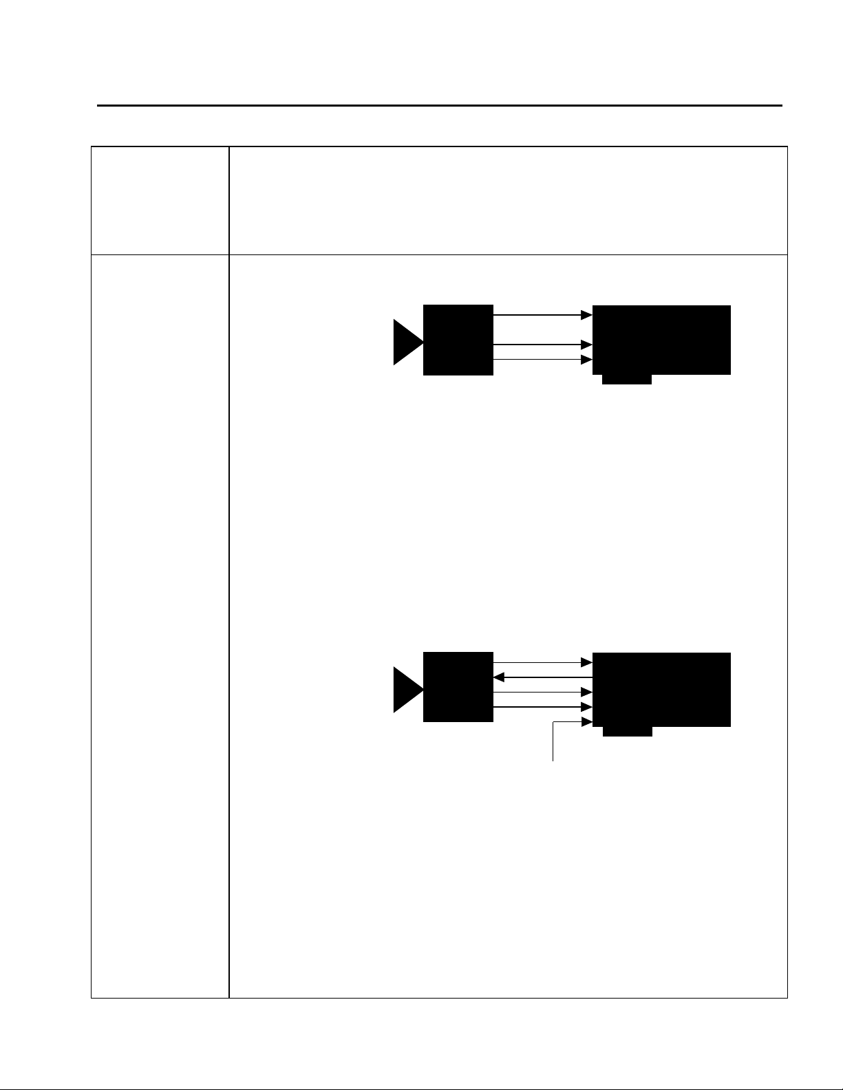
1. Continuous line scan mode
Video
iVC-
185BC
• 5000 x 1 x 8-bit
• Analog or digital video output (RS-422)
• DCF configured for 750 lines per virtual frame
• The line scan rate and the exposure time are determined by the frequency of the hsync
CLTout
RCLK
Matrox Pulsar
(with PLS-TTL-CABLE
or PULSAR/DIG/MOD)
(CLTout) signal; the exposure time is the period of the CLTout signal, which is set
using the thumb wheel on the rear of the camera
• Continuous video
• Camera sending RS-422 hsync (CLTout) and RS-422 pixel clock (RCLK @ 20MHz)
signals to Matrox Pulsar
• DCFs used: IV185L.DCF (analog video output)
IV185DL.DCF (digital video output)
2. Asynchronous line scan mode
Video
iVC-
185BC
• 5000 x 1 x 8-bit
• Analog or digital video output (RS-422)
• DCF configured for 750 lines per virtual frame
• The line scan rate and the exposure time are determined by the frequency of the
LTin
CLTout
RCLK
TTL external trigger
Matrox Pulsar
(with PLS-TTL-CABLE
or PULSAR/DIG/MOD)
external trigger signal; the exposure time is the time between external trigger signals
• Matrox Pulsar receiving TTL external trigger
• Matrox Pulsar sending asynchronous RS-422 EXPOSURE1 (LTin) signal to camera
to initiate line readout
• Camera sending RS-422 hsync (CLTout) and RS-422 pixel clock (RCLK @ 20MHz)
signals to Matrox Pulsar
• DCFs used: IV185AL.DCF (analog video output)
IV185DAL.DCF (digital video output)
Page 2
Application Note:
Interfacing non-standard cameras to Matrox Pulsar
i2S iVC185BC May 27, 1996
Camera
Interface
Details
Cabling
Requirements
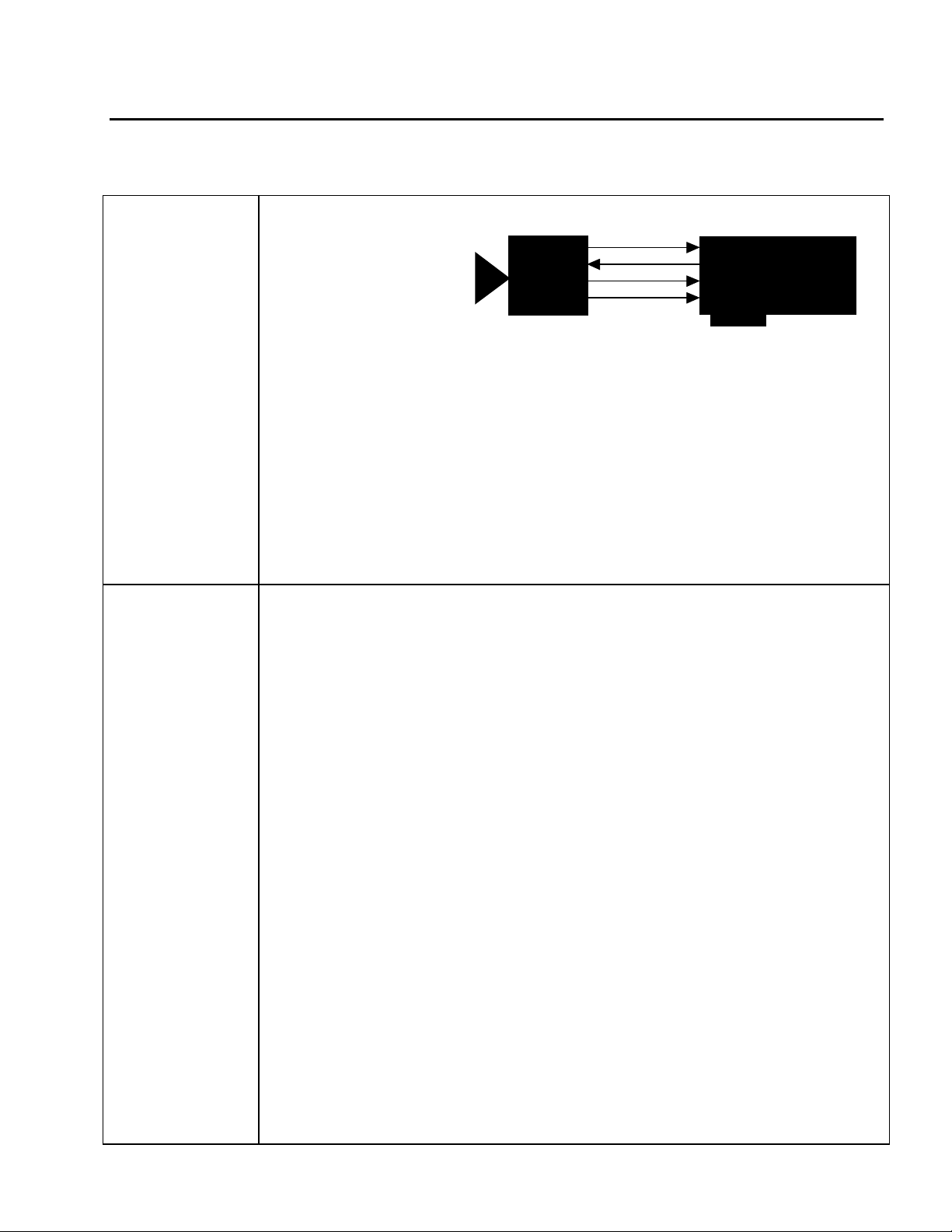
3. Periodic exposure control line scan mode
Video
iVC-
185BC
• 5000 x 1 x 8-bit
• Analog or digital video output (RS-422)
• DCF configured for 750 lines per virtual frame
• The line scan rate and the exposure time are determined by the frequency of the
LTin
CLTout
RCLK
Matrox Pulsar
(with PLS-TTL-CABLE
or PULSAR/DIG/MOD)
periodic trigger signal supplied by the Pulsar; the exposure time is the reciprocal of the
frequency of this signal
• Matrox Pulsar sending periodic RS-422 EXPOSURE1 (LTin) signal to camera to
initiate line readout
• Camera sending RS-422 hsync (CLTout) and RS-422 pixel clock (RCLK @ 20MHz)
signals to Matrox Pulsar
• DCFs used: IV185EL.DCF (analog video output)
• IV185DEL.DCF (digital video output)
1a. Continuous line scan: analog video output
• IMG-7W2-TO-1BNC cable required for video signal and PLS-TTL-CABLE required
for digital syncs and control signals in RS-422 format
• The connections between the DB-15 connector on the rear panel of the camera and a
BNC connector are as follows:
i2S iVC185BC
(DB-15 male connector) BNC connector
Pin no.Pin name
15 Video composite VIDEO OUT
7 Analog ground GROUND
• The video input BNC of the IMG-7W2-TO-1BNC cable should be connected to the
above BNC connector
• The connections between the DB-15 connector on the rear panel of the camera and the
DB-37 connector of the PLS-TTL-CABLE are as follows:
i2S iVC185BC PLS-TTL-CABLE
(DB-15 male connector) (DB-37 female connector)
Pin name Pin no. Pin name Pin no.
GROUND 2 GROUND 3
LT+ 3 ← EXPOSURE1+ 21
RCLK+ 4 → CLKIN+ 4
CLT+ 5 → HSYNC+ 16
GROUND 9 GROUND 33
LT− 10 ← EXPOSURE1− 2
RCLK− 11 → CLKIN− 22
CLT− 12 → HSYNC− 34
PUL-CID-019 2
Page 3

Application Note:
Interfacing non-standard cameras to Matrox Pulsar
i2S iVC185BC May 27, 1996
Cabling
Requirements
• NOTE: although connected, the EXPOSURE1 signal is not used in this mode
• The connections between the DB-15 connector on the rear panel of the camera and the
power supply are as follows:
i2S iVC185BC
(DB-15 male connector) POWER SUPPLY
Pin no. Pin name
1 DCin +9V < Dcin < +18V
9 GROUND GROUND
• NOTE: the following pins of the DB-15 connector on the rear panel of the camera must
be shorted together: 8 (Analog ground), 7 (Analog ground) and 2 (Ground)
1b. Continuous line scan: digital video output
• PULSAR/DIG/MOD required for digital data, syncs and control signals in RS-422
format
• The connections between the DB-25 connector on the rear panel of the camera and the
68-pin connector of the PULSAR/DIG/MOD are as follows:
i2S iVC185BC PULSAR/DIG/MOD
(DB-25 male connector) (68-pin connector)
Pin name Pin no. Pin name Pin no.
LT+ 2 ← EXPOSURE1+ 30
RCLK+ 3 → CLKIN+ 29
CLT+ 4 → HSYNC+ 26
D7+ 5 → DATA7+ 10
D6+ 6 → DATA6+ 11
D5+ 7 → DATA5+ 13
D4+ 8 → DATA4+ 14
D3+ 9 → DATA3+ 15
D2+ 10 → DATA2+ 16
D1+ 11 → DATA1+ 19
D0+ 12 → DATA0+ 20
GROUND 13 GROUND 12
GROUND 14 GROUND 46
LT− 15 ← EXPOSURE1− 64
RCLK− 16 → CLKIN− 63
CLT− 17 → HSYNC− 60
D7− 18 → DATA7− 44
D6− 19 → DATA6− 45
D5− 20 → DATA5− 47
D4− 21 → DATA4− 48
D3− 22 → DATA3− 49
D2− 23 → DATA2− 50
D1− 24 → DATA1− 53
D0− 25 → DATA0− 54
• NOTE: although connected, the EXPOSURE1 signal is not used in this mode.
PUL-CID-019 3
Page 4

Application Note:
Interfacing non-standard cameras to Matrox Pulsar
i2S iVC185BC May 27, 1996
• The connections between the DB-25 connector on the rear panel of the camera and the
power supply are as follows:
i2S iVC185BC
(DB-25 male connector) POWER SUPPLY
Pin no. Pin name
1 DCin +9V < Dcin < +18V
13 GROUND GROUND
2a. Asynchronous line scan: analog video output
• IMG-7W2-TO-5BNC cable required for video signal and TTL external trigger source;
PLS-TTL-CABLE required for digital syncs and control signals in RS-422 format
• The connections between the DB-15 connector on the rear panel of the camera and a
BNC connector are as in continuous line scan: analog video output; this BNC connector
should be connected to the video input BNC of the IMG-7W2-TO-5BNC cable
• The connections between the DB-15 connector on the rear panel of the camera and the
37-pin connector of the PLS-TTL-CABLE are as in continuous line scan: analog video
output
• The connections between the DB-15 connector on the rear panel of the camera and the
power supply are as in continuous line scan: analog video output;
• Pins 8,7 and 2 of the DB-15 connector of the camera are shorted together
• TTL external trigger source should be connected to the TTL Trigger Input of the IMG-
7W2-TO-5BNC cable
2b. Asynchronous line scan: digital video output
• IMG-7W2-TO-5BNC cable required for TTL external trigger source;
PULSAR/DIG/MOD required for digital data, syncs and control signals in RS-422
format
• The connections between the DB-25 connector on the rear panel of the camera and the
68-pin SCSI-2 connector of the PULSAR/DIG/MOD are as in continuous line scan:
digital video output
• The connections between the DB-25 connector on the rear panel of the camera and the
power supply are as in continuous line scan: digital video output
• TTL external trigger source should be connected to the TTL Trigger Input of the IMG-
7W2-TO-5BNC cable
PUL-CID-019 4
Page 5

Application Note:
Interfacing non-standard cameras to Matrox Pulsar
i2S iVC185BC May 27, 1996
Cabling
Requirements
3a. Periodic exposure control line scan: analog video output
• IMG-7W2-TO-1BNC cable required for video signal and PLS-TTL-CABLE required
for digital syncs and control signals in RS-422 format
• The connections between the DB-15 connector on the rear panel of the camera and a
BNC connector are as in continuous line scan: analog video output; this BNC connector
should be connected to the video input BNC of the IMG-7W2-TO-1BNC cable
• The connections between the DB-15 connector on the rear panel of the camera and the
37-pin connector of the PLS-TTL-CABLE are as in continuous line scan: analog video
output
• The connections between the DB-15 connector on the rear panel of the camera and the
power supply are as in continuous line scan: analog video output
• Pins 8,7 and 2 of the DB-15 connector of the camera are shorted together
3b. Periodic exposure control line scan: digital video output
• PULSAR/DIG/MOD required for digital data, syncs and control signals in RS-422
format
• The connections between the DB-25 connector on the rear panel of the camera and the
68-pin SCSI-2 connector of the PULSAR/DIG/MOD are as in continuous line scan:
digital video output
• The connections between the DB-25 connector on the rear panel of the camera and the
power supply are as in continuous line scan: digital video output
Special
Considerations
• In addition to the DCFs, PSG FPGA version 3.01 or newer is required; if this version is
not on your release of the MIL driver for Pulsar, the newest version can be found on the
BBS or at the FTP site
1. Continuous line scan (analog or digital video outputs)
• The line scan rate and the exposure time are determined by the frequency of the hsync
(CLTout) signal; the exposure time is the period of the CLTout signal, which is set using
the thumb wheel on the rear of the camera.
PUL-CID-019 5
Page 6

Application Note:
Interfacing non-standard cameras to Matrox Pulsar
i2S iVC185BC May 27, 1996
Special
Considerations
• The thumb wheel settings correspond to the following exposure times:
Position Exposure time
0
1 250µs
2 500µs
3 1ms
4 2ms
5 4ms
6 8ms
7 16ms
8 20ms
9 external mode
2. Asynchronous line scan (analog or digital video outputs)
• The thumb wheel on the rear of the camera must be set to position 9: external mode
• The line scan rate and the exposure time are determined by the frequency of the external
trigger signal; the exposure time is the time between external trigger signals
• Once it has received the external signal to trigger, the Pulsar sends the asynchronous RS-
422 EXPOSURE1 (LTin) signal to the camera to initiate line readout. The camera
returns the RS-422 hsync (CLTout) and pixel clock (RCLK) signals to the Pulsar
• The first frame to be read out will be inaccurate; the exposure time is the time between
trigger signals, therefore the first frame will correspond to the first trigger signal and the
one previous to it. The correct frame will be read out on the second trigger signal
• Trigger rate can vary between 50Hz and 3.9kHz
3. Exposure control line scan (analog or digital video outputs)
• The thumb wheel on the rear of the camera must be set to position 9: external mode
• The line scan rate and the exposure time are determined by the frequency of the periodic
trigger signal supplied by the Pulsar; the exposure time is the reciprocal of the frequency
of this signal
• Once it has received the external signal to trigger, the Pulsar sends the periodic RS-422
EXPOSURE1 (LTin) signal to the camera. The camera returns the RS-422 hsync
(CLTout) and pixel clock (RCLK) signals to the Pulsar
PUL-CID-019 6
Page 7

Application Note:
Interfacing non-standard cameras to Matrox Pulsar
i2S iVC185BC May 27, 1996
Special
Considerations
• The frequency of the periodic EXPOSURE1 signal can vary between 50Hz and 3.9kHz.
The frequency of this signal can be adjusted though the use of Intellicam: load the proper
DCF and go into Camera Spec. Editor. Move the cursor down to EXPOSURE such
that the words “periodic generated” are selected and press enter; an interface entitled
“Exposure signal information” will open. The frequency of the periodic EXPOSURE1
signal, and thus the exposure time itself, can be modified by changing the time specified
for Tlow. Under the heading of sec., select the exposure time in seconds. To complete
this operation by accepting and computing the registers etc., follow the instructions in the
Intellicam User Guide. The default setting of the exposure time is 4.55ms, which
corresponds to a frequency of 220Hz
• When the exposure time is changed, the first frame to be read out will be inaccurate; the
exposure time is the time between trigger signals, therefore the first frame will
correspond to an exposure time that is different from the desired one. The second frame
read out, and those that follow, will be correct
The DCF(s) mentioned in this application note can be found on the MIL and MIL-Lite CD, or our FTP site (ftp.matrox.com). The information furnished by
Matrox Electronics System, Ltd. is believed to be accurate and reliable. Please verify all interface connections with camera documentation or manual.
Contact your local sales representative or Matrox Sales office or Matrox Imaging Applications at 514-822-6061 for assistance.
CorporateCorporate
Headquarters:Headquarters:
Canada and U.S.A.Canada and U.S.A.
Matrox ElectronicMatrox Electronic
Systems Ltd.Systems Ltd.
1055 St.Regis Blvd.
Dorval, Quebec, Canada
H9P 2T4
Tel: (514) 685-7230
Fax: (514) 822-6273
Sales Offices:Sales Offices:
U.K.U.K.
Matrox (UK) Ltd.Matrox (UK) Ltd.
Sefton Park, Stoke Poges
Buckinghamshire
U.K. SL2 4JS
Tel: +44 (0) 1753 665500
Fax: +44 (0) 1753
665599
FranceFrance
Matrox France SARLMatrox France SARL
2, rue de la Couture,
Silic 225
94528 Rungis Cedex
Tel: (0) 1 45-60-62-00
Fax: (0) 1 45-60-62-05
GermanyGermany
Matrox GmbHMatrox GmbH
Inselkammerstr.8
D-82008
Unterhaching
Germany
Tel: 089/614 4740
Fax: 089/614 9743
Asia PacificAsia Pacific
Matrox Asia LiaisonMatrox Asia Liaison
OfficeOffice
Rm. 1901, 19/F, Workington
Tower,
78 Bonham Strand E.,
Sheung Wan, Hong Kong.
Tel: 852.2877.5387
Fax: 852.2537.9530
PUL-CID-019 7
 Loading...