

Page 1
Application Note:
Interfacing non-standard cameras to Matrox Pulsar
Phillips FTM12 February 7, 1996
Camera
Interface
Overview
Camera
Interface
Details
• 1024 x 1024 x 8-bit @ 30fps (max) or 1024 x 512 x 8-bit @ 60fps (max)
• Analog video output
• Interlaced or non-interlaced
• Internal TTL hsync and vsync signals supplied externally
• Internal or external exposure (frame integration time) control
• Accepts asynchronous TTL external trigger
• 60Hz maximum frame rate/40MHz clock rate version
• 3 modes of operation: continuous (3 submodes), trigger, control
• Modification of the integration (or exposure) time is possible in each of these 3 modes; the
frame rate is determined by the integration time (in addition to a constant frameshift
duration of 0.7ms)
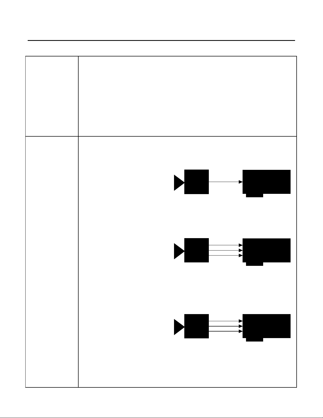
1. Continuous Mode
Submode 1:
• 1024 x 1024 x 8-bit @ 30fps (max)
• Analog (composite) video output
• Interlaced
• Continuous video
• Internal exposure control:
1.024ms to 19.328ms in increments of 1.024ms (frame rate is altered accordingly)
• DCF used: FTM12.DCF
Philips
FTM12
Video
Matrox Pulsar
(with PLS-TTL-CABLE)
Submode 2:
• 1024 x 1024 x 8-bit @ 30fps (max)
• Analog video output
• Interlaced
• Continuous video
• Internal exposure control:
Philips
FTM12
1.024ms to 19.328ms in increments of 1.024ms (frame rate is altered accordingly)
• Matrox Pulsar receiving TTL hsync (HD) and vsync (VD) signals from camera
• DCF used: FTM12S.DCF
Submode 3:
• 1024 x 512 x 8-bit @ 60fps (max)
• Analog video output
• Non-interlaced
• Continuous video
• Internal exposure control:
1.024ms to 19.328ms in increments of 1.024ms (frame rate is altered accordingly)
• Matrox Pulsar receiving TTL hsync (HD) and vsync (VD) signals from camera
• DCF used: FTM12NS.DCF
Philips
FTM12
Video
HD
VD
Video
HD
VD
Matrox Pulsar
(with PLS-TTL-CABLE)
Matrox Pulsar
(with PLS-TTL-CABLE)
Page 2
Application Note:
Interfacing non-standard cameras to Matrox Pulsar
Phillips FTM12 February 7, 1996
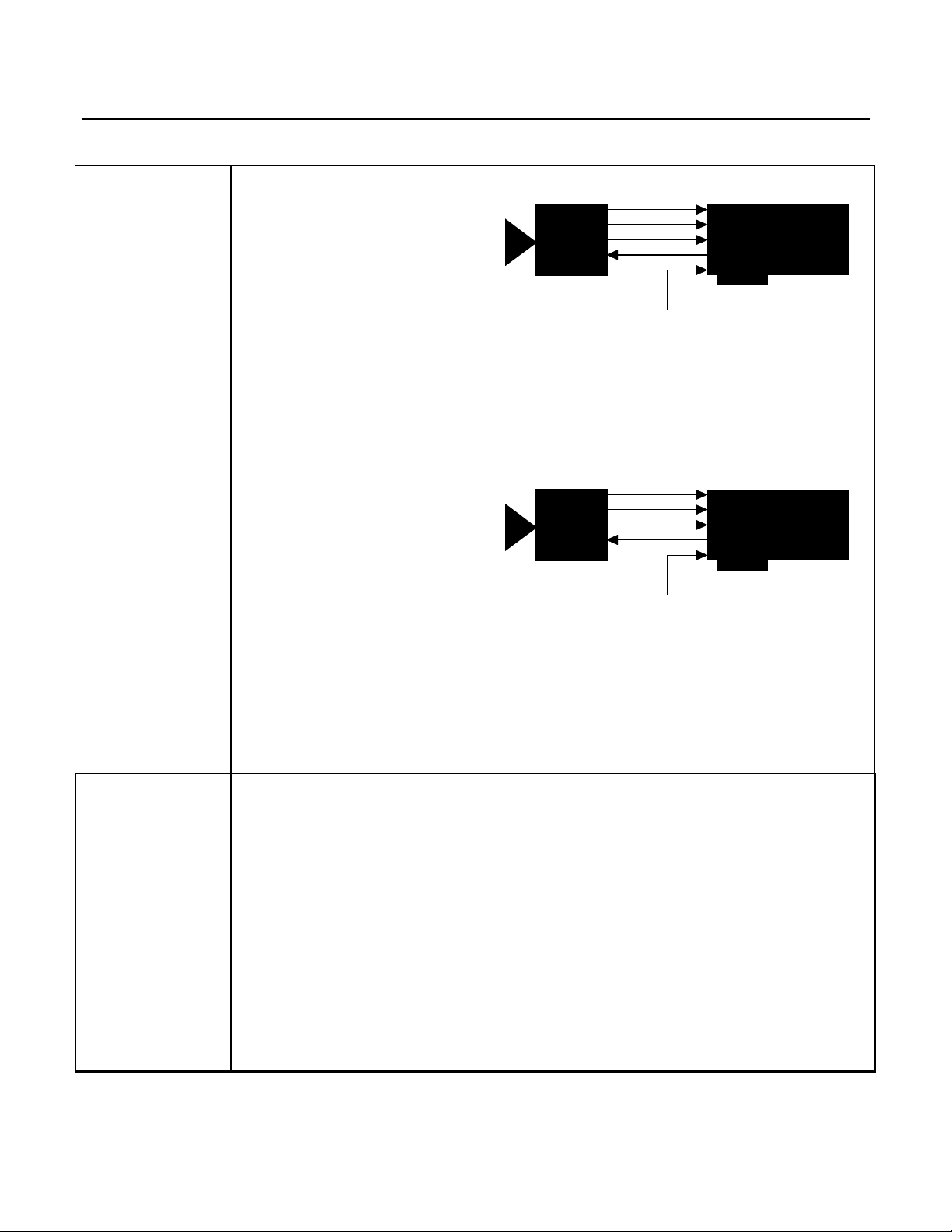
2. Trigger Mode
• 1024 x 512 x 8-bit @ 60fps (max)
• Analog video output
• Non-interlaced
• Internal exposure control:
Philips
FTM12
Video
HD
VD
Trigger
TTL external trigger
Matrox Pulsar
(with PLS-TTL-CABLE)
Range 1: 819.2µs to 25.395ms in increments of 819.2µs
Range 2: 26.214ms to 812.65ms in increments of 26.214ms
(frame rate is altered accordingly)
• Matrox Pulsar receiving TTL hsync (HD) and vsync (VD) signals from camera
• Matrox Pulsar receiving TTL external trigger
• Matrox Pulsar sends TTL exposure signal to trigger input of camera to initiate exposure
• DCF used: FTM12ANS.DCF
Video
3. Control Mode
• 1024 x 512 x 8-bit @ 60fps (max)
• Analog video output
• Non-interlaced
• External exposure control with times starting at 88.8µs (frame rate is altered accordingly)
• Matrox Pulsar receiving TTL hsync (HD) and vsync (VD) signals from camera
• Matrox Pulsar receiving TTL external trigger
• Matrox Pulsar sends TTL exposure signal to trigger input of camera to initiate exposure;
Philips
FTM12
HD
VD
Trigger
TTL external trigger
Matrox Pulsar
(with PLS-TTL-CABLE)
the exposure signal both initiates exposure and controls exposure time
• DCF used: FTM12ANE.DCF
Cabling
1. Continuous Mode
Requirements
Submode 1:
• IMG-7W2-TO-1BNC required
• Video input BNC of IMG-7W2-TO-1BNC cable should be connected to VIDEO OUT
BNC connector of camera
• Camera must be configured in interlaced mode
Submode 2:
• IMG-7W2-TO-1BNC and PLS-TTL-CABLE required
• Video input BNC of IMG-7W2-TO-1BNC cable should be connected to VIDEO OUT
BNC connector of camera
• Camera must be configured in interlaced mode
PUL-CID-006 2
Page 3

Application Note:
Interfacing non-standard cameras to Matrox Pulsar
Phillips FTM12 February 7, 1996
Cabling
Requirements
• The following connections should be made between the DB-37 connector of the
PLS-TTL-CABLE and the 25-pin sub/D connector of the camera:
PLS-TTL-CABLE PHILIPS FTM12
(DB-37 connector) (25-pin sub/D connector)
Pin name Pin no. Pin name Pin no.
TTL_HSYNC 26 ← HDB 22
TTL_EXPOSURE1 9 → TRIGR 18
TTL_VSYNC 11 ← VDB 23
• Note here that the trigger input of the camera is tied to the exposure output of the
Pulsar, though the exposure output itself is not used; this precaution prevents the
trigger input from picking up stray signals that might lead to unwanted triggering of
the camera
Submode 3:
• IMG-7W2-TO-1BNC and PLS-TTL-CABLE required
• Video input BNC of IMG-7W2-TO-1BNC cable should be connected to VIDEO OUT
BNC connector of camera
• Camera must be configured in non-interlaced mode
• The following connections should be made between the DB-37 connector of the
PLS-TTL-CABLE and the 25-pin sub/D connector of the camera:
PLS-TTL-CABLE PHILIPS FTM12
(DB-37 connector) (25-pin sub/D connector)
Pin name Pin no. Pin name Pin no.
TTL_HSYNC 26 ← HDB 22
TTL_EXPOSURE1 9 → TRIGR 18
TTL_VSYNC 11 ← FVDB 20
• Note here that the trigger input of the camera is tied to the exposure output of the
Pulsar, though the exposure output itself is not used; this precaution prevents the
trigger input from picking up stray signals that might lead to unwanted triggering of
the camera
2. Trigger Mode
• IMG-7W2-TO-5BNC cable and PLS-TTL-CABLE required
• Video input BNC of IMG-7W2-TO-5BNC cable should be connected to VIDEO OUT
BNC connector of camera
• Camera must be configured in non-interlaced mode
• The connections between the DB-37 connector of the PLS-TTL-CABLE and the 25-pin
sub/D connector of the camera are the same as those in Continuous mode: Submode 3.
The connection between the trigger input of the camera and the exposure output of the
Pulsar is now used to send asynchronous reset and exposure signals to the cameraTTL
external trigger source should be connected to the TTL Trigger Input of the IMG-7W2TO-5BNC cable
PUL-CID-006 3
Page 4

Application Note:
Interfacing non-standard cameras to Matrox Pulsar
Phillips FTM12 February 7, 1996
Cabling
Requirements
3. Control Mode
• IMG-7W2-TO-5BNC cable and PLS-TTL-CABLE required
continued
• Video input BNC of IMG-7W2-TO-5BNC cable should be connected to VIDEO OUT
BNC connector of camera
• Camera must be configured in non-interlaced mode
• The connections between the DB-37 connector of the PLS-TTL-CABLE and the 25-pin
sub/D connector of the camera are the same as those in Continuous mode: Submode 3.
The connection between the trigger input of the camera and the exposure output of the
Pulsar is now used to send asynchronous reset and exposure signals to the camera
• TTL external trigger source should be connected to the TTL Trigger Input of the IMG-
7W2-TO-5BNC cable
4. Continuous Mode:
• A table of integration time settings for the Continuous mode can be found in appendix 2 of
the User Manual for the FTM12 camera
5. Trigger Mode:
• Once it has received the external signal to trigger, the Pulsar sends a TTL exposure signal
to the camera. The camera awaits the rising edge of the signal, at which point it initiates
exposure. The exposure time is set on the camera by using the camera control software
• A table of integration time settings (for both ranges 1 and 2) for the Trigger mode can be
found in appendix 3 of the User Manual for the FTM12 camera
• An exposure pulse going high before the integration period has ended will result in a
charge reset; the integration time counter resets and starts again from zero
• Minimum duration of an exposure pulse must be 3.2µs
Special
Considerations
3. Control Mode:
• Once it has received the external signal to trigger, the Pulsar sends a TTL exposure signal
to the camera. The camera awaits the rising edge of the signal, at which point it initiates
exposure. The exposure time is set by the Pulsar; the camera will expose for as long as the
exposure signal is high
• When the exposure pulse goes down, frameshift will start. If there is an exposure pulse
before the complete storage part is read out, the rest of the image will be lost and the
sequence starts again. Using this feature it is possible to get a higher frame rate if part of
the image is not needed
PUL-CID-006 4
Page 5

Application Note:
Interfacing non-standard cameras to Matrox Pulsar
Phillips FTM12 February 7, 1996
Special
Considerations
• Exposure time can be modified using Matrox Intellicam. Consult the Matrox Intellicam
User Guide for more information
• Default exposure time is 10ms
The DCF(s) mentioned in this application note can be found on the MIL and MIL-Lite CD, or our FTP site (ftp.matrox.com). The information furnished by
Matrox Electronics System, Ltd. is believed to be accurate and reliable. Please verify all interface connections with camera documentation or manual.
Contact your local sales representative or Matrox Sales office or Matrox Imaging Applications at 514-822-6061 for assistance.
CorporateCorporate
Headquarters:Headquarters:
Canada and U.S.A.Canada and U.S.A.
Matrox ElectronicMatrox Electronic
Systems Ltd.Systems Ltd.
1055 St.Regis Blvd.
Dorval, Quebec, Canada
H9P 2T4
Tel: (514) 685-7230
Fax: (514) 822-6273
Sales Offices:Sales Offices:
U.K.U.K.
Matrox (UK) Ltd.Matrox (UK) Ltd.
Sefton Park, Stoke Poges
Buckinghamshire
U.K. SL2 4JS
Tel: +44 (0) 1753 665500
Fax: +44 (0) 1753
665599
FranceFrance
Matrox France SARLMatrox France SARL
2, rue de la Couture,
Silic 225
94528 Rungis Cedex
Tel: (0) 1 45-60-62-00
Fax: (0) 1 45-60-62-05
GermanyGermany
Matrox GmbHMatrox GmbH
Inselkammerstr.8
D-82008
Unterhaching
Germany
Tel: 089/614 4740
Fax: 089/614 9743
Asia PacificAsia Pacific
Matrox Asia LiaisonMatrox Asia Liaison
OfficeOffice
Rm. 1901, 19/F, Workington
Tower,
78 Bonham Strand E.,
Sheung Wan, Hong Kong.
Tel: 852.2877.5387
Fax: 852.2537.9530
PUL-CID-006 5
 Loading...