

Maxtor DIAMONDMAXTMPLUS6800 90683U2, DIAMONDMAXTMPLUS6800 92732U8, DIAMONDMAXTMPLUS6800 92049U6, DIAMONDMAXTMPLUS6800 91707U5, DIAMONDMAXTMPLUS6800 91366U4 User Manual
...Page 1

HARD DRIVE
P RODUCT
MANUAL
DiamondMax™Plus 6800
92732U8, 92049U6, 91707U5
91366U4, 91024U3, 90683U2
Page 2

DiamondMax™ Plus 6800
92732U8, 92049U6, 91707U5, 91366U4
91024U3 and 90683U2
Part #1418/A
All material contained herein Copyright © 1999 Maxtor Corporation.
DiamondMax™, DiamondMax™ 6800, DiamondMax™ Plus 6800,
DiamondMax™ Plus 5120 and MaxFax™ are trademarks of Maxtor
Corporation. No Quibble® Service is a registered trademark of Maxtor
Corporation. Other brands or products are trademarks or registered
trademarks of their respective holders. Contents and specifications
subject to change without notice. All rights reserved.
Corporate Headquarters
510 Cottonwood Drive
Milpitas, California 95035
Tel: 408-432-1700
Fax: 408-432-4510
Research and Development
Engineering Center
2190 Miller Drive
Longmont, Colorado 80501
Tel: 303-651-6000
Fax: 303-678-2165
Page 3

Revisions Manual No. 1418
VER.ONCENOITCESNOITPIRCSED ETAD
A51697llA.esaelerlaitinI 99/32/70
Page 4

Before Y ou Begin
Thank you for your interest in the Maxtor DiamondMax™ Plus 6800 AT hard disk drives. This manual provides
technical information for OEM engineers and systems integrators regarding the installation and use of DiamondMax
hard drives.
the Maxtor Customer Service Center at 800-2MAXTOR or 408-922-2085.
Before unpacking the hard drive, please review Sections 1 through 4.
Drive repair should be performed only at an authorized repair center. For repair information, contact
CAUTION
Maxtor DiamondMax Plus 6800 hard drives are precision products. Failure to
follow these precautions and guidelines outlined here may lead to
product failure, damage and invalidation of all warranties.
1
2
3
4
5
BEFORE unpacking or handling a drive, take all proper electro-static discharge (ESD)
precautions, including personnel and equipment grounding. Stand-alone drives are sensitive to
ESD damage.
BEFORE removing drives from their packing material, allow them to reach room
temperature.
During handling, NEVER drop, jar, or bump a drive.
Once a drive is removed from the Maxtor shipping container, IMMEDIATELY secure the drive
through its mounting holes within a chassis. Otherwise, store the drive on a padded, grounded,
antistatic surface.
NEVER switch DC power onto the drive by plugging an electrically live DC source cable into
the drive's connector. NEVER connect a live bus to the drive's interface connector.
Please do not remove or cover up Maxtor factory-installed drive labels.
They contain information required should the drive ever need repair.
Page 5

DIAMONDMAX PLUS 6800 PRODUCT MANUAL
Contents
Section 1 — Introduction
Maxtor Corporation 1 - 1
Products 1 - 1
Support 1 - 1
Manual Organization 1 - 1
Abbreviations 1 - 1
Conventions 1 - 2
Key Words 1 - 2
Numbering 1 - 2
Signal Conventions 1 - 2
Section 2 — Product Description
The DiamondMax™ Plus 6800
Product Features 2 - 2
Functional/Interface 2 - 2
Zone Density Recording 2 - 2
Read/Write Multiple Mode 2 - 2
UltraDMA - Mode 2 2 - 2
Multi-word DMA (EISA Type B) - Mode 2 2 - 2
Sector Address Translation 2 - 2
Logical Block Addressing 2 - 3
Defect Management Zone 2 - 3
On-the-Fly Hardware Error Correction Code (ECC) 2 - 3
Software ECC Correction 2 - 3
Automatic Head Park and Lock Operation 2 - 3
Cache Management 2 - 4
Buffer Segmentation 2 - 4
Read-Ahead Mode 2 - 4
Automatic Write Reallocation (AWR) 2 - 4
Write Cache Stacking 2 - 4
Major HDA Components 2 - 5
Drive Mechanism 2 - 5
Rotary Actuator 2 - 5
Read/Write Electronics 2 - 5
Read/Write Heads and Media 2 - 5
Air Filtration System 2 - 5
Microprocessor 2 - 5
Subsystem Configuration 2 - 6
Dual Drive Support 2 - 6
Cable Select Option 2 - 6
Jumper Location/Configuration 2 - 6
4092 Cylinder Limitation 2 - 6
i
Page 6

DIAMONDMAX PLUS 6800 PRODUCT MANUAL
Section 3 — Product Specifications
Models and Capacities 3 - 1
Drive Configuration 3 - 1
Performance Specifications 3 - 1
Physical Dimensions 3 - 2
Power Requirements 3 - 3
Power Mode Definitions 3 - 3
Spin-up 3 - 3
Seek 3 - 3
Read/Write 3 - 3
Idle 3 - 3
Standby 3 - 3
Sleep 3 - 3
EPA Energy Star Compliance 3 - 3
Environmental Limits 3 - 3
Shock and Vibration 3 - 4
Reliability Specifications 3 - 4
Annual Return Rate 3 - 4
Quality Acceptance Rate 3 - 4
Start/Stop Cycles 3 - 4
Data Reliability 3 - 4
Component Design Life 3 - 4
EMC/EMI 3 - 5
EMC Compliance 3 - 5
Canadian Emissions Statement 3 - 5
Safety Regulatory Compliance 3 - 5
Section 4 — Handling and Installation
Pre-formatted Drive 4 - 1
Important Notice 4 - 1
Hard Drive Handling Precautions 4 - 1
Electro-Static Discharge (ESD) 4 - 1
Unpacking and Inspection 4 - 2
Repacking 4 - 3
Physical Installation 4 - 3
Before You Begin 4 - 4
Please Read 4 - 4
Handling Precautions 4 - 4
Tools for Installation 4 - 4
Drive Identification Information 4 - 4
Capacity Barriers 4 - 4
Protecting Your Existing Data 4 - 4
General Requirements 4 - 5
System Hardware Requirements 4 - 5
BIOS Requirements 4 - 5
ii
Page 7

DIAMONDMAX PLUS 6800 PRODUCT MANUAL
Ultra Direct Memory Access (UDMA) 4 - 5
OS Requirements for Large Capacity Hard Drives 4 - 5
Hard Drive Identification 4 - 6
Identifying IDE Devices on the Interface 4 - 6
Jumper Settings 4 - 6
Systems Using Cable Select 4 - 6
Relationship to Other IDE Devices 4 - 6
Mounting Drive in System 4 - 7
Attaching Interface and Power Cables 4 - 7
Attaching System Cables 4 - 7
System Setup 4 - 8
Setting the BIOS (CMOS) 4 - 8
BIOS (CMOS) Parameters 4 - 8
Hard Drive Preparation 4 - 10
System Hangs During Boot 4 - 12
Section 5 — AT Interface Description
Interface Connector 5 - 1
Pin Description Summary 5 - 1
Pin Description Table 5 - 2
PIO Timing 5 - 3
DMA Timing 5 - 4
Ultra DMA Timing Parameters 5 - 5
Section 6 — Host Software Interface
Task File Registers 6 - 1
Data Register 6 - 1
Error Register 6 - 1
Features Register 6 - 1
Sector Count Register 6 - 2
Sector Number Register 6 - 2
Cylinder Number Registers 6 - 2
Device/Head Register 6 - 2
Status Register 6 - 2
Command Register 6 - 3
Read Commands 6 - 3
Write Commands 6 - 3
Mode Set/Check Commands 6 - 3
Power Mode Commands 6 - 3
Initialization Commands 6 - 3
Seek, Format, and Diagnostic Commands 6 - 3
S.M.A.R.T. Commands 6 - 3
Summary 6 - 4
Control Diagnostic Registers 6 - 5
Alternate Status Register 6 - 5
iii
Page 8

DIAMONDMAX PLUS 6800 PRODUCT MANUAL
Device Control Register 6 - 5
Digital Input Register 6 - 5
Reset and Interrupt Handling 6 - 6
Section 7 — Interface Commands
Command Summary 7 - 1
Read Commands 7 - 2
Read Sector(s) 7 - 2
Read Verify Sector(s) 7 - 2
Read Sector Buffer 7 - 2
Read DMA 7 - 3
Read Multiple 7 - 3
Set Multiple 7 - 3
Write Commands 7 - 4
Write Sector(s) 7 - 4
Write Verify Sector(s) 7 - 4
Write Sector Buffer 7 - 4
Write DMA 7 - 5
Write Multiple 7 - 5
Ultra DMA 7 - 5
Set Feature Commands 7 - 5
Set Features Mode 7 - 5
Power Mode Commands 7 - 7
Standby Immediate 7 - 7
Idle Immediate 7 - 7
Standby 7 - 7
Idle 7 - 7
Check Power Mode 7 - 7
Set Sleep Mode 7 - 7
Default Power-on Condition 7 - 7
Initialization Commands 7 - 9
Identify Drive 7 - 9
Initialize Drive Parameters 7 - 12
Seek, Format, and Diagnostic Commands 7 - 13
S.M.A.R.T. Command Set 7 - 14
Section 8 — Service and Support
Service Policy 8 - 1
No Quibble Service 8 - 1
Support 8 - 1
Glossary
Glossary GL - 1
iv
Page 9

DIAMONDMAX PLUS 6800 PRODUCT MANUAL
Figures
Figure Title Page
2 - 1 PCBA Jumper Location and Configuration 2 - 6
3 - 1 Outline and Mounting Dimensions 3 - 2
4 - 1 Multi-pack Shipping Container 4 - 2
4 - 2 Single-pack Shipping Container (Option A) 4 - 3
4 - 3 Single-pack Shipping Container (Option B) 4 - 3
4 - 4 Master, Slave and Cable Select Settings 4 - 5
4 - 5 5.25-inch Mounting Brackets and Rails 4 - 6
4 - 6 IDE Interface and Power Cabling Detail 4 - 7
4 - 7 Master, Slave and Cable Select Settings 4 - 10
5 - 1 Data Connector 5 - 1
5 - 2 PIO Data Transfer to/from Device 5 - 3
5 - 3 Multi-word DMA Data Transfer 5 - 4
5 - 4 Initiating an Ultra DMA Data In Burst 5 - 5
5 - 5 Sustained Ultra DMA Data In Burst 5 - 6
5 - 6 Host Pausing an Ultra DMA Data In Burst 5 - 6
5 - 7 Device Terminating an Ultra DMA Data In Burst 5 - 7
5 - 8 Host Terminating an Ultra DMA Data In Burst 5 - 7
5 - 9 Initiating an Ultra DMA Data Out Burst 5 - 8
5 - 10 Sustained Ultra DMA Data Out Burst 5 - 8
5 - 11 Device Pausing an Ultra DMA Data Out Burst 5 - 9
5 - 12 Host Terminating an Ultra DMA Data Out Burst 5 - 9
5 - 13 Device Terminating an Ultra DMA Data Out Burst 5 - 10
v
Page 10

DIAMONDMAX PLUS 5120 – INTRODUCTION
SECTION 1
Introduction
Maxtor Corporation
Maxtor Corporation has been providing high-quality computer storage products since 1982. Along the way,
we’ve seen many changes in data storage needs. Not long ago, only a handful of specific users needed more than
a couple hundred megabytes of storage. Today, downloading from the Internet and CD-ROMs, multimedia,
networking and advanced office applications are driving storage needs even higher. Even home PC applications
need capacities measured in gigabytes, not megabytes.
Products
Maxtor’s products meet those demanding storage capacity requirements with room to spare. They feature
proven compatibility and reliability. While DiamondMax™ Plus 6800 is the latest addition to our family of
high performance 7,200 RPM desktop hard drives, DiamondMax™ 6800 series hard drives deliver industryleading capacity, performance and value for many PC applications.
Support
No matter which capacity, all Maxtor hard drives are supported by our commitment to total customer
satisfaction and our No Quibble
(http://www.maxtor.com) – puts you in touch with either technical support or customer service. We’ll
provide you the information you need quickly, accurately and in the form you prefer – a fax, a downloaded
file or a conversation with a representative.
®
Service guarantee. One call – or a visit to our home page on the Internet
Manual Organization
This hard disk drive reference manual is organized in the following method:
❏ Section 1 – Introduction
❏ Section 2 – Description
❏ Section 3 – Specifications
❏ Section 4 – Installation
❏ Section 5 – AT Interface
❏ Section 6 – Host Software Interface
❏ Section 7 – Interface Commands
❏ Section 8 – Service and Support
❏ Appendix – Glossary
Abbreviations
VRBBANOITPIRCSEDVRBBANOITPIRCSED
ATAtnemhcattaTABMetybagem
ipbhcnirepstibces/stibMdnocesrepstibagem
SHCrotces-daeh-rednilycces/BMdnocesrepsetybagem
bdslebicedzHMztrehagem
ABddethgiewA,slebicedsmdnocesillim
AMDsseccayromemtceridBSMtibtnacifingistsom
CCEedocnoitcerrocrorreVmstlovillim
icfhcnirepsegnahcxulfsnsdnocesonan
GnoitareleccaOIPtuptuo/tupnidemmargorp
BGetybagigMPRetunimrepsnoitulover
zHztrehipthcnirepskcart
BKetybolikAMDUsseccayromemtceridartlu
ABL)gni(sserddakcolblacigolcesµdnocesorcim
BSLtibtnacifingistsaelVstlov
AmserepmaillimWsttaw
1 – 1
Page 11

DIAMONDMAX PLUS 5120 – INTRODUCTION
Conventions
If there is a conflict between text and tables, the table shall be accepted as being correct.
Key Words
The names of abbreviations, commands, fields and acronyms used as signal names are in all uppercase type
(e.g., IDENTIFY DRIVE). Fields containing only one bit are usually referred to as the “name” bit instead of
the “name” field.
Names of drive registers begin with a capital letter (e.g., Cylinder High register).
Numbering
Numbers that are not followed by a lowercase “b” or “h” are decimal values. Numbers that are followed by
a lowercase “b” (e.g., 01b) are binary values. Numbers that are followed by a lowercase “h” (e.g., 3Ah) are
hexadecimal values.
Signal Conventions
Signal names are shown in all uppercase type.
All signals are either high active or low active signals. A dash character (-) at the end of a signal name
indicates that the signal is low active. A low active signal is true when it is below ViL and is false when it is
above ViH. A signal without a dash at the end indicates that the signal is high active. A high active signal is
true when it is above ViH and is false when it is below ViL.
When a signal is asserted, it means the signal is driven by an active circuit to its true state.
When a signal is negated, it means the signal is driven by an active circuit to its false state.
When a signal is released, it means the signal is not actively driven to any state. Some signals have bias
circuitry that pull the signal to either a true or false state when no signal driver is actively asserting or negating
the signal. These instances are noted under the description of the signal.
1 – 2
Page 12

PRODUCT DESCRIPTION
SECTION 2
Product Description
Maxtor DiamondMax™ Plus 6800 AT disk drives are 1-inch high, 3.5-inch diameter random access storage
devices which incorporate an on-board ATA-5/Ultra DMA 66 controller. High capacity is achieved by a
balanced combination of high areal recording density and the latest data encoding and servo techniques.
Maxtor's latest advancements in electronic packaging and integration methods have lowered the drive's power
consumption and increased its reliability. Advanced giant magneto-resistive read/write heads and a state-of-the-art
head/disk assembly - using an integrated motor/spindle design - allow up to four disks in a 3.5-inch package.
Exceptionally high data transfer rates, 7,200 RPM spin speed and < 9.0 ms access times make these performance
series disk drives especially well-suited to high-end desktop and server applications.
DiamondMax Plus 6800 Key Features
ANSI ATA-5 compliant PIO Mode 4 interface (Enhanced IDE)
Supports Ultra DMA Mode 4 for up to 66.7 MB/sec data transfers
2 MB buffer with multi-adaptive cache manager
7,200 RPM spin speed
< 9.0 ms seek time
Zone density and I.D.-less recording
Outstanding shock resistance at 250 Gs
High durability with 50K constant start/stop cycles
Advanced multi-burst on-the-fly Error Correction Code (ECC)
Extended data integrity with ECC protected data and fault tolerant servo synchronization fields
Supports EPA Energy Star Standards (Green PC Friendly) with ATA powering savings commands
Auto park and lock actuator mechanism
Low power consumption
S.M.A.R.T. Capability
Note: Maxtor defines one megabyte as 106 or one million bytes and one gigabyte as 109 or one billion bytes.
2 – 1
Page 13

PRODUCT DESCRIPTION
Product Features
Functional / Interface
Maxtor DiamondMax™ Plus 6800 hard drives contain all necessary mechanical and electronic parts to interpret
control signals and commands from an AT-compatible host computer. See Section 3 Product Specifications, for
complete drive specifications.
Zone Density Recording
The disk capacity is increased with bit density management – common with Zone Density Recording. Each
disk surface is divided into 16 circumferential zones. All tracks within a given zone contain a constant
number of data sectors. The number of data sectors per track varies in different zones; the outermost zone
contains the largest number of data sectors and the innermost contains the fewest.
Read/Write Multiple Mode
This mode is implemented per ANSI ATA/ATAPI-5 specification. Read/Write Multiple allows the host to
transfer a set number of sectors without an interrupt request between them, reducing transfer process
overhead and improving host performance.
UltraDMA - Mode 4
Maxtor DiamondMax Plus 6800 hard drives fully comply with the new ANSI Ultra DMA protocol, which
greatly improves overall AT interface performance by significantly improving burst and sustained data
throughput.
Multi-word DMA (EISA Type B) - Mode 2
Supports multi-word Direct Memory Access (DMA) EISA Type B mode transfers.
Sector Address Translation
All DiamondMax Plus 6800 drives feature a universal translate mode. In an AT/EISA-class system, the drive
may be configured to any specified combination of cylinders, heads and sectors (within the range of the
drive's formatted capacity). DiamondMax Plus 6800 drives power-up in a translate mode:
LEDOMLYCDHTPSenoZLmocPWABLXAMYTICAPAC
8U23729649,256136)*()*(865,963,35BM523,72
6U94029907,936136)*()*(276,620,04BM394,02
5U70719190,336136)*()*(827,533,33BM870,71
4U66319374,626136)*()*(487,486,62BM266,31
3U42019458,916136)*()*(238,210,02BM642,01
2U38609632,316136)*()*(888,143,31BM138,6
(*) The fields LZone (Landing Zone) and WPcom (Write Pre-comp) are not used by the Maxtor hard drive
and the values may be either 0 or the values set by the BIOS. All capacities listed in the above table are based
on 106 or one million bytes.
2 – 2
Page 14

PRODUCT DESCRIPTION
Logical Block Addressing
The Logical Block Address (LBA) mode can only be utilized in systems that support this form of translation.
The cylinder, head and sector geometry of the drive, as presented to the host, differs from the actual physical
geometry. The host AT computer may access a drive of set parameters: number of cylinders, heads and
sectors per track, plus cylinder, head and sector addresses. However, the drive can’t use these host parameters
directly because of zoned recording techniques. The drive translates the host parameters to a set of logical
internal addresses for data access.
The host drive geometry parameters are mapped into an LBA based on this formula:
LBA = (HSCA - 1) + HHDA x HSPT + HNHD x HSPT x HCYA (1)
where HSCA = Host Sector Address, HHDA = Host Head Address
= (HSCA - 1) + HSPT x (HHDA + HNHD x HCYA) (2)
HCYA = Host Cylinder Address, HNHD = Host Number of Heads
HSPT = Host Sectors per Track
The LBA is checked for violating the drive capacity. If it does not, the LBA is converted to physical drive
cylinder, head and sector values. The physical address is then used to access or store the data on the disk and
for other drive related operations.
Defect Management Zone (DMZ)
Each drive model has a fixed number of spare sectors per drive, all of which are located at the end of the
drive. Upon detection of a bad sector that has been reassigned, the next sequential sector is used.
For example, if sector 3 is flagged, data that would have been stored there is “pushed down” and recorded
in sector 4. Sector 4 then effectively becomes sector 3, as sequential sectors are “pushed down” across the
entire drive. The first spare sector makes up for the loss of sector 3, and so maintains the sequential order of
data. This push down method assures maximum performance.
On-the-Fly Hardware Error Correction Code (ECC)
5 symbols, single burst, guaranteed
Software ECC Correction
22 symbols, single burst, guaranteed
Automatic Park and Lock Operation
Immediately following power down, dynamic braking of the spinning disks delays momentarily allowing the
read/write heads to move to an inner mechanical stop. A small fixed magnet holds the rotary actuator in
place as the disk spins down. The rotary actuator is released only when power is again applied.
2 – 3
Page 15

PRODUCT DESCRIPTION
Cache Management
Buffer Segmentation
The data buffer is organized into two segments: the data buffer and the micro controller scratch pad.
The data buffer is dynamically allocated for read and write data depending on the commands received.
A variable number of read and write buffers may exist at the same time.
Read-Ahead Mode
Normally, this mode is active. Following a read request, disk read-ahead begins on the first sector and
continues sequentially until the allocated buffer is full. If a read request is received during the read-ahead
operation, the buffer is examined to determine if the request is in the cache. If a cache hit occurs, readahead mode continues without interruption and the host transfer begins immediately.
Automatic Write Reallocation (AWR)
This feature is part of the write cache and reduces the risk of data loss during deferred write operations. If a
disk error occurs during the disk write process, the disk task stops and the suspect sector is reallocated to a
pool of alternate sectors located at the end of the drive. Following reallocation, the disk write task continues
until it is complete.
Write Cache Stacking
Normally, this mode is active. Write cache mode accepts the host write data into the buffer until the buffer
is full or the host transfer is complete. A command complete interrupt is generated at the end of the transfer.
A disk write task begins to store the host data to disk. Host write commands continue to be accepted and
data transferred to the buffer until either the write command stack is full or the data buffer is full. The drive
may reorder write commands to optimize drive throughput.
2 – 4
Page 16

PRODUCT DESCRIPTION
Major HDA Components
Drive Mechanism
A brush-less DC direct drive motor rotates the spindle at 7,200 RPM (±0.1%). The dynamically balanced
motor/spindle assembly ensures minimal mechanical run-out to the disks. A dynamic brake provides a fast
stop to the spindle motor upon power removal. The speed tolerance includes motor performance and motor
circuit tolerances.
Rotary Actuator
All DiamondMax™ Plus 6800 drives employ a rotary voice coil actuator which consists of a moving coil, an
actuator arm assembly and stationary magnets. The actuator moves on a low-mass, low-friction center shaft.
The low friction contributes to fast access times and low power consumption.
Read/Write Electronics
An integrated circuit mounted within the sealed head disk assembly (near the read/write heads) provides up
to eight head selection (depending on the model), read pre-amplification and write drive circuitry.
Read/Write Heads and Media
Low mass, low force giant magneto-resistive read/write heads record data on 3.5-inch diameter disks. Maxtor
uses a sputtered thin film medium on all disks for DiamondMax Plus 6800 drives.
Air Filtration System
All DiamondMax Plus 6800 drives are assembled in a Class 100 controlled environment. Over the life of the
drive, a 0.1 micron filter and breather filter located within the sealed head disk assembly (HDA) maintain a
clean environment to the heads and disks. DiamondMax Plus 6800 drives are designed to operate in a typical
office environment with minimum environmental control.
Microprocessor
The microprocessor controls the following functions for the drive electronics:
Command execution
Cache management
Data correction and error recovery
Diagnostic execution
Data sequencing
Head positioning (including error recovery)
Host interface
Index detection
Spin speed control
Seeks
Servo
S.M.A.R.T.
2 – 5
Page 17
PRODUCT DESCRIPTION
Subsystem Configuration
Dual Drive Support
Two drives may be accessed via a common interface cable, using the same range of I/O addresses. The drives
are jumpered as device 0 or 1 (Master/Slave), and are selected by the drive select bit in the
Device/Head register of the task file.
All Task File registers are written in parallel to both drives. The interface processor on each drive decides
whether a command written to it should be executed; this depends on the type of command and which
drive is selected. Only the drive selected executes the command and activates the data bus in response to
host I/O reads; the drive not selected remains inactive.
A master/slave relationship exists between the two drives: device 0 is the master and device 1 the slave.
When J50 is closed (factory default, figure 2-1), the drive assumes the role of master; when open, the drive
acts as a slave. In single drive configurations, J50 must be closed.
Cable Select Option
CSEL (cable select) is an optional feature per ANSI ATA specification. Drives configured in a multiple drive
system are identified by CSEL’s value:
– If CSEL is grounded, then the drive address is 0.
– If CSEL is open, then the drive address is 1.
Jumper Location/Configuration
Darkened jumper pins indicate factory-installed (default) shunts.
Figure 2-1
PCBA Jumper Location and Configuration
evalS/retsaM
tceleSelbaC
*delbasiD
delbanE
*delbasiD
delbanE
devreseRyrotcaFO
devreseRyrotcaF O
NOITARUGIFNOCREPMUJ05J84J64J44J24J
*metsysevirdelgnisnievirdylnO
metsysevirdlaudnievirdevalS
noitatimiLrednilyC2904
desolC=CtluafeD=*yeK
C
*metsysevirdlaudnievirdretsaM
C
O
O
C
O
C
)dellatsnirepmuj(
nepO=O
)dellatsnirepmujon(
4092 Cylinder Limitation
On some older BIOS', primarily those that auto-configure the disk drive, a hang may occur when the drive
cylinder value exceeds 4096. The 4092 Cylinder Limitation jumper reduces the capacity in the Identify Drive to
4092 allowing large capacity drives to work with older BIOS'. A software driver is required to access the full
capacity of the drive.
2 – 6
Page 18
Product Specifications
Models and Capacities
LEDOM
yticapaCdettamroF
)edoMABLBM(
Drive Configuration
LEDOM8U237296U940295U707194U663193U420192U38609
ecafretnI/rellortnoCdetargetnI AMDartlU/5-ATA
dohteMgnidocnE 71/61LLR4RPE
evaelretnI1:1
metsySovreS deddebmE
epyT/eziSreffuB MARDSBM2
ecafruSrepsenoZataD61
sdaeH/secafruSataD865432
sksiDforebmuN 43322 1
ytisneDlaerA079,4ni/bM
ecafruSrepskcarT )srednilyC( 17, 945
ytisneDkcarT003,71ipt
ytisneDgnidroceR092-291ipbk
ytisneDxulF icfk603-042
kcolB/rotceSrepsetyB215
kcarTrepsrotceS-662426
evirDrepsrotceS
8U237296U940295U707194U663193U420192U38609
523,72394,02870,71266,31642,01138,6
6
01saetybagemenosenifedrotxaM
865,963,35276,620,04827,533,33487,486,62238,210,02888,143,31
PRODUCT SPECIFICATIONS
SECTION 3
9
01saetybagigenodnasetybnoillimenoro
2
.setybnoillibenoro
Performance Specifications
LEDOM8U237296U940295U707194U663193U420192U38609
semiTkeeS )lacipyt(
kcarT-ot-kcarT
egarevA
mumixaM sm02<
ycnetaLegarevA4.81sm
deepSlanoitatoR )%1.0±( 7,2 MPR00
daehrevOrellortnoC sm3.0<
etaRrefsnarTataD
(
artlU
ecafretnImorf/oT
edoM-AMD
4
)
ecafretnImorf/oT
aideMmorf/oT ces/BM7.33otpu
emiTtratS )ydaeRevirDot0(
)2edoM-AMDdrow-itluM/4OIP(
sm0.1
sm0.9<
ces/BM7.66otpu
ces/BM7.61otpu
0.11
lacipytces
3 – 1
Page 19

PRODUCT SPECIFICATIONS
Physical Dimensions
RETEMARAPDRADNATSCIRTEM
thgieHsehcni20.1sretemillim9.52
htgneLsehcni87.5sretemillim6.641
htdiWsehcni00.4sretemillim1.201
thgieWsdnuop3.1smargolik95.0
1.028 max
[25.9 mm]
6 x 6-32
UNC Tap
4 x 6-32
UNC Tap
4.000 ± .01
[101.6 mm]
5.787 max
[146.6 mm]
1.75 ± .02
1.638 ± .005
[41.61 mm]
1.122 ± .02
[28.4 mm]
1.625 ± .02
.25 ± .01
4.00 ± .01
[102.1 mm]
3.75 ± .01
[95.25 mm]
3 – 2
Figure 3 - 1
Outline and Mounting Dimensions
Page 20

Power Requirements
EDOM%01±V21%8±V5REWOP
pu-nipS )kaep( Am0092Am004
keeS )gva( Am029Am074W4.31
etirW/daeR )gva( Am004Am005W8<
eldI )gva( Am054Am063W2.7
ybdnatS )gva( Am02Am02W9.0
peelS )gva( Am02Am02W9.0
Power Mode Definitions
Spin-up
The drive is spinning up following initial application of power and has not yet reached full speed.
Seek
A random access operation by the disk drive.
Read/Write
Data is being read from or written to the drive.
PRODUCT SPECIFICATIONS
Idle
The drive is spinning, the actuator is parked and powered off and all other circuitry is powered on.
The drive is capable of responding to read commands within 40 ms.
Standby
The spin motor is not spinning. The drive will leave this mode upon receipt of a command that requires
disk access. The time-out value for this mode is programmable. The buffer is active to accept write data.
Sleep
This is the lowest power state – with the interface set to inactive. A software or hardware reset is required
to return the drive to the Standby state.
EPA Energy Star Compliance
Maxtor Corporation supports the goals of the U.S. Environmental Protection Agency’s Energy Star program
to reduce the electrical power consumption of computer equipment.
Environmental Limits
RETEMARAPGNITAREPOEGAROTS/GNITAREPO-NON
erutarepmeTC°55otC°5)C°04-(erutarepmetwol
.snoitidnocdecudni-toh;yrogetaccitamilc
tneidarGlamrehT (ruohrepC°52 )mumixam
ytidimuHevitaleR %59ot%5 gnisnednoc-non( )
bluBteW 72°C )mumixam(
edutitlAteef000,01ot002-teef000,04ot002-
esioNcitsuocA )edomeldI( rewopdnuosegarevaleb3.3
)enohporcim01,9777OSIrep(
,3.105dohtem,E018-DTS-LIMrep)C°17(erutarepmethgih
3 – 3
Page 21

PRODUCT SPECIFICATIONS
Shock and Vibration
RETEMARAPGNITAREPOGNITAREPO-NON
kcohSlacinahceMsrorreon,sm0.2,sG03 egamadon,sm0.2,sG052
kcohSlanoitatoR egamadon,sm0.1-5.0,ces/daR000,81
noitarbiVmodnaRG400.0tazH54-01
noitarbiVeniStpewS
Reliability Specifications
Annual Return Rate
< 1.0% Annual Return Rate (ARR) indicates the average against products
Quality Acceptance Rate
< 500 DPPM The quality acceptance rate indicates the percentage of Maxtor
2
zH/
2
G800.0tazH26-84
zH/
2
zH/
G400.0tazH003-56
2
G6000.0tazH005-103
srorreon
zH/
edutilpmaelbuodsehcni940.0
)kaep-0(edutilpmakaepG0.1
egamadon,smrG51.2tazH000,2-01
shipped. ARR includes all reasons for returns (failures, handling
damage, NDF), but does not include inventory credit returns.
products successfully installed by our customers, and/or the number
of defective parts per million (DPPM) encountered during the entire
installation process.
Start/Stop Cycles
50,000 (minimum) This indicates the minimum cycles for reliable start/stop function at a
≥ 60% confidence level.
Data Reliability
14
< 1 per 10
bits read Data errors (non-recoverable). Average data error rate allowed with all
error recovery features activated.
Component Design Life
5 years (minimum) Component design life is defined as a.) the time period before
identified wear-out mechanisms impact the failure rate, or b.) the time
period up to the wear-out point when useful component life expires.
3 – 4
Page 22

PRODUCT SPECIFICATIONS
EMC/EMI
Radiated Electromagnetic Field Emissions - EMC Compliance
The hard disk drive mechanism is designed as a subassembly for installation into a suitable enclosure and is
therefore not subject to Subpart J of Part 15 of FCC Rules (47CFR15) or the Canadian Department of
Communications Radio Interference Regulations. Although not required, the disk mechanism has been
tested within a suitable end-use product and found to comply with Class B limits of the FCC Rules and
Regulations of the Canadian Department of Communications.
The CE Marking indicates conformity with the European Union Low Voltage Directive (73/23/EEC) when
the disk mechanism is installed in a typical personal computer. Maxtor recommends that testing and analysis
for EMC compliance be performed with the disk mechanism installed within the user's end-use application.
Canadian Emissions Statement
This digital apparatus does not exceed the Class B limits for radio noise emissions from digital apparatus as set
out in the radio interference regulations of the Canadian department of communications.
Le present appareil numerique n'emet pas de bruit radioelectriques depassant les limites applicables aux
appareils numeriques de Class B prescrites dans le reglement sur le brouillage radioelectrique edicte par le
ministere des communications du Canada.
Safety Regulatory Compliance
All Maxtor hard drives comply with relevant product safety standards such as CE, CUL, TUV and UL rules and
regulations. As delivered, Maxtor hard drives are designed for system integration before they are used.
3 – 5
Page 23

SECTION 4
Handling and Installation
Pre-formatted Drive
This Maxtor hard drive has been formatted at the factory. Do not use a low-level formatting program.
Important Notice
There are a number of system BIOS’s currently in use which do not support hard drives with more than 4095
cylinders (2.1 gigabytes). This section contains information describing the conditions which may identify this
limitation. In order to obtain the full capacity of your Maxtor drive, you will need to follow the recommended
installation instructions.
Hard Drive Handling Precautions
◆ During handling,
board assembly (PCBA).
◆ Hard drives are sensitive to electrostatic discharge (ESD) damage. Use proper ESD practices by grounding yourself
and the computer system the hard drive will be installed in.
NEVER
drop, jar, or bump a drive. Handle the drive by its sides and avoid touching the printed circuit
INSTALLATION
◆ Allow the hard drive to reach room temperature
◆
NEVER
switch DC power onto the drive by plugging an electrically live DC source cable into the drive's connector.
NEVER
connect a live connector to the hard drive's IDE interface connector.
BEFORE
installing it in your computer system.
Electro-Static Discharge (ESD)
To avoid some of the problems associated with ESD, Maxtor advises that anyone handling a disk drive use a
wrist strap with an attached wire connected to an earth ground. Failure to observe these precautions voids the
product warranty.
Manufacturers frequently experience “unsolved” component/hardware malfunctions often caused by ESD. To
reduce the incidence of ESD-related problems, Maxtor recommends that any electronics manufacturing plans
include a comprehensive ESD program, the basic elements and functions of which are outlined here:
ESD Program Element ESD Program Function
Management Institute and maintain
Chief coordinator Organize and enforce
Multi-department committee Evaluate and improve
Employee training Educate and inform
ESD program supplies typically include: wrist- and foot-worn grounding straps; counter-top and floor antistatic
matting; wrist strap testers; ESD video and training materials. Sources for such supplies include:
Static Control Systems – 3M Charleswater
225-4S, 3M Center 93 Border St.
St. Paul, MN 55144 West Newton, MA 02165-9990
Maxtor also offers a complete video training package, “Care and Handling of Maxtor Disk Drives.”
Contact your Maxtor representative for details.
4 – 1
Page 24

INSTALLATION
Unpacking and Inspection
Retain any packing material for reuse. Inspect the shipping container for evidence of damage in transit. Notify
the carrier immediately in case of damage to the shipping container.
As they are removed, inspect drives for evidence of shipping damage or loose hardware. If a drive is damaged
(and no container damage is evident), notify Maxtor immediately for drive disposition.
4 – 2
Figure 4 - 1
Multi-pack Shipping Container
Page 25

INSTALLATION
Figure 4 - 2
Single Pack Shipping Container (Option A)
Single Pack Shipping Container (Option B)
Figure 4 - 3
Repacking
If a Maxtor drive requires return, repack it using Maxtor packing materials, including the antistatic bag.
Physical Installation
Recommended Mounting Configuration
The DiamondMax™ drive design allows greater shock tolerance than that afforded by larger, heavier drives.
The drive may be mounted in any attitude using four size 6-32 screws with 1/8-inch maximum penetration
and a maximum torque of 5-inch pounds. See Figure 3-1 for mounting dimensions. Allow adequate
ventilation to the drive to ensure reliable operation.
4 – 3
Page 26

INSTALLATION
1 Before Y ou Begin
IMPORTANT – PLEASE READ!
Please read this Installation Sheet completely before installing the Maxtor hard drive. It gives general information for installing a Maxtor hard drive in a
typical computer system.
If you don’t understand the installation steps, have a qualified computer technician install the hard drive.
Handling Precautions
Allow the hard drive to reach room temperature
Hard drives are sensitive to electrostatic discharge (ESD) damage.
Handle the drive by its sides.
NEVER
drop, jar, or bump the drive.
DON’T
connect/disconnect any drive cables when the power is on.
DON’T
use any low-level formatting software on this drive.
DO NOT
touch the printed circuit board assembly.
System Requirements
BEFORE
installing it in your computer system.
• IDE/AT interface
• 486 processor or higher
• Operating System Requirements
• For drives less than or equal to 8.4 GB: DOS 5.0 or higher
• For drives larger than 8.4 GB:
√ Installing as Boot drive (Primary Master) requires full installation set of Windows 95 or higher (not upgrade).
√ Installing as non-Boot drive (Primary Slave, Secondary Master or Slave) requires that Windows 95 or higher be installed on the Boot drive.
Tools for Installation
The following tools are needed to complete the installation of your Maxtor hard drive:
• A small Phillips head screw driver
• Small needle-nose pliers or
tweezers
• Your computer user’s manual
• Operating system software
Drive Identification Information
Copy the following information from the label on the top cover of the Maxtor hard drive for future reference:
Model Number _____________________ Serial Number _____________________
Cylinders ______________ Heads _____________ Sectors _______________
HDA Uplevel ______________ PCBA Uplevel _____________ Unique Uplevel _______________
Capacity Barriers
Due to operating system limitations, DOS cannot access the full capacity of drives larger than 8.4 GB. The Microsoft Windows 95 operating system or
equivalent (full installation), NOT a Windows 95 upgrade from DOS (Windows 3.1 or 3.11), is required to obtain the full capacity of any hard drive larger
than 8.4 GB.
Protecting Your Existing Data
Periodic backup of important data is always a good idea. Whenever your computer is on, there is the potential for losing data on your hard drive. This is especially true when running
disk utilities or any software that directly manipulates your files. Maxtor recommends that you make a backup copy of the files on any existing hard drives. If required, this
data may then be copied to the Maxtor hard drive after it has been installed in your computer. Refer to your computer user’s manual for detailed data backup instructions.
4 – 4
Page 27

INSTALLATION
2 General Requirements
System Hardware Requirements
The minimum system Maxtor recommends for drives 8.4 GB or less is a 486 DX 66 MHz system. For drives larger than 8.4 GB, we recommend a
Pentium-class system.
BIOS Requirements
System BIOS dated prior to September 1997 do not support drives greater than 8.4 GB. To obtain the full capacity of a drive larger than 8.4 GB, upgrade the BIOS, install a BIOS
enhancer card or use the MaxBlast installation software (version 9.06 or newer).
Ultra Direct Memory Access (UDMA)
UDMA mode on a Maxtor hard drive will only activate when the drive is installed in a system with full UDMA capability, i.e., a mother board or interface card
with the UDMA chips and the associated UDMA software drivers.
OS Requirements for Large Capacity Hard Drives
A full installation of the Windows 95 operating system is required for hard drives larger than 8.4 GB when the drive is a Primary Master. An upgrade to
Windows 95 from Windows 3.11 and/or the DOS operating system will not support drive capacities greater than 8.4 GB when the drive is a Primary Master.
3 Hard Drive Identification
IDE stands for Integrated Drive Electronics and EIDE is Enhanced IDE. The IDE or EIDE interface is designed to support two devices – typically hard drives – on a
single ribbon cable through one 40 pin connector on the mother board or interface card.
Some mother boards and interface cards may have a second IDE/EIDE connector to support two additional IDE devices. The IDE/EIDE interface is identified as
a primary or secondary interface. In systems with only a single connector on the mother board or interface card, it is the primary IDE/EIDE interface. To add a
second IDE/EIDE interface requires a special interface card. In systems with two connectors on the mother board or interface card, one is the primary and the
other as the secondary.
The primary interface must be used for at least one IDE device before connecting any devices to the secondary IDE interface.
Ribbon cable lengths are limited to 18 inches and have two or three 40 pin connectors. This cable is referred to as a parallel cable and IDE devices may be
connected anywhere on the cable. One of the connectors is attached to the IDE connector on the mother board or interface card and the remaining
connector(s) are available for the IDE devices.
Identifying IDE Devices on the Interface
Each device must be identified as either the Master or Slave device on that interface (cable). Each cable must have a Master before it can have a Slave device
on the cable. There cannot be two Master or two Slave devices on the same cable.
IDE devices use jumpers to designate the Master/Slave identification of the device. Each manufacturer may have its own jumpering scheme to identify the
device as a Master or Slave and its relationship to other IDE devices attached to the same cable.
Jumper Settings
A jumper is a small piece of plastic that slides over a pair of configuration pins on the drive to activate a specific function. The jumper illustration below shows
three valid jumper settings for Maxtor hard drives – Master, Slave and Cable Select. Maxtor hard drives can be set as either a Master or a Slave device.
There are no other jumpers to set when the Maxtor drive is installed on the same ribbon cable with another IDE device.
Rear View of Maxtor Hard Drive
Master, Slave and Cable Select Settings
4 – 5
Page 28

INSTALLATION
Before installing the drive in the computer, you must determine how the jumpers on the Maxtor hard drive are to be set for your system based upon the use of
the Maxtor hard drive as either a Master or Slave device. Maxtor hard drives are shipped with the Master jumper setting enabled.
IMPORTANT: If a Maxtor hard drive is being added to a system on the same cable with an existing IDE device, it may be necessary to re-configure the
jumpers on the existing device to insure that the system will properly recognize both devices. Information regarding the correct jumper configurations on other
IDE devices is available in their product documentation or from the manufacturer of that device.
Systems Using Cable Select
IMPORTANT – Most systems do not use this feature. Unless you are sure that your computer system supports Cable Select, do not set up the drive with this
feature enabled.
Maxtor hard drives support Cable Select. The Cable Select method of drive identification allows the system to identify Master and Slave IDE devices based
upon the position (connector) the IDE device is attached to on the interface (ribbon) cable.
A special IDE cable select interface (ribbon) cable is required for systems using the Cable Select feature.
Systems that use Cable Select do not support the standard Master/Slave definitions described above and the standard IDE interface (ribbon) cable cannot
be used on these systems. If your system supports this feature, refer to the system user’s manual or contact the system manufacturer for specific procedures
for installing hard drives.
On Maxtor hard drives, Cable Select is enabled by installing a jumper on J48.
Relationship to Other IDE Devices
Maxtor recommends that its hard drives be configured as a Master device to any IDE device that is not a hard drive (e.g., CD-ROM’s, Tape drives, Zip Drives
etc.).
4 Mounting Drive in System
Turn the computer OFF, disconnect the power cord and remove the cover. Refer to the computer user’s manual for information on removing the cover.
Each system manufacturer uses different types of cases, including desktop, mini-tower, full tower and other special configurations. As a result, there are many
different possible mounting locations that could be used.
In a typical system case, there are specific 3.5 inch and 5.25 inch bays available for storage devices. When a 3.5 inch mounting bay is available, mounting
brackets are not required. If a 5.25 inch mounting bay is used, mounting brackets will be required to mount the Maxtor hard drive in the system case. Refer to
the system manufacturers user’s manual or contact the system manufacturer directly for additional information.
Installing 5.25-inch Mounting Brackets and Rails
If the Maxtor hard drive is being mounted in a 5.25 inch drive bay, the following figure shows how to attach the brackets to the drive. The brackets are not
required when mounting in a 3.5 inch drive bay.
Installing in a Device Bay
After the hard drive is prepared with mounting brackets, if required, and the jumpers are set correctly, the drive can be mounted in a device bay and secured.
Be sure to secure the drive with all four screws in the device bay. This provides grounding and protection from shock and vibration.
NOTE: Computer systems use different methods for mounting hard drives. Please refer to the computer user’s manual or contact the manufacturer for specific mounting
instructions.
4 – 6
Page 29

INSTALLATION
5 Attaching Interface and Power Cables
In order for the computer to recognize that the Maxtor hard drive is in the system, the power cable and IDE interface cable must be properly connected.
1 Attach an available IDE interface connector to J1 on the Maxtor hard drive.
The striped or colored edge of the IDE interface cable indicates pin 1. Pin 1 on the IDE interface cable connector must match pin 1 on the Maxtor hard drive
IDE interface connector – closest to the drive power connector. It must also match pin 1 on the IDE connector on the mother board or IDE interface card.
Refer to the system or interface card user’s manual for identification of pin 1 on their IDE interface connector.
2 Connect an available power connector to J2 on the Maxtor hard drive. This connector is keyed and will only fit in one orientation.
Do not force the connector.
After attaching the IDE interface cable and the power cable
to the Maxtor hard drive, verify that all other cables
connected to other devices, the mother board or interface
card(s) are correctly seated.
Striped/colored edge is pin
6 Attaching System Cables
The computer system the Maxtor hard drive is being installed in will have its own cable placement and connection methods. This means that the location of
the IDE interface connectors on the mother board and/or interface card and the orientation of pin one is determined by the manufacturer. Also, older systems
and interface cards may have only a single IDE interface connection – limiting the system to two IDE devices. Refer to the system or interface card user’s
manual for cable connection and orientation instructions.
Attach the 40-pin IDE interface cable from the Maxtor hard drive to the IDE connector on the mother board or IDE interface card. Insure that the red edge of
the ribbon cable is oriented to pin 1 on the interface.
NOTE: When installing a UDMA 66 DiamondMax Hard Drive (model numbers designated with a “U”), an 80 conductor cable must
be used. Please use the following connection steps; 1) the blue connector must be attached to the system IDE interface; 2) the gray
connector must be attached to Device 1 (slave), and 3) the black connector must be attached to Device 0 (master).
4 – 7
Page 30

INSTALLATION
7 System Setup
The following procedures are designed for systems using the DOS 5.0 (or higher), Windows 95 and Windows 98 operating systems. For other operating
systems (e.g., Windows NT, OS2, UNIX, LINUX and Novell NetWare), refer to the operating system user’s manual for the BIOS setting and other installation
requirements.
For drives with capacities larger than 8.4 GB, the full installation set for Windows 95A or 95B (OSR2), Windows 98 or equivalent, is required. Operating systems
that do not support extended interrupt 13 cannot access or format a drive larger than 8.4 GB. This is true regardless of BIOS, mother board or interface card
support. DOS based operating systems do not support this interrupt and are limited to a maximum drive size that they can format and access of 8.4 GB. It is not
possible to upgrade from a DOS operating system to Windows 95 and obtain the full capacity of a drive larger than 8.4 GB.
Setting the BIOS (CMOS)
The SETUP (BIOS) program identifies the system configuration information (e.g., floppy disk drives, hard disk drives, video, etc.) used to identify devices
attached to the computer during system boot. This includes the information about what kind and how many IDE hard drives are attached to the system.
IMPORTANT: Please Note – Major BIOS manufacturers like AMI, Award and Phoenix provide their core BIOS programs to system board manufacturers and
OEM’s who have the capability of making modifications to some of the descriptions and definitions to meet their unique requirements. These changes include,
but are not limited to, how to access the BIOS, the appearance of the information on the screens and the location of parameters within the BIOS. Refer to the
system or BIOS manufacturers documentation or contact the system manufacturer for the correct procedure to enter the BIOS setup program for your
computer. Some manufacturers may use their own unique BIOS definitions and configurations and will also have their own methods for accessing and setting
the BIOS. If you have a system that uses such a unique BIOS, refer to the system user’s manual or contact the manufacturer for assistance.
WARNING: When entering settings for the Maxtor hard drive, be careful not to change any of the other BIOS settings, or other parts of
the system may not work correctly.
BIOS (CMOS) Parameters
In order for the computer system to recognize the new Maxtor hard drive, it is necessary to set the system BIOS with the correct information about the drive.
To do this, run the system SETUP (BIOS) program.
The Maxtor hard drive must be identified to the system through the BIOS and it must be registered in the BIOS based upon its position relative to the other IDE
devices connected to the system and recorded in the BIOS.
Most newer BIOS’ provide the descriptions of Primary Master, Primary Slave, Secondary Master and Secondary Slave (see section 2) which identify the
device configuration and location on an IDE interface and its relationship to the other IDE devices on the same interface or ribbon cable.
Some older BIOS versions do not use this terminology for identification and it may be necessary to refer to the system user’s manual or BIOS documentation to
determine where the drive settings should be set in that specific BIOS. If this information is not available, then it will be necessary to contact the system
manufacturer for the correct terminology to correctly identify the drives within the system.
The following are the typical steps to be used to set the hard drive parameters in a BIOS:
A Turn the system ON. During the system start-up sequence, run the SETUP (BIOS) program or similar commands to access the system BIOS.
Note: Newer systems will typically display a message (e.g., press DEL to Enter Setup) identifying how to access the SETUP (BIOS) program.
B Once the SETUP (BIOS) program is active, do one of the following to set the BIOS parameters for the Maxtor hard drive.
1 Enter the BIOS menu where the hard drive settings are displayed, select the correct entry (Primary Master, Primary Slave, Secondary Master or
Secondary Slave or their equivalents) to set the parameters for the Maxtor hard drive.
If the SETUP program provides an “AUTO DETECT” capability, use this feature to detect the Maxtor hard drive. If the SETUP program does not have
AUTO DETECT, set the drive parameters as defined in step 2. Typically, this feature is available for each individual IDE device. It may be necessary to
exit the BIOS, re-boot the system and re-enter the BIOS before the AUTO DETECT operation will take effect.
IMPORTANT After the SETUP program has detected the hard drive, verify that the Logical Block Addressing (LBA) mode is enabled for the drive - as
not all BIOS versions set this feature during the AUTO DETECT process.
Comment: When LBA is enabled, some BIOS programs (typically Award) will change the values of the cylinders and heads by dividing the cylinders by
2, 4, 8 or 16 and multiplying the heads by the same value. This operation will not change the capacity of the hard drive.
If the system correctly detects the drive and does not hang during the boot process, proceed to Section 8. If the system hangs during the POST,
proceed to Section 9. If Auto Detect did not find the drive and no error message was presented, proceed to step 2 below.
2 Enter the BIOS menu where the hard drive definitions are displayed and select the appropriate entry (Primary Master, Primary Slave, Secondary
Master or Secondary Slave – or their equivalents) for the Maxtor hard drive. If the SETUP program does not provide an AUTO DETECT capability, the
4 – 8
Page 31

INSTALLATION
drive parameters must be set using the User Definable Type (UDT).
Set the Cylinder, Head and Sector values with the values listed on the drive label. The drive label is located on the top cover of the drive. The fields
LZone (Landing Zone) and WPcom (Write Pre-comp) are not used by the Maxtor hard drive. These fields may be set to 0 or by the values assigned by
the BIOS.
Note: Each BIOS manufacturer uses different methods of identifying the UDT. Newer BIOS’ from all manufacturer’s will usually include an entry called
“User” or “User 1.” Older BIOS’ vary in the method used to identify the UDT. Following are examples of BIOS UDT: AMI = Type 47, Award = Type 47 and
Phoenix = Type 48
Only the cylinder, head and sector values printed on the drive label must be entered. All other values may be zero (0). Set the LBA mode to enabled for this
drive. Refer to the system user’s manual or contact the system manufacturer for information on enabling LBA.
If the SETUP program does not provide the UDT, set the BIOS to the drive type with the largest capacity of those listed in the BIOS.
C After the drive parameters are entered, follow the SETUP program procedures to save the settings and exit the SETUP program. After changing BIOS
settings, saving the values and exiting, the SETUP program should force the system to re-boot.
If you are not sure how the UDT is defined in the BIOS, refer to the computer user’s manual or contact the system manufacturer.
8 Hard Drive Preparation
To finish the installation, the drive must be partitioned and formatted. Hard drive partitioning and formatting may be done with the operating system software
or with MaxBlast installation software. Select A or B below to complete the preparation of the Maxtor hard drive.
NOTE:Drive letter assignment is controlled by the operating system and not by the BIOS or MaxBlast. The operating system assigns drive letters to all devices
as follows: (1) to all hard drives and their partitions; (2) to all other devices like CD-ROM’s and tape drives. When adding an additional hard drive to the system,
the drive letters will be automatically changed by the operating system.
A Preparing the hard drive using the operating system software.
IMPORTANT Due to operating system limitations, DOS operating systems cannot access the full capacity of drives larger than 8.4 GB. The Windows 95 full
installation, not an upgrade from DOS, operating system or equivalent is required to obtain the full capacity of any drive larger than 8.4 GB.
If the system or interface card correctly supports the Maxtor hard drive, the drive may be partitioned and formatted using the operating system software. If the
cylinder limitation jumper (J46) is installed or the BIOS does not support the hard drive, the MaxBlast installation software (option B below) must be used to
prepare the hard drive.
NOTE: All versions of DOS, PC-DOS, DR-DOS and Windows 95A (FAT 16 support) have a partition size limitation of 2.1 GB. For drives larger than 2.1 GB, the
drive must be divided into partitions that do not exceed the 2.1 GB limitation. Windows 95B (OSR2) does not have this limitation. Windows NT, OS2, UNIX,
LINUX and Novell NetWare may have different limitations but please refer to their documentation or contact the manufacturer to verify their support or
limitations.
For detailed operating system installation assistance, refer to the system manufacturers user’s manual, the operating system user’s manual or contact the
manufacturer directly.
B Preparing the hard drive using MaxBlast installation software.
1 Boot the system with the bootable MaxBlast software installation diskette.
2 The MaxBlast installation software will load and the first screen of the program will display. Follow the on-screen prompts to complete the hard drive
installation.
4 – 9
Page 32

INSTALLATION
9 System Hangs During Boot
If the system hangs during the boot process after installing the Maxtor hard drive – either before or after setting the system BIOS – the system many have a
BIOS with a cylinder limitation. This may occur for hard drives that exceed 2.1 GB. If this happens,
do the following:
1 Turn the system OFF.
2 Install the cylinder limitation jumper (J46) on the drive. The figure below shows the Maxtor hard drive configured as a Master or Slave device with the
cylinder limitation jumper installed.
IMPORTANT: When the Cylinder Limitation jumper (J46) is installed, the Maxtor hard drive must be prepared using MaxBlast installation software.
3 If the BIOS was set to AUTO DETECT, follow the instructions in Section 7 to prepare the hard drive using the MaxBlast installation software.
If other BIOS settings were used, access the system BIOS SETUP program and set the parameters to a User Definable Type with 4,092 cylinders, 16 heads and 63
sectors per track for the Maxtor hard drive. Then follow the instructions for setting the BIOS in Section 7 then Section 8 to prepare the hard drive with MaxBlast software.
4 – 10
Page 33

AT INTERFACE DESCRIPTION
SECTION 5
AT Interface Description
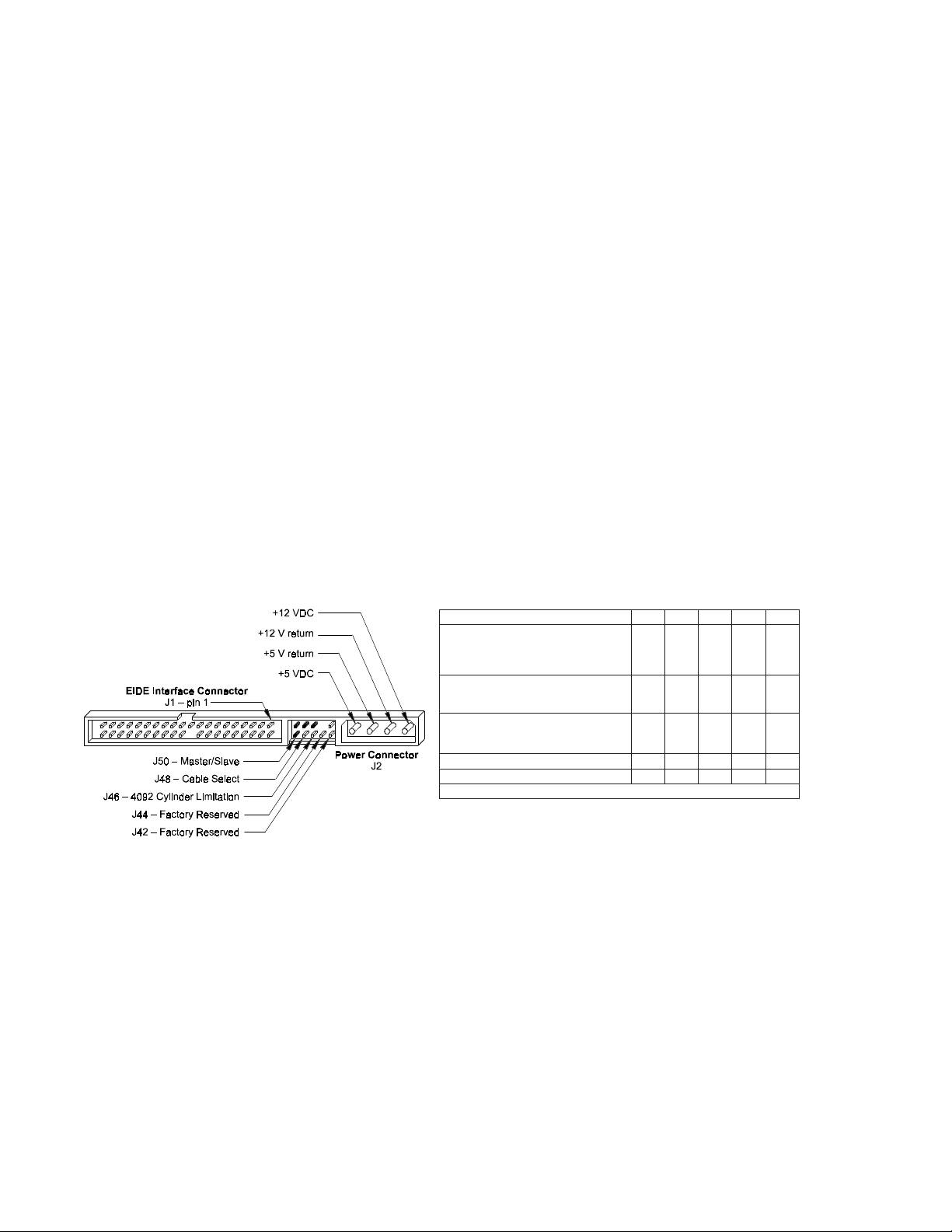
Interface Connector
All DiamondMax™ 6800 AT drives have a 40-pin ATA interface connector mounted on the PCBA. The drive
may connect directly to the host; or it can also accommodate a cable connection (max cable length:
18 inches).
Figure 5-1
Data Connector
Pin Description Summary
NIPLANGISNIPLANGIS
10-teseR20dnuorG
307DD408DD
506DD609DD
705DD8001DD
904DD0111DD
113DD2121DD
312DD4131DD
511DD6141DD
710DD8151DD
91dnuorG02)nipyek(
12QRAMD22dnuorG
32POTS:-WOID42dnuorG
52EBORTSH:YDRAMDH:-ROID62dnuorG
72EBORTSD:YDRAMDD:YDROI82LESC
92-KCAMD03dnuorG
13QRTNI23
331AD43-GAIDP
530AD632AD
73-0SC83-1SC
93-PSAD04dnuorG
61SCOI
etelosbO
5 – 1
Page 34

AT INTERFACE DESCRIPTION
Pin Description Table
EMANNIPNIPO/IEMANLANGISNOITPIRCSEDLANGIS
-TESER10I teseRtsoH .retfaevitcanidnapurewopgnirudevitcA.metsystsohehtmorflangisteseR
0DD71O/IsuBataDtsoH retsigerrofdesustib8rewoL.evirddnatsohneewtebsubatadlanoitcerid-ibtib61
1DD51O/I
2DD31O/I
3DD11O/I
4DD90O/I
5DD70O/I
6DD50O/I
7DD30O/I
8DD40O/I
9DD60O/I
01DD80O/I
11DD01O/I
21DD21O/I
31DD41O/I
41DD61O/I
51DD81O/I
QRAMD12O tseuqeRAMD eht,langissihtgnitressayB.srefsnartAMDrofKCAMDhtiwdesusilangissihT
-WOID
32I etirWO/ItsoH ehtnoretsigeraotsubatadtsohehtmorfatadskcolcebortsetirWfoegdegnisiR
POTS
-ROID
52I daeRO/ItsoH .subatadtsohehtotnoevirdehtnoretsigeramorfatadselbaneebortsdaeR
YDRAMDH
EBORTSH
YDROI
72O ydaeRlennahCO/I .selcycO/ItsohotnisetatstiawtresniotevirdehtybwolnevirdebyamlangissihT
YDRAMDD
EBORTSD
LESC82tceleSelbaC metsystsohnognilbaclaicepsseriuqeR.elbacaivnoitcelesevalS/retsaMrofdesU
-KCAMD92I egdelwonkcAAMD eht,langissihtgnitressayB.srefsnartAMDrofQRAMDhtiwdesusilangissihT
QRTNI13O tpurretnItsoH
61SCOI23O/Itib61eciveDetelosbO
-GAIDP43O/IcitsongaiDdessaP .edomretsaMninehwevirdottupnI;edomevalSninehwevirdybtuptuO
0AD53I suBsserddAtsoH .evirdehtniretsigeratcelesottsohehtmorfsserddayranibtib3
1AD33I
2AD63I
-0SC73I 0tceleSpihCtsoH .evirdehtnisretsigerkcolBdnammoCehtsseccaotdesutsohehtmorftcelespihC
-1SC83I 1tceleSpihCtsoH sihT.evirdehtnisretsigerlortnoCehtsseccaotdesutsohehtmorftcelespihC
-PSAD93O/I1evirD/evitcAevirD
DNG20A/NdnuorG.dnuorglangiS
91
22
42
62
03
04
YEK02A/NyeK.rotcennocecafretniehtgniyekrofdesuniP
.srefsnartatadrofdesustib61llA.srefsnartetybCCEdna
.tsohehtmorfdnaotderefsnartebotydaersiatadtahtsetacidnievird
.evird
.stsrubniatadAMDartlUgnirudydaerAMD
.stsrubtuoatadAMDartlUgnirudebortsataD
.stsrubtuoatadAMDartlUgnirudydaerAMD
.stsrubniatadAMDartlUgnirudebortsataD
.repmujtceleSelbaCfonoitallatsnidna
.elbaliavasiatadtahtgnitacidnisiroatadfotpiecerehtgnigdelwonkcasitsoh
tseuqeR
.xeh7F1-0F1sesserddaO/IfoedocedasilangissihT
.xeh7F3-6F3sesserddaO/Ifoedocedasilangis
tneserP
.tneserpsi1ecived
.tsohehtmorfnoitnettaseriuqerevirdehtnehwdetressatsohehtottpurretnI
tahtro,evitcasievirdatahtsetacidnihcihwtuptuorotcellocnepo,dexelpitlum-emiT
5 – 2
Page 35

AT INTERFACE DESCRIPTION
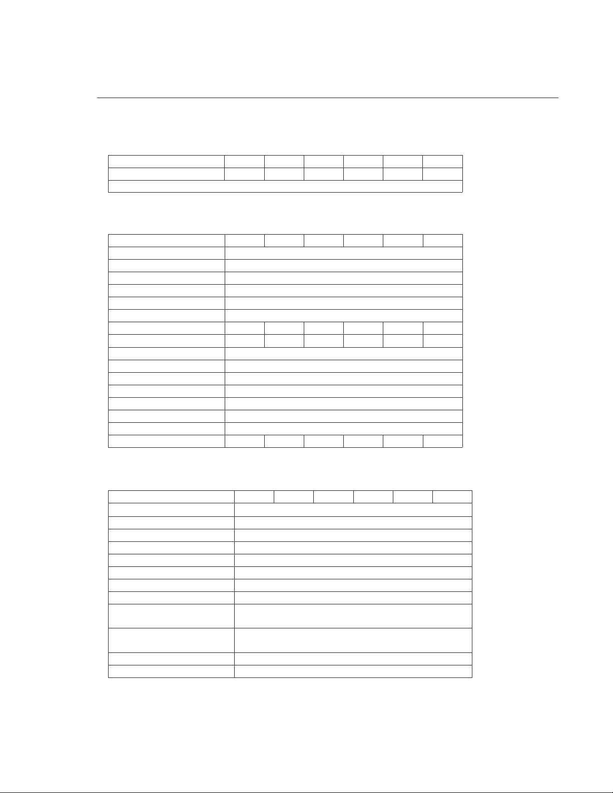
PIO Timing
SRETEMARAPGNIMIT0EDOM1EDOM2EDOM3EDOM4EDOM
0t)nim(emiTelcyCsn006sn383sn042sn081sn021
1t)nim(putes-WOID/-ROIDotdilavsserddAsn07sn05sn03sn03sn52
2t)nim(tib-61-WOID/-ROIDsn561sn521sn001sn08sn07
i2t)nim(emityrevocer-WOID/-ROID sn07sn52
3t)nim(putesatad-WOIDsn06sn54sn03sn03sn02
4t)nim(dlohatad-WOIDsn03sn02sn51sn01sn01
5t)nim(putesatad-ROIDsn05sn53sn02sn02sn02
6t)nim(dlohatad-WOIDsn5sn5sn5sn5sn5
Z6t)xam(etatsirtatad-ROIDsn03sn03sn03sn03sn03
9t)nim(dlohdilavsserddaot-WOID/-ROIDsn02sn51sn01sn01sn01
dRt)nim(evitcaYDROIotdilaVataDdaeR 00000
AtemiTputeSYDROIsn53sn53sn53sn53sn53
Bt)xam(htdiWesluPYDROIsn0521sn0521sn0521sn0521sn0521
Figure 5 - 2
PIO Data Transfer To/From Device
5 – 3
Page 36

AT INTERFACE DESCRIPTION
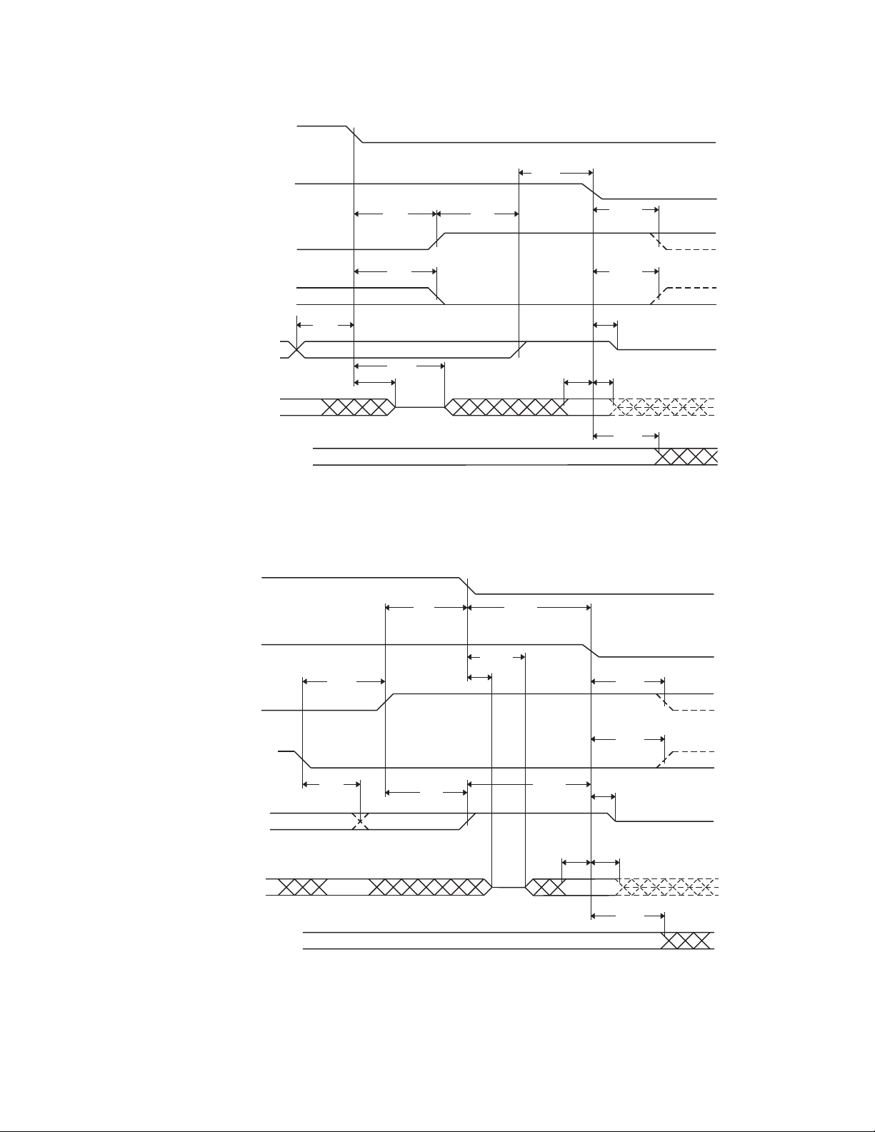
DMA Timing
SRETEMARAPGNIMIT0EDOM1EDOM2EDOM
0t)nim(emiTelcyCsn084sn051sn021
CtyaledQRAMDotKCAMD
Dt)nim(-WOID/-ROIDsn512sn08sn07
Et)nim(sseccaatad-ROIDsn051sn06
Ft)nim(dlohatad-ROIDsn5sn5sn5
Gt)nim(putesatad-WOID/-ROIDsn001sn03sn02
Ht)nim(dlohatad-WOIDsn02sn51sn01
It)nim(putes-WOID/-ROIDotKCAMD 000
Jt)nim(dlohKCAMDot-WOID/-ROIDsn02sn5sn5
rKt)nim(htdiweslupdetagen-ROIDsn05sn05sn52
wKt)nim(htdiweslupdetagen-WOIDsn512sn05sn52
rLt)xam(yaledQRAMDot-ROIDsn021sn04sn53
wLt)xam(yaledQRAMDot-WOIDsn04sn04sn53
Zt)xam(etatsirtot-KCAMDsn02sn52sn52
5 – 4
Figure 5 - 3
Multi-word DMA Data Transfer
Page 37

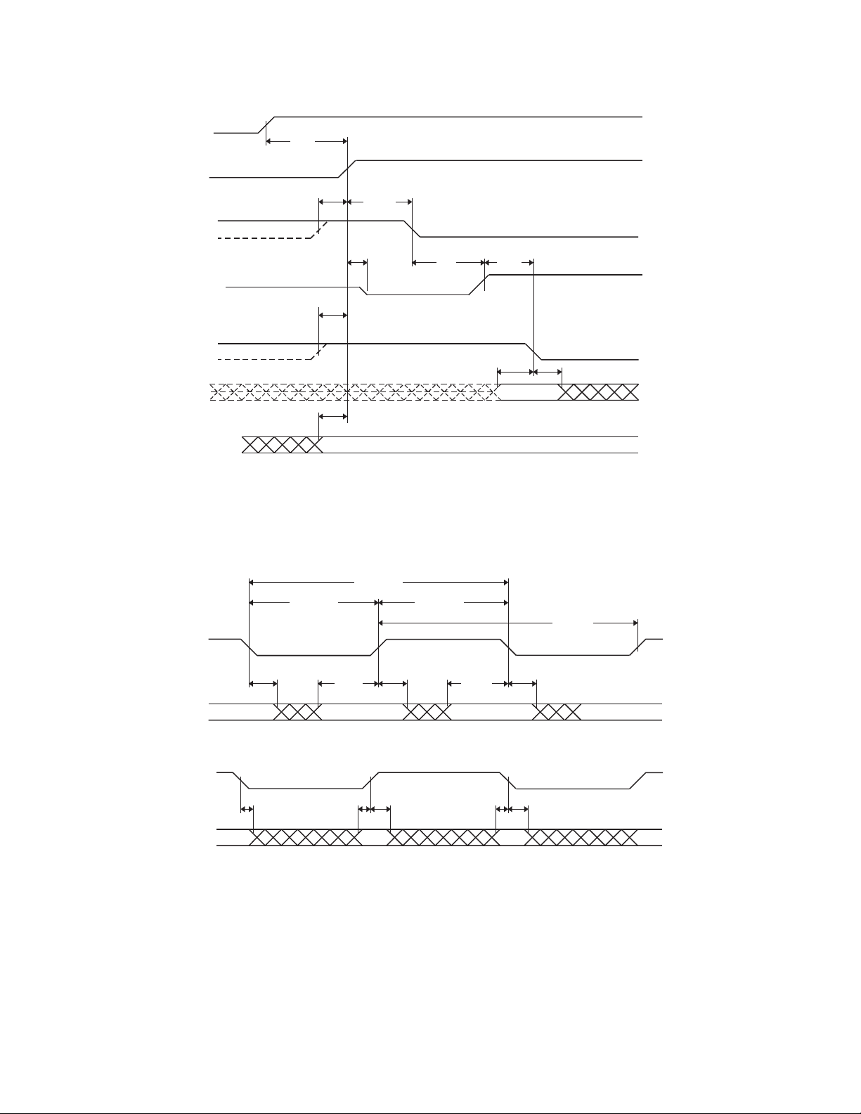
Ultra DMA Timing
SRETEMARAPGNIMIT )sdnocesonannisemitlla(
t
CYC
2t
CYC
t
SD
t
HD
t
SVD
t
HVD
t
SF
t
IL
t
ILM
t
IU
t
ZA
t
HAZ
t
DAZ
t
VNE
t
RS
t
SFR
t
PR
t
ZYDROI
t
YDROIZ
t
KCA
t
SS
emiTelcyC)egdeEBORTSotegdeEBORTSmorf(4115755
emitelcycowTroegdegnisirtxenotegdegnisirmorf(
emitputesataD)tneipicerta(5101707
emitdlohataD)tneipicerta( 555
EBORTStsriF)EBORTStsrifdnesotecivedrofemit(003200020071
)tnegarehtoehtyb
emitepolevnEehtnihtiwerasnoitisnartlangislortnoclla(
-KCAMD
gnippotssirednes
rednestaemitputesdilavataDgniebsubatadmorfemit(
)egdeEBORTSlitnudilav
rednestaemitdlohdilavataDegdeEBORTSmorfemit(
)dilavniogyamatadlitnu
emitkcolretnidetimiLybnoitcananeewtebdewollaemit(
muminimhtiwemitkcolretnI020202
emitkcolretnidetimilnU 000
)etatsdesaelermorf(
YDRAMDotEBORTSehterusneotemitesnopser(
emitEBORTS-lanif-ot-ydaeRyamsegdeEBORTSeromon(
emitesuap-ot-ydaeRemussayamtneipiceralitnuemit(
0EDOM1EDOM2EDOM
NIMXAMNIMXAMNIMXAM
EBORTSfoegdegnillaftxenotegdegnillafmorf)
esaelerotstuptuorofdewollaemitmumixaM010101
)emithcumsihtybepolevneKCAMD
)noitagen-YDRAMDgniviecerretfagnolsihttneseb
desaelerebotYDROIgniwollaerofebemitpu-lluP020202
YDROIgnivirderofebtiawllahsecivedemitmuminiM 000
fonoitagendnanoitressaerofebsemitdlohdnaputeS
ehtnehwnoitressaPOTSotegdeEBORTSmorfemiT
532651711
0784435
66602
noitcagniwollofehtdna,ecivedrotsohrehtie,tnegaeno
00510 0510051
020202
nogninrutsrevirdtuptuorofderiuqeremityaledmuminiM
000
020702070207
)gnisuapsitneipicerehtnehwesacesuapsuonorhcnys
)-YDRAMDfonoitagenretfadesuapsahrednesehttaht
050302
570605
061521001
020202
050505
AT INTERFACE DESCRIPTION
DMARQ
(device)
DMACK-
(host)
STOP
(host)
HDMARDY-
(host)
DSTROBE
(device)
DD(15:0)
DA0, DA1, DA2,
CS0-, CS1-
t
UI
t
t
t
t
ACK
ACK
ACK
t
ZIORDY
t
ENV
t
ENV
t
AZ
FS
t
ZAD
t
FS
t
ZAD
t
VDS
Figure 5 - 4
Initiating an Ultra DMA Data In Burst
t
DVH
5 – 5
Page 38

AT INTERFACE DESCRIPTION
DSTROBE
at device
DD(15:0)
at device
DSTROBE
at host
t
2CYC
t
CYC
t
DVH
t
DVS
t
DVH
t
CYC
t
DVS
t
DVH
t
2CYC
DD(15:0)
at host
DMARQ
(device)
DMACK-
HDMARDY-
DSTROBE
DD(15:0)
(host)
STOP
(host)
(host)
(device)
(device)
t
DH
t
DS
t
DH
Figure 5 - 5
Sustained Ultra DMA Data In Burst
t
SR
t
RFS
t
DS
t
RP
t
DH
5 – 6
Figure 5 - 6
Host Pausing an Ultra DMA Data In Burst
Page 39
DMARQ
(
)
(
)
(
)
device
DMACK-
(host)
STOP
(host)
HDMARDY-
(host)
DSTROBE
device
DD(15:0)
DA0, DA1, DA2,
CS0-, CS1-
AT INTERFACE DESCRIPTION
t
MLI
t
t
ACK
ACK
t
t
DVH
IORDYZ
t
LI
t
LI
t
SS
t
ZAH
t
AZ
t
LI
t
DVS
CRC
t
ACK
DMARQ
(device)
DMACK-
(host)
STOP
host
HDMARDY-
(host)
DSTROBE
(device)
DD(15:0)
DA0, DA1, DA2,
CS0-, CS1-
Figure 5 - 7
Device Terminating an Ultra DMA Data In Burst
t
LI
t
t
RP
t
RFS
AZ
t
LI
t
ZAH
t
MLI
t
MLI
t
DVS
CRC
t
ACK
t
ACK
t
IORDYZ
t
DVH
t
ACK
Figure 5 - 8
Host Terminating an Ultra DMA Data In Burst
5 – 7
Page 40
AT INTERFACE DESCRIPTION
(
)
DMARQ
(device)
DMACK-
host
t
UI
STOP
(host)
DDMARDY-
(device)
HSTROBE
(host)
DD(15:0)
(host)
DA0, DA1, DA2,
CS0-, CS1-
HSTROBE
at host
DD(15:0)
at host
t
ACK
t
ZIORDY
t
ACK
t
ACK
t
ENV
t
LI
Figure 5 - 9
Initiating an Ultra DMA Data Out Burst
t
2CYC
t
CYC
t
DVH
t
DVS
t
DVH
t
CYC
t
t
DVS
DVS
t
UI
t
DVH
t
2CYC
t
DVH
HSTROBE
at device
t
DH
t
DS
t
DH
t
DS
t
DH
DD(15:0)
at device
Figure 5 - 10
Sustained Ultra DMA Data Out Burst
5 – 8
Page 41

DMARQ
(device)
DMACK-
(host)
STOP
(host)
DDMARDY-
(device)
HSTROBE
(host)
DD(15:0)
(host)
t
RP
t
SR
t
RFS
Figure 5 - 11
Device Pausing an Ultra DMA Data Out Burst
AT INTERFACE DESCRIPTION
DMARQ
(device)
DMACK-
(host)
STOP
(host)
DDMARDY-
(device)
HSTROBE
(host)
DD(15:0)
(host)
DA0, DA1, DA2,
CS0-, CS1-
t
LI
t
MLI
t
t
SS
t
LI
LI
t
DVS
t
t
ACK
ACK
t
IORDYZ
t
DVH
CRC
t
ACK
Figure 5 - 12
Host Terminating an Ultra DMA Data Out Burst
5 – 9
Page 42

AT INTERFACE DESCRIPTION
(
)
(
)
,
DMARQ
(device)
DMACK-
(host)
STOP
host
DDMARDY-
device
HSTROBE
(host)
DD(15:0)
(host)
DA0, DA1, DA2,
CS0-
CS1-
t
LI
t
RP
t
RFS
t
LI
t
MLI
t
MLI
t
DVS
CRC
Figure 5 - 13
Device Terminating an Ultra DMA Data Out Burst
t
ACK
t
IORDYZ
t
ACK
t
DVH
t
ACK
5 – 10
Page 43

HOST SOFTWARE INTERFACE
SECTION 6
Host Software Interface
The host communicates with the drive through a set of controller registers accessed via the host’s I/O ports.
These registers divide into two groups: the Task File, used for passing commands and command parameters and
the Control/Diagnostic registers.
Task File Registers
The Task File consists of eight registers used to control fixed disk operations. The host accesses each register
by the I/O port address shown in this Task File register map:
TROPO/IDAERETIRW
h0F1retsigeRataDretsigeRataD
h1F1retsigeRrorrEretsigeRserutaeF
h2F1tnuoCrotceStnuoCrotceS
h3F1rebmuNrotceSrebmuNrotceS
h4F1woLrednilyCwoLrednilyC
h5F1hgiHrednilyChgiHrednilyC
h6F1)HDS(daeH/evirD)HDS(daeH/evirD
h7F1retsigeRsutatSretsigeRdnammoC
Data Register
Provides access to the drive’s sector buffer for read and write operations. With the exception of ECC byte
transfers (which, during Read long and Write long commands, are 8 bits wide), data transfers through the
Data register are all 16 bits wide.
Error Register
A read-only register containing specific information regarding the previous command. Data interpretation
differs depending on whether the controller is in operational or diagnostic mode. A power up, reset,
software reset, or receipt of a diagnostic command sets the controller into diagnostic mode. This mode
invalidates contents of the Status register. The contents of the Error register reflect a completion code.
Issuing any command (apart from a Diagnostic command) places the controller into operational mode.
In operational mode, the Error register is valid only when the Error bit in the Status register is set. The bit
definitions for operational mode follow:
765432 10
0CCE0 FNDI0TRBA0KTFNMA
ecafretnI
CRC
Interface CRC
Data ECC Error
Firmware Problem
ID Not Found
Aborted Command
Track 0 Error
Address Mark Not Found
ataD
rorrECCE
– An interface CRC error occurred during an Ultra DMA transfer.
– An non-correctable ECC error occurred during a Read Sector command.
– Indicates a firmware problem was detected, (e.g., invalid interrupt, divide overflow).
– Either a matching ID field not found, or a CRC error occurred.
– Invalid commands, write fault, no seek complete, or drive not ready.
– Track 0 was not found during execution of a Restore command.
toN
desU
– The Address Mark could not be found after an ID match.
DI
dnuoFtoN
toN
desU
detrobA
dnammoC
0kcarT
rorrE
sserddA
toNkraM
dnuoF
Features Register
Enables or disables features through the Set Features command.
6 – 1
Page 44

HOST SOFTWARE INTERFACE
Sector Count Register
Holds the number of sectors to be sent during a Read or Write command, and the number of sectors per
track during a Format command. A value of zero in this register implies a transfer of 256 sectors. A multisector operation decrements the Sector Count register. If an error occurs during such an operation, this
register contains the remaining number of sectors to be transferred.
Sector Number Register
Holds the starting sector number for any disk operation. The register is updated as each sector is processed in
a multi-sector operation.
Cylinder Number Registers
Two 8-bit Cylinder Number registers (Low and High) specify the starting cylinder for disk operation.
Device/Head Register
Used to specify the drive and head number to be operated on during any disk operations. Within the
context of a Set Parameters command, this register specifies the maximum number of heads on the drive.
Bit definitions follow:
765432 10
1ABL1VRD3SH2SH1SH0SH
edoM
evirD
tceleStceleS
daeH
tceleS
daeH
tceleS
daeH
tceleS
Select LBA Mode
the Task File register contents are defined as follows for the Read/Write and translate command:
Drive Select
Head Select
– Enabling this bit for commands not supported by LBA mode will abort the selected command. When set,
STNETNOCSTIBABL
rebmuNrotceS7-0
woLrednilyC51-8
hgiHrednilyC32-61
daeH/evirD72-42
– Set to 0 to select the master drive; set to 1 to select the slave drive.
– Specifies the binary coded address of the head to be selected.
Status Register
Contains results of the last command executed, and the drive’s status. The other seven Task File registers may
be read only when bit 7 (BUSY) of the Status register is low. Reading any of the Task File registers when
BUSY is high returns the value of the Status register. Reading the Status register also clears any interrupt
request to the host. Bit definitions follow:
7654 3210
YSUBYDRDFDCSDQRD00 RRE
rellortnoC
ysuB
Controller Busy
execution. After a command, this bit resets.
Device Ready
Device Fault
Device Seek Complete
Data Request
Error
– The Error bit sets when the previous command has completed with a non-recoverable error.
eciveD
ydaeR
– Goes active when a command is written to the Command register, indicating controller task
– Indicates that the drive is ready for commands. If drive ready is not present, all commands abort.
– Indicates the drive’s detection of a write fault condition, causing all commands to abort.
– Indicates that the drive’s sector buffer is ready for data transfer.
eciveD
tluaF
– Signifies a seek completion, and that the drive is on track.
keeSeciveD
etelpmoC
ataD
tseuqeR
rorrE
6 – 2
Page 45

HOST SOFTWARE INTERFACE
Command Register
Contains code for the command to be performed. Additional command information should be written to the
task file before the Command register is loaded. When this register is written, the BUSY bit in the Status
register sets, and interrupt request to the host clears; invalid commands abort. (Detailed information on interface
commands is given in Section 7.) Hex values for valid command formats follow:
Read Commands
Read Sector(s) 20h Normal reads; retries enabled
Read Verify Sector(s) 40h Retries enabled
Read Sector Buffer E4h
Read Multiple C4h
Read DMA C8h
Write Commands
Write Sector(s) 30h Normal writes; retries enabled
Write Verify Sector(s) 3Ch
Write Sector Buffer E8h
Write Multiple C5h
Write DMA CAh
21h Normal reads; retries disabled
22h Read Long; retries enabled
23h Read Long; retries disabled
41h Retries disabled
C9h No retries
31h Normal writes; retries disabled
32h Write Long; retries enabled
33h Write Long; retries disabled
CBh No retries
Mode Set/Check Commands
Set Features EFh
Set Multiple Mode C6h
Power Mode Commands
Standby Immediate 94/E0h Stops drive spindle; do not change time-out value
Idle Immediate 95/E1h Starts spindle; do not change time-out value
Standby 96/E2h Stops spindle; change time-out value
Idle 97/E3h Starts spindle; change time-out value
Check Power Mode 98/E5h
Set Sleep Mode 99/E6h
Initialization Commands
Identify Drive ECh
Initialize Drive Parameters 91h
Re-calibrate 1xh
Seek, Format, and Diagnostic Commands
Seek 7xh
Format Track 50h
Execute Drive Diagnostic 90h
S.M.A.R.T. Commands
Execute S.M.A.R.T. B0h
6 – 3
Page 46

HOST SOFTWARE INTERFACE
Summary
etarbilaceR 0001xxxx NNNN D
)s(rotceSdaeR 00 1000Lx NYYY Y
AMDdaeR 1100 100x NYYY Y
)s(rotceSetirW 001100Lx NYYY Y
AMDetirW 1100101x NYYY Y
)s(rotceSyfireVetirW 00 111100 NYYY Y
)s(rotceSyfireVdaeR 0100000x NYYY Y
kcarTtamroF 01010000 NNNY Y
keeS 0111xxxx NNYY Y
citsongaiDetucexE 100 10000 NNNN D
sretemaraPezilaitinI 100 10001 NYNN Y
reffuBrotceSdaeR 11 10 0 10 0 NNNN D
reffuBrotceSetirW 11 10 10 0 0 NNNN D
evirDyfitnedI 11 10 1 10 0 NNNN D
serutaeFteS 11101111 YNNN D
elpitluMdaeR 11000100 NYYY Y
elpitluMetirW 11000 101 NYYY Y
edoMelpitluMteS 11000110 NYNN D
DESUSRETEMARAPEDOCDNAMMOCEMANDNAMMOC
7b6b5b4b3b2b1b0bFCSNSC HDS
EULAVREMITDOIREPTUO-EMIT
0delbasidtuo-emiT
042-1sdnoces)5*eulav(
152-142setunim)03*)042-eulav((
252setunim12
352sruoh01=doirepeuqinurodneV
452devreseR
552sdnoces51,setunim12
6 – 4
Page 47

HOST SOFTWARE INTERFACE
Control Diagnostic Registers
These I/O port addresses reference three Control/Diagnostic registers:
TROPO/IDAERETIRW
h6F3sutatSetanretlAlortnoCksiDdexiF
h7F3tupnIlatigiDdesutoN
Alternate Status Register
Contains the same information as the Status register in the Task File. However, this register may be read at
any time without clearing a pending interrupt.
Device Control Register
Contains the software Reset and Enable bit to enable interrupt requests to the host. Bit definitions follow:
765432 10
00000 TSRSNEI0
teseRelbanEQRI
Reset – Setting the software Reset bit holds the drive in the reset state. Clearing the bit re-enables the drive.
The software Reset bit must be held active for a minimum of 5 µsec.
IRQ Enable
to 1, IRQ14 is tri-stated, and interrupts to the host are disabled. Any pending interrupt occurs when the bit is set to 0.
The default state of this bit after power up is 0 (interrupt enabled).
– Setting the Interrupt Request Enable to 0 enables the IRQ 14 signal to the host. When this bit is set
Digital Input Register
Contains information about the state of the drive. Bit definitions follow:
765432 10
xGW-3SH-2SH-1SH-0SH-1SD-0SD
devreseR
etaG
daeH
3tceleS
daeH
2tceleS
daeH
1tceleS
daeH
0tceleS
evirD
1tceleS
evirD
0tceleS
Bit 7 of the host data bus is not driven when this register is read.
-Write Gate
-Head Select 3 through -Head Select 0
-Drive Select 1
-Drive Select 0
– Reflects the state of the active low write gate signal on the drive.
– Represents the ones complement of the currently selected head number.
– Is 0 if drive 1 selected; 1 otherwise.
– Is 0 if drive 0 selected; 1 otherwise.
6 – 5
Page 48

HOST SOFTWARE INTERFACE
Reset and Interrupt Handling
Reset Handling
One of three different conditions may cause a reset: power on, hardware reset or software reset. All three
cause the interface processor to initialize itself and the Task File registers of the interface. A reset also causes a
set of the Busy bit in the Status register. The Busy bit does not clear until the reset clears and the drive
completes initialization. Completion of a reset operation does not generate a host interrupt.
Task File registers are initialized as follows:
Error 1
Sector Count 1
Sector Number 1
Cylinder Low 0
Cylinder High 0
Drive/Head 0
Interrupt Handling
The drive requests data transfers to and from the host by asserting its IRQ 14 signal. This signal interrupts the
host if enabled by bit 1 (IRQ enable) of the Fixed Disk Control register.
Clear this interrupt by reading the Status register, writing the Command register, or by executing a host
hardware or software reset.
6 – 6
Page 49

Interface Commands
The following section describes the commands (and any parameters necessary to execute them),
as well as Status and Error register bits affected.
Read Commands
Read Sector(s)
Read Verify Sector(s)
Read Sector Buffer
Read DMA
Multi-word DMA
Ultra DMA
Read Multiple
Set Multiple
Write Commands
Write Sector(s)
Write Verify Sector(s)
Write Sector Buffer
Write DMA
Multi-word DMA
Ultra DMA
Write Multiple
INTERFACE COMMANDS
SECTION 7
Set Feature Commands
Set Features Mode
Power Mode Commands
Standby Immediate
Idle Immediate
Standby
Idle
Check Power Mode
Set Sleep Mode
Default Power-on Condition
Initialization Commands
Identify Drive
Initialize Drive Parameters
7 – 1
Page 50

INTERFACE COMMANDS
Read Commands
Read Sector(s)
Reads from 1 to 256 sectors, as specified in the Command Block, beginning at the specified sector. (A sector
count of 0 requests 256 sectors.) Immediately after the Command register is written, the drive sets the BSY
bit and begins execution of the command. If the drive is not already on the desired track, an implied seek is
performed.
Once at the desired track, the drive searches for the data address mark of the requested sector. The data
address mark must be recognized within a specified number of bytes, or the Data Address Mark Not Found
error will be reported. Assuming the data address mark is found:
1. The data field is read into the sector buffer.
2. Error bits are set (if an error was encountered).
3. The DRQ bit is set.
4. An interrupt is generated.
The DRQ bit is always set, regardless of the presence or absence of an error condition after the sector.
Upon command completion, the Command Block registers contain the numbers of the cylinder, head and
sector of the last sector read. Back-to-back sector read commands set DRQ and generate an interrupt when
the sector buffer is filled at the completion of each sector. The drive is then ready for the data to be read by
the host. DRQ is reset and BSY is set immediately when the host empties the sector buffer.
If an error occurs during Read Sector commands, the read terminates at the sector where the error occurred.
The host may then read the Command Block to determine the nature of that error, and the sector where it
happened. If the error type is a correctable or an non-correctable data error, the flawed data is loaded into
the sector buffer.
A Read Long command sets the Long bit in the command code and returns the data and the ECC bytes in
the data field of the specified sector. During a Read Long, the drive does not check the ECC bytes to
determine if there has been a data error. The Read Long command is limited to single sector requests.
Read Verify Sector(s)
Identical to the Read Sector(s) command, except that:
1. DRQ is never set,
2. No data is transferred back to the host and
3. The long bit is not valid.
7 – 2
Page 51

INTERFACE COMMANDS
Read DMA
Multi-word DMA
Identical to the Read Sector(s) command, except that
1. The host initializes a slave-DMA channel prior to issuing the command,
2. Data transfers are qualified by DMARQ and are performed by the slave-DMA channel
and
3. The drive issues only one interrupt per command to indicate that data transfer has
terminated and status is available.
Ultra DMA
With the Ultra DMA Read protocol, the control signal (DSTROBE) that latches data from DD(15:0) is
generated by the devices which drives the data onto the bus. Ownership of DD(15:0) and this data strobe
signal are given DSTROBE to the drive during an Ultra DMA data in burst.
During an Ultra DMA Read burst, the drive always moves data onto the bus, and, after a sufficient time to
allow for propagation delay, cable settling, and setup time, the sender shall generate a DSTROBE edge to
latch the data. Both edges of DSTROBE are used for data transfers.
Any unrecoverable error encountered during execution of a Read DMA command terminates data transfer
after the transfer of all sectors prior to the sector where the error was detected. The sector in error is not
transferred. The drive generates an interrupt to indicate that data transfer has terminated and status is
available. The error posting is identical to the Read Sector(s) command.
Read Multiple
Performs similarly to the Read Sector(s) command, except that for each READ MULTIPLE command data
transfers are multiple sector blocks and the Long bit is not valid.
Execution is also similar to that of the READ SECTOR(S) command, except that:
1. Several sectors are transferred to the host as a block, without intervening interrupts.
2. DRQ qualification of the transfer is required only at the start of each block, not of each sector.
The block count consists of the number of sectors to be transferred as a block. (The block count is
programmed by the Set Multiple Mode command, which must be executed prior to the Read Multiple
command.) READ LONG command is limited to single sector requests.
When the Read Multiple command is issued, the Sector Count register contains the number of sectors
requested — not the number of blocks or the block count. If the number of sectors is not evenly divisible
by the block count, as many full blocks as possible are transferred, followed by a final, partial block transfer.
This final, partial block transfer is for N sectors, where N = (sector count) modulo (block count)
The Read Multiple operation will be rejected with an Aborted Command error if attempted:
1. Before the Set Multiple Mode command has been executed, or
2. When Read Multiple commands are disabled.
The controller reports disk errors encountered during Read Multiple commands at the start of the block or
partial block transfer. However, DRQ still sets, and the transfer occurs normally, along with the transfer of
any corrupt data. Remaining block data from the following the sector in error is not valid.
If the Sector Count register contains 0 when the Set Multiple Mode command is issued, Read Multiple and
Write Multiple commands are disabled; no error is returned. Once the appropriate action has been taken, the
controller resets BSY and generates an interrupt. At power up, or after a hardware or software reset, Read
Multiple and Write Multiple commands are disabled by default.
7 – 3
Page 52

INTERFACE COMMANDS
Set Multiple Mode
Enables the controller to perform Read and Write Multiple operations, and establishes the block count for
these commands. Before issuing this command, the Sector Count register should be loaded with the number
of sectors per block. The drives support block sizes of 2, 4, 8 and 16 sectors.
When this command is received, the controller sets BSY and examines the Sector Count register contents. If
they contain a valid and supported block count value, that value is loaded for all subsequent Read and Write
Multiple commands, and execution of those commands is enabled. An invalid and unsupported block count
in the register results in an Aborted Command error and disallows Read Multiple and Write Multiple
commands.
Write Commands
Write Sector(s)
Writes from 1 to 256 sectors, beginning at a sector specified in the Command Block. (A sector count of 0
requests 256 sectors.)
When the Command register is written, the drive sets the DRQ bit and waits for the host to fill the sector
buffer with the data to be written. An interrupt is not generated to start the first buffer fill operation.
Once the buffer is full, the drive resets DRQ, sets BSY, and begins command execution. If the drive is not
already on the desired track, an implied seek is performed.
The data loaded in the buffer is written to the data field of the sector, followed by the ECC bytes. Upon
command completion, the Command Block registers contain the cylinder, head and sector number of the
last sector written. The next time the buffer is ready to be filled during back-to-back Write Sector
commands, DRQ is set and an interrupt is generated.
After the host fills the buffer, DRQ is reset and BSY is set. If an error occurs, Write Sector operations
terminate at the sector containing the error.
The Command Block registers then contain the numbers of the cylinder, head and sector where the error
occurred. The host may read the Command Block to determine the nature of that error, and on which
sector it happened. A Write Long may be executed by setting the Long bit in the command code. The
Write Long command writes the data and the ECC bytes directly from the sector buffer; the drive itself does
not generate the ECC bytes. Restrict Write Long commands to PIO Mode 0.
Write Verify Sector(s)
Identical to the Write Sector(s) command, except that the requested sectors are verified immediately after
being written. The verify operation reads (without transferring), and checks for data errors. Any errors
encountered during this operation are reported.
Write Sector Buffer
Allows the host to overwrite the contents of the drive’s sector buffer with a selected data pattern. When this
command is received, the drive:
1. Sets BSY,
2. Sets up the sector buffer for a write operation,
3. Sets DRQ,
4. Resets BSY and
5. Generates an interrupt.
7 – 4
The host may then write up to 256 words of data to the buffer. A disk write task begins to store the host
data to disk. Host write commands continue to be accepted and data transferred to the buffer until either
the write command stack is full or the data buffer is full. The drive may reorder write commands to optimize
drive throughput.
Page 53

INTERFACE COMMANDS
Write Multiple
Performs similarly to the Write Sector(s) command, except that:
1. The controller sets BSY immediately upon receipt of the command,
2. Data transfers are multiple sector blocks and
3. The Long bit and Retry bit is not valid.
Command execution differs from Write Sector(s) because:
1. Several sectors transfer to the host as a block without intervening interrupts.
2. DRQ qualification of the transfer is required at the start of the block, not on each sector.
The block count consists of the number of sectors to be transferred as a block and is programmed by the Set
Multiple Mode command, which must be executed prior to the Write Multiple command. When the Write
Multiple command is issued, the Sector Count register contains the number of sectors requested — not the
number of blocks or the block count.
If the number of sectors is not evenly divisible by the block count, as many full blocks as possible are
transferred, followed by a final, partial block transfer. This final, partial block transfer is for N sectors, where
N = (sector count) modulo (block count)
The Write Multiple operation will be rejected with an Aborted Command error if attempted:
1. Before the Set Multiple Mode command has been executed, or
2. When Write Multiple commands are disabled.
All disk errors encountered during Write Multiple commands report after the attempted disk write of the
block or partial block in which the error occurred.
The write operation ends with the sector in error, even if it was in the middle of a block. When an error
occurs, subsequent blocks are not transferred. When DRQ is set at the beginning of each full and partial
block, interrupts are generated.
Write DMA
Multi-word DMA
Identical to the Write Sector(s) command, except that:
1. The host initializes a slave-DMA channel prior to issuing the command,
2. Data transfers are qualified by DMARQ and are performed by the slave-DMA channel and
3. The drive issues only one interrupt per command to indicate that data transfer has terminated
at status is available.
Ultra DMA
With the Ultra DMA Write protocol, the control signal (HSTROBE) that latches data from DD(15:0) is
generated by the devices which drives the data onto the bus. Ownership of DD(15:0) and this data
strobe signal are given to the host for an Ultra DMA data out burst.
During an Ultra DMA Write burst, the host always moves data onto the bus, and, after a sufficient time to
allow for propagation delay, cable settling, and setup time, the sender shall generate a HSTROBE edge to
latch the data. Both edges of HSTROBE are used for data transfers.
Any error encountered during Write DMA execution results in the termination of data transfer. The drive
issues an interrupt to indicate that data transfer has terminated and status is available in the error register.
The error posting is the same as that of the Write Sector(s) command.
7 – 5
Page 54

INTERFACE COMMANDS
Set Feature Commands
Set Features Mode
Enables or disables features supported by the drive. When the drive receives this command it:
1. Sets BSY,
2. Checks the contents of the Features register,
3. Clears BSY and
4. Generates an interrupt.
If the value of the register is not a feature supported by the drive, the command is aborted.
The acceptable values in the Features register are defined as follows:
EULAVNOITPIRCSED
*h20ehcacetirwdelbanE
h30retsigertnuoCrotceSnieulavnodesabedomrefsnartteS
h44 ehtnideificepssdnammocgnoLetirW/gnoLdaeRnodedneppaatadfohtgneL
h55erutaefdaeha-kooldaerelbasiD
*h66stluafedno-rewopotgnitreverelbasiD
h28ehcacetirwelbasiD
*hAAerutaefdaeha-kooldaerelbanE
*hBB sdnammocgnoLetirW/gnoLdaeRnodedneppaatadcificepsrotxaMfosetyb4
hCCstluafedno-rewopotgnitreverelbanE
*.tluafedybpurewoptadelbanE
noitamrofnieciveDyfitnedI
7 – 6
Page 55

INTERFACE COMMANDS
Power Mode Commands
Standby Immediate – 94h/E0h
Spin down and do not change time out value. This command will spin the drive down and cause the drive
to enter the STANDBY MODE immediately. If the drive is already spun down, the spin down sequence is
not executed.
Idle Immediate – 95h/E1h
Spin up and do not change time out value. This command will spin up the spin motor if the drive is spun
down, and cause the drive to enter the IDLE MODE immediately. If the drive is already spinning, the spin
up sequence is not executed. The actuator is parked and some circuits are powered off.
Standby – 96h/E2h
Spin down and change time out value. This command will spin the drive down and cause the drive to enter
the STANDBY MODE immediately. If the drive is already spun down, the spin down sequence is not
executed. A non-zero value placed in the sector count register will enable the Automatic Power Down
sequence. The timer will begin counting down when the drive returns to the IDLE MODE. A value of zero
placed in the sector count register will disable the Automatic Power Down sequence.
Idle – 97h/E3h
Spin up and change time out value. This command will spin-up the spin motor if the drive is spun-down.
If the drive is already spinning, the spin up sequence is not executed. A non-zero value placed in the Sector
Count register will enable the Automatic Power Down sequence and their timer will begin counting down
immediately. A value of zero placed in the Sector Count register will disable the Automatic Power Down
sequence. The actuator is parked and some circuits are powered off.
Check Power Mode – 98h/E5h
This command returns a code in the Sector Count register that determines the current Power Mode status of
the drive. If the drive is in, going to, or recovering from the STANDBY MODE the drive sets the Sector
Count register to OOh. If the drive is in the IDLE MODE or ACTIVE MODE, the drive sets the Sector
Count register to FFh.
Set Sleep Mode – 99h/E6h
This command will spin the drive down and cause the drive to enter the SLEEP MODE immediately. If the
drive is already spun down, the spin down sequence is not executed.
Note: The only way to recover from SLEEP MODE is with a software reset or a hardware reset.
Default Power-on Condition
The drive’s default power on condition is the ACTIVE MODE.
Upon receiving a Power Mode command, except the SLEEP MODE command, the drive sets BSY and
performs the requested power operation. Once the requested Power Mode change has begun, the drive
resets BSY and generates an interrupt - without waiting for the drive to spin up or spin down. Upon
receiving a SLEEP MODE command the drive is spun down, and when it is stopped, the drive resets BSY
and generates an interrupt.
7 – 7
Page 56

INTERFACE COMMANDS
When enabling the Automatic Power Down sequence, the value placed in the Sector Count register is
multiplied by five seconds to obtain the Time-out Interval value. If no drive commands are received from
the host within the Time-out Interval, the drive automatically enters the STANDBY mode. The minimum
value is 5 seconds.
0delbasidtuo-emiT
252setunim12
35201=doirepeuqinurodneV
452devreseR
552sdnoces51,setunim12
While the drive is in STANDBY MODE, any commands received from the host are accepted and executed
as they would in normal operation, except that the spin motor is started if required to execute a disk
command. Under these conditions, the drive will set BSY when command processing would normally begin
and will leave BSY set until the drive comes up to speed and the disk command can be executed. Disk
commands issued while the drive is in STANDBY MODE, restarts the Time-out Interval after completing
the command. A reset must be issued before attempting to issue any commands while the drive in
SLEEP MODE.
EULAVREMITDOIREPTUO-EMIT
042-1sdnoces)5*eulav(
152-142setunim)03*)042-eulav((
sruoh
7 – 8
Page 57

INTERFACE COMMANDS
Initialization Commands
Identify Drive
Allows the host to receive parameter information from the drive.
When the command is received, the drive:
1. Sets BSY,
2. Stores the required parameter information in the sector buffer,
3. Sets the DRQ bit and
4. Generates an interrupt.
The host may then read the information out of the sector buffer. Parameter words in the buffer follow.
Note that all reserved bits or words should be zeroes.
DROWNOITPIRCSEDTNETNOC
0noitarugifnoclareneG
)IPATA=1,ATA=0(ecived=51
desuton=8-41
atadaidemelbavomer=1,7
ecivedro/dnarellortnocelbavomerton=1,6
devreser=1-5
0
1srednilycforebmuN
2devreseR
3sdaehlacigolforebmuN
5-4desutoN
6kcartrepsrotceslacigolforebmuN
9-7desutoN
91-01)sretcarahcIICSA04(rebmunlairesevirD
02desutoN
12)deificepston=h0000(stnemercnietyb215niezisreffuB
22 sdnammocgnoLetirW/daeRnoelbaliavasetybcificepsrotxaMforebmuN
62-32)sretcarahcIICSA8(noisivererawmriF
64-72)sretcarahcIICSA04(rebmunledoM
74 sdnammocelpitlumetirwdnadaernotpurretnirepderrefsnartebnactahtsrotcesforebmunmumixaM
84devreseR
94seitilibapaC
devreser=41-51
)troppusedomOIPdecnavda(devreser=21
detroppusebyamYDROI=0,detroppusYDROI=1,11
delbasidebnacYDROI=1,01
devreser=8-9
desuton=0-7
)cificepsrotxaMeraseulav=0,detroppuseradradnatssihtnideificepssaseulav=1(remitybdnats=31
7 – 9
Page 58

INTERFACE COMMANDS
DROWNOITPIRCSEDTNETNOC
05devreseR
15edomrefsnartatadOIP=8-51
25edomrefsnartatadAMD=8-51
35devreser=51
45srednilyclacigoltnerrucforebmuN
55sdaehlacigoltnerrucforebmuN
65kcartrepsrotceslacigolforebmuN
85-75srotcesniyticapactnerruC
95devreser=9-51
16-06)ylnoedomABL(srotceselbasserddaresuforebmunlatoT
26devreseR
36evitcaedomrefsnartAMDdrow-itluM=8-51
46devreser=8-51
56 )sdnocesonanniemitelcyc=0-51(emitelcycrefsnartAMDdrow-itlummuminiM
66 )sdnocesonanniemitelcyc=0-51(emitelcycrefsnartAMDdrow-itlumdedemmocers'rerutcafunaM
76 )sdnocesonanniemitelcyc=0-51(lortnocwolftuohtiwemitelcycrefsnartOIPmuminiM
86 )sdnocesonanniemitelcyc=0-51(lortnocwolfYDROIhtiwemitelcycrefsnartOIPmuminiM
97-96devreseR
08devreser=5-51
18rebmunnoisrevroniM
28 .detroppustonnoitacifitontesdnammochFFFFroh0000=38dna28sdrowfI.detroppustesdnammoC
desuton=0-7
desuton=0-7
dilavtonera88sdrownidetroppussdleifeht=0,dilavera88sdrownidetroppussdleifeht=1,2
dilavtonera07-46sdrownistropersdleifeht=0,dilavera07-46sdrownistropersdleifeht=1,1
dilavtonera85-45sdrownistropersdleifeht=0,dilavera85-45sdrownistropersdleifeht=1,0
dilavsignittesrotceselpitlum=1,8
elpitluMetirW/daeRnotpurretnirepderrefsnartrepnactahtsrotcesforebmunrofgnittestnerruc=hxx0-7
dnammoc
detroppussedomrefsnartAMDdrow=itluM=0-7
detroppussedomrefsnartOIPdecnavda=0-7
4-ATAstroppus=1,4
3-ATAstroppus=1,3
2-ATAstroppus=1,2
1-ATAstroppus=1,1
devreser,0
dnammocAMDeciveDyfitnedIehtstroppus=1,51
dnammocPONehtstroppus=1,41
dnammocreffuBetirWehtstroppus=1,31
dnammocreffuBdaeRehtstroppus=1,21
dnammocreffuBdaeRehtstroppus=1,11
teserutaefaerAdetcetorP-tsoHstroppus=1,01
dnammocteseReciveDehtstroppus=1,9
tpuretnIecivreSstroppus=1,8
tpuretnIesaeleRstroppus=1,7
daehAkooLstroppus=1,6
ehcaCetirWstroppus=1,5
teserutaefdnammoctekcaPehtstroppus=1,4
dnammocerutaeftnemeganaMrewoPehtstroppus=1,3
dnammocerutaefelbavomeRehtstroppus=1,2
dnammocerutaefytiruceSehtstroppus=1,1
teserutaefTRAMSehtstroppus=1,0
7 – 10
Page 59

DROWNOITPIRCSEDTNETNOC
38 tonnoitacifitontesdnammochFFFFroh0000=48dna38,28sdrowfI.detroppusstesdnammoC
48 tesdnammochFFFFroh0000=68dna58,48sdrowfI.detroppussnoisnetxetesdnammoC
58 tonnoitacifitontesdnammochFFFFroh0000=68dna58,48sdrowfI.delbanetesdnammoC
68 tonnoitacifitontesdnammochFFFFroh0000=78dna68,58sdrowfI.delbanestesdnammoC
78 tonnoitacifitontesdnammochFFFFroh0000=78dna68,58sdrowfI.delbanestesdnammoC
88AMDartlU
INTERFACE COMMANDS
.detroppus
orezotderaelcebllahs=51
enoottesebllahs=41
devreser=1-31
dnammocedocorciMdaolnwoDstroppus=1,0
.detroppustonnoitacifiton
orezotderaelcebllahs=51
enoottesebllahs=41
devreser=0-31
.detroppus
delbanednammocAMDeciveDyfitnedI=1,51
delbanednammocPON=1,41
delbanednammocreffuBetirW=1,31
delbanednammocreffuBdaeR=1,21
delbanednammocyfireVetirW=1,11
delbaneteserutaefaerAdetcetorPtsoH=1,01
delbanednammocteseReciveD=1,9
delbanetpurretnIecivreS=1,8
delbanetpurretnIesaeleR=1,7
delbanedaehAkooL=1,6
delbaneehcaCetirW=1,5
delbaneteserutaefdnammoctekcaP=1,4
delbaneteserutaeftnemegnaMrewoP=1,3
delbaneteserutaefelbavomeR=1,2
delbaneteserutaefytiruceS=1,1
delbaneteserutaefTRAMS=1,0
.detroppus
orezotderaelcebllahs=51
enoottesebllahs=41
devreser=1-31
dnammocedocorciMdaolnwoDstroppus=1,0
.detroppus
orezotderaelcebllahs=51
enoottesebllahs=41
devreser=0-31
devreseR11-51
detcelessi2edoMAMDartlU=101
721devreseR
821sutatSytiruceS
031-921devreseR
131 .delbanesipu-rewoptanipsonnehwdetressasi0tub,pu-rewoptanipS
951-231)desuton(cificeps-rotxaM
552-061devreseR
detcelessi1edoMAMDartlU=19
detcelessi0edoMAMDartlU=18
devreseR3-7
detroppuserawolebdna2sedoMAMDartlU=12
detroppuserawolebdna1sedoMAMDartlU=11
detroppustonsi1edoMAMDartlU=0
detroppussi0sedoMAMDartlU=10
detroppustonsi0edoMAMDartlU=0
devreseR9-51
mumixaM=1,hgiH=0leveLytiruceS8
devreseR5-7
deripxetnuocytiruceS=14
nezorfytiruceS=13
dekcolytiruceS=12
delbaneytiruceS=11
detroppusytiruceS=10
7 – 11
Page 60

INTERFACE COMMANDS
Initialize Drive Parameters
Enables the drive to operate as any logical drive type. The drive will always be in the translate mode because
of Zone Density Recording, which varies the number of sectors per track depending on the zone.
Through setting the Sector Count Register and Drive Head Register, this command lets the host alter the
drive's logical configuration. As a result, the drive can operate as any equal to or less than capacity drive type.
Do not exceed the total number of sectors available on the drive:
When this command is executed, the drive reads the Sector Counter Register and the Drive Head Register
(and so determines the number of the logical sectors per track and maximum logical head number per
cylinder and will calculate the number of logical cylinders.)
Upon receipt of the command, the drive:
1. Sets BSY,
2. Saves the parameters,
3. Resets BSY and
4. Generates an interrupt.
To specify maximum heads, write 1 less than the maximum (e.g. write 4 for a 5 head drive). To specify
maximum sectors, specify the actual number of sectors (e.g. 17 for a maximum of 17 sectors/track).
The sector count and head values are not checked for validity by this command. If they are invalid, no error
will be posted until an illegal access is made by some other command.
Moves the read/write heads from anywhere on the disk to cylinder 0.
When this command is received, the drive:
1. Sets BSY and
2. Issues a seek to cylinder zero.
The drive waits for the seek to complete, then the drive:
1. Updates status,
2. Resets BSY and
3. Generates an interrupt.
If the drive cannot reach cylinder 0, the Error bit is set in the Status register, and the Track 0 bit is set in the
Error register.
NOTE: If a maximum head and sector number is selected – such that the number of cylinders will exceed 65,535 – then
the maximum cylinder value will be reduced to 65, 535.
7 – 12
Page 61

INTERFACE COMMANDS
Seek, Format and Diagnostic Commands
Seek
Initiates a seek to the track, and selects the head specified in the Command block.
1. Sets BSY in the Status register,
2. Initiates the Seek,
3. Resets BSY and
4. Generates an interrupt.
The drive does not wait for the seek to complete before returning the interrupt. If a new command is issued
to a drive during the execution of a Seek command, the drive will wait (with BSY active) for the Seek to
complete before executing the new command.
Format Track
Formats the track specified in the Command Block. Shortly after the Command register is written, the drive
sets the bit, and waits for the host to fill the sector buffer with the interleave table. When the buffer is full,
the drive resets DRQ, sets BSY and begins command execution. If the drive is not already on the desired
track, an implied seek is performed. Once at the desired track the data fields are written with all zeroes.
Execute Drive Diagnostic
Commands the drive to implement the internal diagnostic tests. (These tests are executed only upon
command receipt; they do not run automatically at power up or after a reset.)
The drive sets BSY immediately upon receiving this command. The following table presents the codes and
their descriptions. Note that the value in the Error register should be viewed as a unique 8 bit Code.
EDOCRORRENOITPIRCSED
10detcetedrorreoN
00deliafevirdretsaM
28,08deliafsevirdevalsdnaretsaM
18deliafevirdevalS
Note: If a slave drive fails diagnostics, the master drive OR’s 80h with its own status, and loads that code into the Error
register. If a slave drive passes diagnostics (or a slave is absent), the master drive OR’s 00 with its own status and loads
that code into the Error register.
7 – 13
Page 62

INTERFACE COMMANDS
S.M.A.R.T. Command Set
Execute S.M.A.R.T.
The Self-Monitoring Analysis and Reporting Technology (S.M.A.R.T.) command has been implemented to
improve the data integrity and data availability of hard disk drives. In some cases, a S.M.A.R.T. capable device
will predict an impending failure with sufficient time to allow users to backup their data and replace the
drive before data loss or loss of service.
The S.M.A.R.T. sub-commands (listed below) comprise the ATA S.M.A.R.T. feature set that provide access
to S.M.A.R.T. attribute values, attribute thresholds and other logging and reporting information.
Prior to writing a S.M.A.R.T. command to the device’s command register, key values must be written by the
host into the device’s Cylinder Low and Cylinder High registers, or the command will be aborted. For any
S.M.A.R.T. sub-command, if a device register is not specified as being written with a value by the host, then
the value in that register is undefined and will be ignored by the device. The key values are:
Key Register
4Fh Cylinder Low (1F4h)
C2h Cylinder High (1F5h)
The S.M.A.R.T. sub-commands use a single command code (B0h) and are differentiated from one another
by the value placed in the Features register. In order to issue a command, the host must write the subcommand-specific code to the device’s Features register before writing the command code to the command
register. The sub-commands and their respective codes are:
D0h S.M.A.R.T. Read Attribute Value
This feature returns 512 bytes of attribute information to the host.
D1h S.M.A.R.T. Read Attribute Thresholds
D2h Enable/Disable Autosave
D3h S.M.A.R.T. Save Attribute Value
D4h Perform Off-Line Data Collection
D8h Enable S.M.A.R.T.
D9h Disable S.M.A.R.T.
DAh S.M.A.R.T. Return Status
This feature returns 512 bytes of warranty failure thresholds to the host.
To enable this feature, set the sector count register to F1h (enable) or 0 (disable). Attribute values are
automatically saved to non-volatile storage on the device after five minutes of idle time and before
entering idle, sleep or standby modes. This feature is defaulted to “enabled” when S.M.A.R.T. is
enabled via the S.M.A.R.T. Enable Operations commands. The autosave feature will not impact host
system performance and does not need to be disabled.
This feature saves the current attribute values to non-volatile storage.
Data is collected from random seeks, timed pattern seek times and head margin tests.
This feature allows the host to assess the status of a S.M.A.R.T. capable device by comparing all saved
attribute values with their corresponding warranty failure thresholds. If no thresholds are exceeded, the
drive is declared to have a positive health status. If any warranty failure threshold is exceeded, the drive
is declared to have a negative health status. Executing this sub-command results in all attribute values
being saved to non-volatile storage on the device.
7 – 14
DBh Enable/Disable Automatic Off-Line
To enable this feature, set the Sector Count register to F1h or 0 to disable.
Page 63

SERVICE AND SUPPORT
SECTION 8
Service and Support
Service Policy
Repairs to any DiamondMax™ Plus 6800 drive should be made only at an authorized Maxtor repair facility.
Any unauthorized repairs or adjustments to the drive void the warranty.
To consistently provide our customers with the best possible products and services, Maxtor developed the
Total Customer Satisfaction (TCS) program. Through the ongoing TCS process, Maxtor employees take
direct responsibility for every customer’s level of satisfaction – with Maxtor technology, price, quality,
delivery, service and support.
No Quibble® Service
Another TCS feature is Maxtor’s No Quibble® Service policy. By minimizing paperwork and processing,
No Quibble Service dramatically cuts the turnaround time normally required for repairs and returns.
Here’s how it works:
1. Customer calls 1-800-2MAXTOR for a Return Material Authorization (RMA) number
and provides a credit card number,
2. Maxtor ships a replacement drive within 2 business days, and
3. Customer returns the original drive and credit card draft is destroyed.
Support
Technical Assistance
Highly-trained technicians are available 6 a.m. to 6 p.m. (Mountain Standard Time) Monday through Friday
to provide detailed technical support.
U.S. and Canada Language support: English, Spanish
Voice 800-2MAXTOR, press 1 (800-262-9867)
E-mail Technical_Assistance@maxtor.com
Fax 303-678-2260
Outside U.S. and Canada 303-678-2015
Europe Language support: English, French, German
Voice + 353 1 286 62 22
E-mail Eurotech_Assistance@maxtor.com
Fax + 353 1 286 45 77
Asia/Pacific
Voice Contact your local Maxtor Sales Office for assistance
E-mail Apactech_Assistance@maxtor.com
Language support: English
MaxInfo Service
Use a touch-tone phone to listen to technical information about Maxtor products and the top Q&A’s
from our 24-hour automated voice system.
U.S. and Canada 800-2MAXTOR (800-262-9867)
Press 1, wait for announcement, listen for option
Outside U.S. and Canada 303-678-2015, listen for option
8 – 1
Page 64

SERVICE AND SUPPORT
MaxFax™ Service
Use a touch-tone phone to order Technical Reference Sheets, Drive Specifications, Installation Sheets and
other documents from our 24-hour automated fax retrieval system. Requested items are sent to your fax
machine.
U.S. and Canada Language support: English, Spanish
Phone 800-2MAXTOR, listen for option (800-262-9867)
Outside U.S. and Canada 303-678-2618
Europe Language support: English, French, German
Phone + 353 1 204 11 22
Asia/Pacific Language support: English
Phone + 61 2 9369 4733
Internet
Browse the Maxtor home page on Internet, download files from our FTP site.
Home Page http://www.maxtor.com
Customer Service
All Maxtor products are backed by No Quibble
industry. Customer Service is available 5 a.m. to 5 p.m. (Pacific Standard Time) Monday through Friday.
®
Service, the benchmark for service and support in the
U.S. and Canada Language support: English, Spanish
Voice 800-2MAXTOR, press 2 (800-262-9867)
E-mail RMA@maxtor.com
Fax 408-922-2085
Europe Language support: English, French, German
Voice + 353 1 286 62 22
E-mail Eurotech_Assistance@maxtor.com
Fax + 353 1 286 14 19
Asia/Pacific Call Singapore Customer Service from the countries listed below.
Customer Service is available 8 a.m. to 5:30 p.m.
(Singapore time is GMT +8).
From Dial
Australia 1-800-124-328
Hong Kong +800-96-3387
Indonesia +001-803-65-6500
Japan +0031-65-3616
South Korea +0078-65-800-6500
Malaysia 1-800-1126
New Zealand +0800-44-6542
Singapore 1-800-481-6788
Taiwan +0080-65-1062
Thailand +001-800-65-6500
8 – 2
Page 65

Glossary
GLOSSARY
GLOSSARY
A
ACCESS
To obtain data from, or place data into, RAM, a register, or data storage device.
ACCESS TIME
The interval between the issuing of an access command and the instant that the target
data may be read or written. Access time includes seek time, latency and controller
overhead time.
ADDRESS
A number, generally binary, distinguishing a specific member of an ordered set of
locations. In disk engineering, the address may consist of drives (unit address), radial
positions (cylinder address), or circumferential position (sector address).
ALLOCATION
A process of assigning designated areas of the disk to particular files.
ALTERNATE TRACK
A spare track used in the event that a normal track becomes damaged or is unusable.
ANALOG
A signal or system that does not use digital states to convey information. A signal may
have any number of significant states (values), contrasted to digital signals which can
only have two states.
ANSI
American National Standards Institute.
APPLICATION PROGRAM
A sequence of programmed instructions that tell the computer how to perform some
end-user task, such as accounting or word processing.
AREAL DENSITY
Bit density (bits per inch) multiplied by track density (tracks per inch) or bits per square
inch.
ASYMMETRY
A distortion of the readback signal which is shown in different intervals between the
positive and negative voltage peaks.
AUXILIARY MEMORY
Memory other than main memory; generally a mass-storage subsystem containing disk
drives and backup tape drives, controller(s) and buffer memory (also called peripheral
memory).
AVERAGE ACCESS TIME
The average time to make all possible length accesses (seeks).
AVERAGE SEEK TIME
The average time to make all possible length seeks. A typical measure of performance.
B
BAD BLOCK
A block that cannot store data because of a media flaw.
BIT
An abbreviation for binary digit, of which there are two (0 and 1). A bit is the basic
data unit of most digital computers. A bit is usually part of a data byte or word, but bits
may be used singly to control or read logic “on-off” functions. The fundamental unit
information, often used loosely to refer to a circuit or magnetization state at a particular
instant in time.
BIOS
Acronym for Basic Input/Output System. The firmware area of a CPU that controls
operations through the system bus and to the attached cards and peripheral devices.
BPI
Acronym for bits per inch. See bit density.
BLOCK
A group of bytes handled, stored, and accessed as a logical data unit, such as an
individual file record.
BUFFER
A temporary data storage area that compensates for a difference in data transfer rates
and/or data processing rates between sender and receiver.
BUS
A collection of functionally parallel conductors that forms an interconnection between
functional blocks in a digital device. A length of parallel conductors that forms a major
interconnection route between the computer system CPU (central processing unit) and
its peripheral subsystems. Depending on its design, a bus may carry data, addresses,
power, and more.
BYTE
An ordered collection of bits treated as a unit. Most often, a byte is understood to
consist of eight bits. One byte is necessary to define an alphanumeric character.
C
CACHE
Random access memory (RAM) used as a buffer between the CPU and the disk drive.
CAPACITY
The amount of data, usually expressed in bytes, which can be stored in a given device
or portion of same.
CENTRAL PROCESSING UNIT (CPU)
The heart of the computer system that executes programmed instructions. It includes
the arithmetic logic unit (ALU) for performing all math and logic operations, a control
section for interpreting and executing instructions, internal memory for temporary
storage of program variables and other functions.
CHANNEL
A collection of electronic circuits used in the process of writing and reading
information to and from magnetic media.
CHARACTER
An ordered collection of bits representing one of a set of predefined symbols. Often the
term is used interchangeably with byte, but this is inexact.
CLOSED LOOP
A control technique that enables the positioning system to correct off-track errors in
real time. The actual head position is monitored and compared to the ideal track
position to determine any position error that might be occurring. This information is
then used to produce a correction signal (feedback) that goes to the positioner to correct
the error. (See also track following servo).
CLOSED LOOP SERVO
A servo control technique that uses position feedback to correct off-track errors. See
Track Following Servo.
CLUSTER
The smallest allocatable unit of disk storage allowed by MS-DOS; each FAT entry
represents one cluster.
CONTROLLER
An electronic device for connecting one or more mass storage peripherals (rigid disk
drives, tape drives, and optical disk drives) to the input/output circuits of a host
computer. Controllers vary in complexity, with more sophisticated units able to buffer
and schedule commands, correct data errors, and bypass media defects without host
intervention.
CONTROLLER
A miniature CPU dedicated to controlling a peripheral device, such as a disk drive,
tape drive, video display terminal, or printer. The controller executes commands from
the central processing unit and reissues commands to the peripheral device.
CORRECTABLE ERROR
An error that can be overcome by the use of Error Detection and Correction.
GL – 1
Page 66

GLOSSARY
CYLINDER
On several disk surfaces sharing a common rotational axis, the aggregate of tracks at a
given radial position. A set of disk tracks that are simultaneously under the set of read/
write heads. This three-dimensional storage volume can be accessed after a single seek.
CYLINDER ZERO
The outermost cylinder in a drive that can be used for data storage.
D
DATA
An ordered collection of information. In a specific case, it is the information processed
by a computer.
DATA SEPARATOR
An electronic circuit which decodes playback data and produces separate clock and data
bits. Sometimes incorrectly used to denote data synchronizer.
DATA SYNCHRONIZER
An electronic circuit producing a clock signal that is synchronous with the incoming
data stream. This clock signal is then used to decode the recording code being used into
user data.
DATA TRANSFER RATE
In a disk or tape drive, the rate at which data is transferred to or from the storage
media. It is usually given in thousands of bits per second (Kbit/second) or millions of
bits per second (Mbit/second).
DEDICATED LANDING ZONE
A designated radial zone on the disk where contact starting and stopping occur by
design.
DEDICATED SERVO
A servo scheme in which a prerecorded pattern on an otherwise unused disk surface
provides position information to the servo circuitry by means of a head reading that
surface.
DEFECT
A magnetic imperfection in a recording surface.
DEFECT MANAGEMENT
A general methodology of avoiding data errors on a recording surface by avoiding the
use of known bad areas of media. Usually defective sectors or tracks are retired and data
are written in alternate locations. Several algorithms are possible such as “sector
slipping,” or “spare sector per track.”
DEFECT MAP
A list of defects that fall within a pass/fail criteria of a user. This list is usually used by an
operating system or a disk drive controller for defect management.
DEFECT SKIPPING
A defect management scheme for avoiding surface defects. It has data written before and
after the defect, instead of using alternate tracks or sectors to avoid use of the defective
area.
DENSITY
Generally, recording density. See areal, bit, and storage density.
DC ERASE
The method of erasing a track using a DC write/erase current through either a Read/
Write or Erase head.
DIGITAL
Any system that processes digital binary signals (having only values of a 1 or 0; usually
in bits and bytes) rather than analog signals (signals that can have many values)
DIGITAL MAGNETIC RECORDING
See magnetic recording.
DIRECT ACCESS
Access directly to memory location. (See random access).
DIRECT MEMORY ACCESS
A mean of data transfer between the device and host memory without processor
intervention.
DIRECTORY
A listing of files maintained by the disk operation system (DOS) or a data base
management system to enable a user to quickly access data files.
DISK
A flat, circular piece of metal (usually aluminum) or plastic (usually mylar) with a
magnetic coating upon which information can be recorded. (See, for example, floppy
disk or Winchester disk)
DISK DRIVE OR DISK MEMORY DEVICE
The total electromechanical storage device containing disks and read/write heads, head
positioning mechanism, drive motor, and electronics.
DISK PACK
A number of metal disks packaged in a canister for removal from the disk drive
(predecessor of Winchester technology).
DISK OPERATING SYSTEM (DOS)
The master computer system program that schedules tasks, allocates the computer system
resources, controls accesses to mass storage devices, manages files, and so forth. Typical
disk operating systems include CP/M, MS-DOS, and UNIX.
DISK STORAGE
Auxiliary memory system containing disk drives.
DISK TRANSFER RATE
The rate that digital data is transferred from one point to another. Expressed in either
bits/second or bytes/second.
DOUBLE FREQUENCY ENCODING
Another name for FM encoding. This is because all possible data combinations will
result in only two possible temporal displacements of adjacent data bits, specifically
“1F” and 2F.”
E
EARLY WINDOW
A data window that has been intentionally shifted in time in an early direction.
EMBEDDED SERVO
A servo technique used for track following. Position information is prerecorded
between data areas in a track so that a data head, and proper additional circuitry, can
determine the data head location with respect to the center position of the track (or
cylinder) in question.
ERASE
A process by which a signal recorded on a medium is removed and the medium made
ready for rerecording.
ERROR CORRECTION CODE (ECC)
A mathematical algorithm that can detect and correct errors in a data field. This is
accomplished with the aid of Check Bits added to the raw data.
ERROR FREE
A recording surface that has no defects.
ERROR RATE
The number of errors (type must be specified) that occur in a specified number of bits
read.
ERROR RECOVERY PROCEDURE
The process that occurs in response to a data error. In a drive without ECC, this
would include re-calibration and re-seeking to the specified track and rereading the
specified data.
EXTRA PULSE
Term used in surface certification. It is when a flux field discontinuity remains after the
recording surface is erased, thereby producing an electrical output of a read head
passing over the area with the discontinuity. An extra pulse occurs when the electrical
output is larger than a specified threshold.
F
FEEDBACK
In a closed-loop system, the output signal (from the servo head) is used to modify the
input signal (to the positioner).
FETCH
A read operation and its related data transfer operations.
GL – 2
Page 67

GLOSSARY
FILE ALLOCATION TABLE (FAT)
Allocates space on the disk for files, one cluster at a time; locks out unusable clusters;
identifies unused (free) area; and lists a file’s location. With two FAT’s present, the
second copy ensures consistency and protects against loss of data if one of the sectors on
the first FAT is damaged.
FLUX CHANGES PER INCH
Synonymous with frpi (flux reversals per inch). Only in MFM recording does 1 fci
equal 1 bpi (bit per inch). In run-length-limited encoding schemes, generally 1 fci
equals 1.5 bpi.
FORMAT
In a disk drive, the arrangement of data on a storage media. A standard 5.25-inch disk
format consists of 17, 26, or 36 sectors per track, and 512 bytes of data per sector, plus
identification, error correction, and other bytes necessary for accessing and
synchronizing data.
FORMATTED CAPACITY
The actual capacity available to store data in a mass storage device. The formatted
capacity is the gross capacity, less the capacity taken up by the overhead data used in
formatting the sectors.
FREQUENCY MODULATION
A recording code. A flux reversal at the beginning of a cell time represents clock bit; a
“1” bit is a flux reversal at the center of the cell time, and a “0” bit is an absence of a
flux reversal.
FREQUENCY RESPONSE
A measure of how effectively a circuit or device transmits the different frequencies
applied to it. In disk and tape drives this refers to the read/write channel. In disk
drives, it can also refer to the dynamic mechanical characteristics of a positioning
system.
G
GIGABYTE (GB)
One billion bytes (one thousand megabytes) or 109.
H
INSIDE DIAMETER
The smallest radial position used for the recording and playback of flux reversals on a
magnetic disk surface.
INITIALIZATION
Applying input patterns or instructions to a device so that all operational parameters are
at a known value.
INPUT
Data entering the computer to be processed; also user commands.
INPUT/OUTPUT (I/O)
The process of entering data into or removing data from a computer system or a
peripheral device.
INTELLIGENT PERIPHERAL
A peripheral device that contains a processor or microprocessor to enable it to interpret
and execute commands.
INTERFACE
The data transmitters, data receivers, logic, and wiring that link one piece of computer
equipment to another, such as a disk drive to a controller or a controller to a system
bus.
INTERFACE STANDARD
The interface specifications agreed to by various manufacturers to promote industrywide interchangeability of products such as a disk drive. Interface standards generally
reduce product costs, allows buyers to purchase from more than one source, and allow
faster market acceptance of new products.
INTERLEAVE
An ordering of physical sectors to be skipped between logical sectors on your hard
disk.
I/O PROCESSOR
Intelligent processor or controller that handles the input/output operations of a
computer.
INTERRUPT
A signal, usually from a subsystem to a central processing unit, to signify that an
operation has been completed or cannot be completed.
HARD ERROR
An error that is not able to be overcome by repeated readings and repositioning means.
HARD SECTORED
A technique where a digital signal indicates the beginning of a sector on a track. This is
contrasted to soft sectoring, where the controller determines the beginning of a sector
by the reading of format information from the disk.
HEAD
The electromagnetic device that write (records), reads (plays back), and erases data on a
magnetic media. It contains a read core(s) and/or a write core(s) and/or erase core(s)
which is/are used to produce or receive magnetic flux. Sometimes the term is all
inclusive to mean the carriage assembly which includes the slider and flexure.
HEAD CRASH
The inadvertent touching of a disk by a head flying over the disk (may destroy a
portion of the media and/or the head).
HEAD DISK ASSEMBLY (HDA)
The mechanical portion of a rigid, fixed disk drive. It usually includes disks, heads,
spindle motor, and actuator.
HEAD LOADING ZONE
The non-data area on the disk set aside for the controlled takeoff and landing of the
Winchester heads when the drive is turned on and off. Dedicated annulus on each disk
surface in which heads are loaded, unloaded, or flying height is established. Head-disk
contact may occur in some instances; no data is recorded in this area.
HEAD POSITIONER
Also known as actuator, a mechanism that moves the arms that carry read/write heads
to the cylinder being accessed.
I
INDEX
Similar to a directory, but used to establish a physical to logical cross reference. Used to
update the physical disk address (tracks and sectors) of files and to expedite accesses.
J
JUMPER
A small piece of plastic that slides over pairs of pins that protrude from the circuit board
on the hard drive to make an electrical connection and activate a specific option.
K
KILOBYTE (KB)
A unit of measure of approximately 1,000 bytes. (However, because computer
memory is partitioned into sizes that are a power of two, a kilobyte is really 1,024
bytes.)
L
LANDING ZONE OR LZONE
The cylinder number to where ParkHeads move the read/write heads.
LATE BIT
A bit that is in the late half of the data window.
LATE WINDOW
A data window that has been shifted in a late direction to facilitate data recovery.
LATENCY
A delay encountered in a computer when waiting for a specific response. In a disk
drive there is both seek latency and rotational latency. The time required for the
addressed sector to arrive under the head after the head is positioned over the correct
track. It is a result of the disk’s rotational speed and must be considered in determining
the disk drive’s total access time.
LOGIC
Electronic circuitry that switches on and off (“1” and “0”) to perform functions.
GL – 3
Page 68

GLOSSARY
LOGICAL ADDRESS
A storage location address that may not relate directly to a physical location. Usually
used to request information from a controller, which performs a logical to physical
address conversion, and in turn, retrieves the data from a physical location in the mass
storage peripheral.
LOGICAL BLOCK ADDRESSING
Defines the addressing of the device by the linear mapping of sectors.
LOGICAL SECTOR
The lowest unit of space that DOS can access through a device driver; one or more
physical sectors.
LOW FREQUENCY
The lowest recording frequency used in a particular magnetic recording device. With
FM or MFM channel codes, this frequency is also called “IF.”
M
MAIN MEMORY
Random-access memory (RAM) used by the central processing unit (CPU) for storing
program instructions and data currently being processed by those instructions. (See also
random access memory.)
MASS STORAGE
Auxiliary memory used in conjunctions with main memory; generally having a large,
on-line storage capacity.
MEGABYTE (MB)
A unit of measure approximately one million bytes (actually 1,048,576 bytes) or 106.
MEMORY
Any device or storage system capable of storing and retrieving information. (See also
storage definitions.)
MICROCOMPUTER
A computer whose central processing unit is a microprocessor. It is usually, but not
necessarily, desktop size.
MICROPROCESSOR
A central processing unit (CPU) manufactured as a chip or a small number of chips.
MISSING PULSE
A term used in surface certification. It is when a prerecorded signal is reduced in
amplitude by a certain specified percentage.
MODIFIED FREQUENCY MODULATION (MFM)
A method of encoding digital data signals for recording on magnetic media. Also called
“three frequency recording.” Recording code that only uses synchronizing clock pulse
if data bits are not present. Doubles the lineal bit density without increasing the lineal
flux reversal density, compared to Frequency Modulation.
MODIFIED MODIFIED FREQUENCY MODULATION
(MMFM)
A recording code similar to MFM that has a longer run length limited distance.
MODULATION
1. Readback voltage fluctuation usually related to the rotational period of a disk. 2. A
recording code, such as FM, MFM, or RLL, to translate between flux reversals and bits
or bytes.
N
NON-RETURN TO ZERO
A form of data encoding that is not self-clocking, in other words, it needs to be
provided with an external bit cell clock signal. Generally used in higher-performance
disk drives.
O
OFF-LINE
processing or peripheral operations performed while disconnected from the system
CPU via the system bus.
ON-LINE
processing or peripheral operations performed while disconnected from the system
CPU via the system bus.
GL – 4
OPEN LOOP SERVO
A head positioning system that does not use positional information to verify and correct
the radial location of the head relative to the track. This is usually achieved by use of a
stepper motor which has predetermined stopping point that corresponds to track
locations.
OPERATING SYSTEM
A software program that organizes the actions of the parts of the computer and its
peripheral devices. (See disk operating system.)
OUTSIDE DIAMETER
The largest radius recording track on a disk.
OVERWRITE
A test that measures the residual 1F recorded frequency on a track after being
overwritten by a 2F signal. Variations of the test exist.
P
PARALLELISM
1. The condition of two planes or lines being parallel. Important in disk drives because
a lack of it in mechanical assemblies can result in positioning inaccuracy. More
precisely: planes-coplanar; lines-colinear. 2. Is the local variation in disk thickness
measured independently of thickness itself. 3. The ability of a multiprocessor computer
to allocate more than one processor (CPU) to a computing problem, where each CPU
works on a separate problem or separate segment of that problem. Also referred to as
parallel processing.
PARITY
A simple method of data error detections that always makes numbers either odd or
even, using an extra bit in which the total number of binary 1s (or 0s) in a byte is
always odd or always even; thus, in an odd parity scheme, every byte has eight bits of
data and one parity bit. If using odd parity and the number of 1 bits comprising the
byte of data is not odd, the ninth or parity bit is set to 1 to create the odd parity. In this
way, a byte of data can be checked for accurate transmission by simply counting the
bits for an odd parity indication. If the count is ever even, an error is indicated.
PARTITION
A logical section of a disk drive, each of which becomes a logical device with a drive
letter.
PEAK SHIFT
The shifting in time of the zero-slope portion of a readback voltage from the values
contained in the write current waveform. Sometimes incorrectly used to describe bit
jitter.
PERIPHERAL EQUIPMENT
Auxiliary memory, displays, printers, and other equipment usually attached to a
computer system’s CPU by controllers and cables. (They are often packaged together in
a desktop computer.)
PHASE LOCKED LOOP (PLL)
A circuit whose output locks onto and tracks the frequency of an input signal.
Sometimes incorrectly called a data separator.
PHASE MARGIN
Measure in degrees of the amount of difference between excursions from the window
center where flux reversals can occur and the edge of the data window. Similar to
window margin.
PHYSICAL SECTOR
The smallest grouping of data on the hard disk; always 512 bytes.
PIO
Programmable Input Output. A means of accessing device registers. Also describes one
form of data transfers. PIO data transfers are performed by the host processor using
PIO register accesses to the data register.
PLATED THIN FILM MEDIA
Magnetic disk memory media having its surface plated with a thin coating of a metallic
alloy instead of being coated with oxide.
PROCESSING
The process of the computer handling, manipulating and modifying data such as
arithmetic calculation, file lookup and updating, and word pressing.
PULSE CROWDING
Modification of playback amplitude due to super-positioning of adjacent flux reversal
fields being sensed by the read/write gap.
PULSE DETECT
A digital pulse train in which each leading edge or each edge corresponds to a
magnetic transition read from the disk. If transition qualification circuitry exists in the
drive, this signal is the output of same. Also known as transition detect.
Page 69

GLOSSARY
R
RANDOM ACCESS MEMORY (RAM)
Memory designed so that any storage location can be accessed randomly, directly and
individually. This is contrasted to sequential access devices such as tape drives.
READ
To access a storage location and obtain previously recorded data. To sense the presence
of flux reversals on magnetic media. Usually implemented such that a dynamic flux
amplitude will cause a proportional electrical output from the transducer.
READ GATE SIGNAL
A digital input signal which causes the drive circuitry to recover data.
READ ONLY MEMORY (ROM)
A form of memory which cannot be changed in formal operational modes. Many
different types are available. RAM is used for permanent information storage.
Computer control programs are often stored in ROM applications.
READ/WRITE HEAD
The recording element which writes data to the magnetic media and reads recorded
data from the media.
RE-CALIBRATE
The action of moving the head of a disk drive to cylinder zero.
RECOVERABLE ERROR
A read error, transient or otherwise, falling within the capability of an ECC
mechanism to correct, or able to overcome by rereading the data in question.
ROTATIONAL LATENCY
The amount of delay in obtaining information from a disk drive attributable to the
rotation of the disk.
RUN-LENGTH LIMITED
An encoding process that repositions data bits and limits the length of zero bits in order
to compress information being stored on disks.
RUN-LENGTH LIMITED ENCODING
A recording code. Sometimes meant to denote “2.7 RLL” which can signify 1.5 times
the bits as MFM, given the same number of flux reversals in a given lineal distance.
S
SECTOR
A logical segment of information on a particular track. The smallest addressable unit of
storage on a disk. Tracks are made of sectors.
SECTOR PULSE SIGNAL
A digital signal pulse present in hard sectored drives which indicates the beginning of a
sector. Embedded servo pattern or other prerecorded information may be present on
the disk when sector is active.
SEEK
A random access operation by the disk drive. The act of moving a set of read/write
heads so that one of them is over the desired cylinder. The actuator or positioner moves
the heads to the cylinder containing the desired track and sector.
SEEK COMPLETE SIGNAL
A digital signal level which indicates that the positioner is not moving and is located
over a cylinder or offset position.
SEEK TIME
The amount of time between when a step pulse or seek command is issued until the
head settles onto the desired cylinder. Sometimes is measured without settling times.
SEQUENTIAL ACCESS
The writing or reading of data in a sequential order such as reading data blocks stored
one after the other on magnetic tape. This is contrasted to random access of
information.
SERVO BURST
A momentary servo pattern used in embedded servo control systems usually positioned
between sectors or at the end of a track.
SERVO CONTROL
A technique by which the speed or position of a moving device is forced into
conformity with a desired or standard speed or position.
SERVO HEAD
A magnetic head designed specifically for accurately reading servo data.
SERVO PATTERN
A readback signal that indicates the position of a head relative to a track.
SERVO SURFACE
A recording surface in a multi-surface disk drive that only contains control information
which provides timing, head position, and track-following information for the data
surfaces.
SERVO SYSTEM
An automatic system for maintaining the read/write head on track; can be either “open
loop,” “quasi-closed loop,” or “closed loop.”
SERVO TRACK
A track on a servo surface. The prerecorded reference track on the dedicated servo
surface of a disk drive. All data track positions are compared to their corresponding
servo track to determine “off track”/”on track” position.
SETTLING TIME
The time it takes a head to stop vibrating, within specified limits, after it reaches the
desired cylinder.
SILICON
Semiconductor material generally used to manufacture microprocessors and other
integrated circuit chips.
SMALL COMPUTER SYSTEM INTERFACE (SCSI)
An intelligent interface that incorporates controller functions directly into the drive.
S.M.A.R.T. CAPABILITY
Self-Monitoring Analysis and Reporting Technology. Prediction of device
degradation and/or faults.
SOFT ERROR
A data error which can be overcome by rereading the data or repositioning the head.
SOFT SECTORED
A technique where the controller determines the beginning of a sector by the reading
of format information from the disk. This is contrasted to hard sectoring where a
digital signal indicates the beginning of a sector on a track.
SOFTWARE
Applications programs, operating systems, and other programs (as opposed to
hardware).
SPINDLE
The rotating hub structure to which the disks are attached.
SPINDLE MOTOR
The motor that rotates the spindle and therefore the disks.
SPUTTERED MEDIA
Magnetic disk or tape that has the magnetic layer deposited by sputtering means.
STEPPER MOTOR
A motor that has known detent positions where the rotor will stop with the proper
control in some cases. The digitally controlled motor moves the head positioner from
track to track in small, step-like motions.
STORAGE CAPACITY
The amount of data that can be stored in a memory location, usually specified in
kilobytes for main memory and floppy drives and megabytes for mass storage devices.
STORAGE DENSITY
Usually refers to recording density (BPI, TPI, or a combination of the two.)
STORAGE LOCATION
A memory location, identified by an address where information may be read or
written.
STROBE OFFSET SIGNAL
A group of digital input signal levels which cause the read PLL and/or data decoder to
shift the decoding windows by fractional amounts. Often early/late are modified when
two signals are used.
GL – 5
Page 70

GLOSSARY
T
THIN-FILM HEAD
A magnetic transducer manufactured by deposition of magnetic and electrical materials
on a base material contrasted with prior art mechanical methods. Read/write heads
whose read/write element is deposited using integrated circuit techniques rather than
being manually wound.
THIN-FILM MEDIA
See plated thin film media.
TRACK
One surface of a cylinder. A path which contains reproducible information left on a
magnetic medium by recording means energized from a single channel.
TRACK-FOLLOWING SERVO
A closed-loop positioner control system that continuously corrects the position of the
disk drive’s heads by utilizing a reference track and a feedback loop in the head
positioning system. (See also closed loop.)
TRACKS PER INCH (TPI)
A measurement of radial density. Tracks per inch of disk radius.
TRACK POSITIONING
The method, both mechanical and electrical, used to position the heads over the correct
cylinder in a disk drive system.
U
UN-CORRECTABLE ERROR
An error that is not able to be overcome with Error Detection and Correction.
UNFORMATTED CAPACITY
Storage capacity of disk drive prior to formatting; also called the gross capacity. (See
format.) The raw capacity of a drive not taking into account the capacity loss due to
storage of the format control information on the disk surfaces.
UNRECOVERABLE ERROR
A read error falling outside the capability of an ECC mechanism to correct, or not
able to be overcome by rereading the data in question, with or without repositioning
the head.
WORD
A number of bits, typically a multiple of eight, processed in parallel (in a single
operation). Standard word lengths are 8, 16, 32 and 64 bits (1, 2, 4, or 8 bytes).
WRITE
The recording of flux reversals on a magnetic media.
WRITE PRE-COMPENSATION
The intentional time shifting of write data to offset the effects of bit shift in magnetic
recording.
WRITE GATE SIGNAL
A digital input signal level which causes the drive circuitry to record (write) data.
V
VOICE COIL MOTOR
A positioning motor that uses the same principle as a voice coil in a loudspeaker. The
motor has no detent positions. The mechanical motion output of it can be either rotary
or linear.
W
WHITNEY HEAD
A successor to the original Winchester read/write head design. The primary change
was to make the flexure smaller and more rigid. First used in IBM 3370/3380.
WHITNEY TECHNOLOGY
A method of constructing a read/write head in a rigid disk drive using a Whitney
head. In all other details it is the same as Winchester technology.
WINCHESTER HEAD
The read/write head used in Winchester technology, non-removable media disk
drives. May be either a monolithic or composite type. It is aerodynamically designed
to fly within microinches of the disk surface.
WINCHESTER TECHNOLOGY
A method of constructing a rigid disk drive using concepts introduced in the IBM
model 3340 disk drive. The primary changes from prior technology was to lower the
mass of the slider, use of a monolithic slider, radically changing the design of the
flexure and having the slider come to rest on a lubricated disk surface when disk
rotation ceases. In addition to the above, a totally sealed chamber containing the read/
write heads and disks was used to protect against contamination.
WINDOW MARGIN
The amount of tolerance a read/write system has for transition jitter at a specified error
rate level.
GL – 6
Page 71

M AXTOR CORPORATION 510 COTTONWOOD D RIVE MILPITAS,CALIFORNIA 95035
 Loading...