

Page 1

Maxtor Atlas 10K V
Product Manual
September 6, 2005
Revision 3
PN: 000001911
Page 2

©
Maxtor
This publication could include technical inaccuracies or typographical errors. Changes are periodically made to the information
herein – which will be incorporated in revised editions of the publication. Maxtor may make changes or improvements in the prod-
uct(s) described in this publication at any time and without notice.
March 24,2005 Maxtor Corporation. All rights reserved. Printed in U.S.A.
UL/CSA/VDE/TUV
UL standard 1950 3rd Edition recognition granted under File No. E146611
CSA standard C22.2-950 recognized under UL File No. E146611
TUV Rheinland EN 60950 Bauart Certificate R 72030235
Tested to FCC Rules for Radiated and Conducted Emissions, Part 15, Sub Part J, for Class-B Equipment.
Atlas 10K V model number 8JXXXXX meets the EU directive for the Restriction and Use of
Hazardous Substances (RoHS), 2002/95/EC of the European Parliament and the council of 27
January, 2003. Atlas 10K V model number 8DXXXXX do not meet these initiatives.
PATENTS
These products are covered by or licensed under one or more of the following U.S. Patents:
4,419,701; 4, 538,193 4,625,109; 4,639,798; 4,647,769; 4,647,997; 4,661,696; 4,669,004; 4,675,652; 4,703,176; 4,730,321;
4,772,974; 4,783,705; 4,819,153; 4,882,671; 4,920,442; 4,920,434; 4,982,296; 5,005,089; 5,027,241; 5,031,061; 5,084,791;
5,119,254; 5,160,865; 5,170,229; 5,177,771; Other U.S. and Foreign Patents Pending.
Maxtor®, MaxFax® and No Quibble Service® are registered trademarks of Maxtor Corporation, registered in the
U.S.A. and other countries. Maxtor Atlas, DisCache, WriteCache are trademarks of Maxtor Corporation. All other
brand names or trademarks are the property of their manufacturers.
Maxtor reserves the right to make changes and improvements to its products, without incurring any obligation to
incorporate such changes or improvements into units previously sold or shipped.
This product or document is protected by copyright and distributed under licences restricting its use, copying, distrib-
uting, and decompilation. No part of this product or document may be reproduced in any form by any means without
prior written authorization of Maxtor and its licensors, if any.
RESTRICTED RIGHTS LEGEND: Use, duplication, or disclosure by the government is subject to restrictions as set
forth in subparagraphs (c)(1)(ii) of the Rights in Technical Data and Computer Software clause at DFARS 252.227-
7013 and FAR 52.227-19.
THIS PUBLICATION IS PROVIDED “AS IS” WITHOUT WARRANTY OF ANY KIND, EITHER EXPRESS
OR IMPLIED, INCLUDING, BUT NOT LIMITED TO, THE IMPLIED WARRANTIES OF MERCHANT-
ABILITY, FITNESS FOR A PARTIULAR PURPOSE, OR NON-INFRINGEMENT.
Page 3

You can request Maxtor publications from your Maxtor Sales Representative or order them directly from Maxtor.
Publication Number: PN: 000001911
Corporate Headquarters
500 McCarthy Blvd
Milpitas, California 95035
Tel: 408-894-5000
Fax: 408-362-4740
Research and Development Center
333 South Street
Shrewsbury, MA 01545
Tel: 1-800-2-MAXTOR or 1-800-262-9867
Before You Begin
Thank you for your interest in Maxtor hard disk drives. This manual provides technical information for OEM engi-
neers and systems integrators regarding the installation and use of Maxtor hard drives. Drive repair should be per-
formed only at an authorized repair center. For repair information, contact the Maxtor Customer Service Center at
800-2MAXTOR or 303-678-2045.
CAUTION: Maxtor hard drives are precision products. Failure to follow these precautions and guidelines outlined
here may lead to product failure, damage and invalidation of all warranties.
1 BEFORE unpacking or handling a drive, take all proper electro-static discharge (ESD) precautions,
including personnel and equipment grounding. Stand-alone drives are sensitive to ESD damage.
2 BEFORE removing drives from their packing material, allow them to reach room temperature.
3 During handling, NEVER drop, jar, or bump a drive.
4 Once a drive is removed from the Maxtor shipping container, IMMEDIATELY secure the drive through
its mounting holes within a chassis. Otherwise, store the drive on a padded, grounded, antistatic surface.
5 NEVER switch DC power onto the drive by plugging an electrically live DC source cable into the
drive's connector. NEVER connect a live bus to the drive's interface connector. (P68 only)
Please do not remove or cover up Maxtor factory-installed drive labels. They contain information required should the
drive ever need repair.
Page 4

Regulatory Statements
This equipment has been tested and found to comply with the limits for a Class B digital device, pursuant to Part 15 of
the FCC rules. These limits are designed to provide reasonable protection against harmful interference in a residential
installation. Any modifications of this device - unless expressly approved by the manufacturer - can void the user’s
authority to operate this equipment under Part 15 of the FCC Rules. Operation is subject to the following two condi-
tions: (1) This device may not cause harmful interference and (2) This device must accept any interference that may
cause undesirable operation.
This equipment generates, uses, and can radiate radio frequency energy and, if not installed and used in accordance
with the instructions, may cause harmful interference to radio communications. Howerver, there is no guarantee that
interference will not occur in a particular installation. If this equipment does cause harmful interference to radio or
television reception, which can be determined by turning the equipment off and on, the user is encouraged to try to
correct the interference by one or more of the following measures:
- Reorient or relocate the receiving antenna.
- Increase the separation between the equipment and receiver.
- Connect the equipment into an outlet on a circuit different from that to which the receiver is connected.
- Consult the dealer or an experienced radio/TV technician for help.
NOTE: Additional information on the need to interconnect the device with shielded (data) cables or the need for special devices, such
as ferrite beads on cables, is required if such means of interference suppression was used in the qualification test for the device. This
information will vary from device to device and needs to be obtained from the EMC group or product manager.
This Class B digital apparatus complies with Canadian ICES-003.
Page 5

Table of Contents
Chapter 1
ABOUT THIS MANUAL
1.1 AUDIENCE ....................................................................................................................... 1-1
1.2 MANUAL ORGANIZATION.......................................................................................... 1-1
1.3 TERMINOLOGY AND CONVENTIONS ..................................................................... 1-2
1.4 REFERENCES .................................................................................................................. 1-3
Chapter 2
GENERAL DESCRIPTION
2.1 PRODUCT OVERVIEW ................................................................................................. 2-1
2.2 KEY FEATURES............................................................................................................... 2-1
2.3 REGULATORY COMPLIANCE STANDARDS ............................................................ 2-3
2.4 HARDWARE REQUIREMENTS ................................................................................... 2-4
Chapter 3
INSTALLATION
3.1 SAFETY, HANDLING, & ELECTROSTATIC DISCHARGE PROTECTION ............. 3-1
3.1.1 Safety Precautions .......................................................................................................3-1
3.1.2 Handling ....................................................................................................................3-1
3.1.3 Electrostatic Discharge (ESD) Protection ....................................................................3-2
3.2 SPACE REQUIREMENTS ............................................................................................ ...3-4
3.2.1 Shock Feet .................................................................................................................3-5
3.3 UNPACKING INSTRUCTIONS ................................................................................. ...3-6
3.4 HARDWARE OPTIONS ............................................................................................. .... 3-8
3.4.1 Configuration Jumpers and Connections .....................................................................3-8
3.4.2 Jumper Options on the 68-Pin Wide PCB ................................................................3-8
3.4.2.1 Write Protection ....................................................................................................3-10
3.4.2.2 Delay Spin (DS) Stagger SPin (SS) ..............................................................................3-11
3.4.2.3 Single-Ended Operation _ Force SE )Disable LVD)................................................... .3-11
3.4.2.4 Remote Busy and Fault Displays..................................................................................3-11
3.4.3 SCA-2 80-Pin Connector Versions ...........................................................................3-12
3.4.3.1 Termination for the 80-Pin SCA-2 Connector Versions..............................................3-12
3.4.3.2 SCSI ID for SCA-2 Versions........................................................................................3-13
3.4.3.3 Spin Up for the 80 Pin SCA-2 Connector Versions.....................................................3-14
3.4.3.4 Activity LED for SCA Connector Versions.................................................................3-15
3.5 INTERFACE CONNECTOR (J1)....................................................................................3-15
3.5.1 68-Pin Wide SCSI Connector - LVD .......................................................................3-18
3.5.1.1 68-Pin Wide Connector............................................................................................. .3-18
3.5.2 80-Pin SCA-2 SCSI Connector - LVD ....................................................................3-19
Maxtor Atlas 10K V i
Page 6

3.5.2.1 80 Pin SCA-2 Mating Connectors...............................................................................3-20
3.5.3 68-Pin Wide Single-Ended SCSI Connector ............................................................3-21
3.5.4 80-Pin SCA-2 Single-Ended SCSI Connector ..........................................................3-22
3.6 DRIVE MOUNTING and installation ................................................................................. 3-26
3.6.1 Orientation ...............................................................................................................3-26
3.6.2 Mounting Screw Clearance .......................................................................................3-27
3.6.3 Mounting .................................................................................................................3-28
3.6.4 Ventilation ................................................................................................................3-28
Chapter 4
SPECIFICATIONS
4.1 SPECIFICATION SUMMAR ...................................................................................... 4-1,4-2
4.2 FORMATTED CAPACITY .............................................................................................. 4-3
4.3 DATA TRANSFER RATES ............................................................................................. 4-4
4.4 TIMING SPECIFICATIONS ............................................................................................ 4-4
4.5 POWER............................................................................................................................. 4-5
4.5.1 Power Sequencing ......................................................................................................4-5
4.5.2 Power Reset Limits ....................................................................................................4-5
4.5.3 Drive Power Dissipation .............................................................................................4-6
4.6 ACOUSTICS............................................................................................................ 4-7
4.7 MECHANICAL ................................................................................................................. 4-8
4.8 ENVIRONMENTAL CONDITIONS .............................................................................. 4-8
4.9 ELECTROMAGNETIC CONDITIONS ......................................................................... 4-9
4.9.1 EMI/RFI Susceptibility ..............................................................................................4-9
4.9.2 ESD ...........................................................................................................................4-9
4.9.3 Sensitivity to Magnetic Fields ......................................................................................4-9
4.10 SHOCK AND VIBRATION............................................................................................. 4-9
4.11 RELIABILITY .................................................................................................................. 4-10
4.12 DISK ERRORS................................................................................................................ 4-10
Chapter 5
SCSI Description
5.1 Overview of the SCSI Command Descriptions.................................................................... 5-1
5.2 Command Descriptor Block ................................................................................................ 5-4
5.3 Status/Error Reporting........................................................................................................ 5-7
5.4 Auto Contingent Allegiance Condition and Contingent Allegiance Condition .................... 5-8
5.5 Extended Contingent Allegiance Condition ........................................................................ 5-9
5.6 Linked Commands ............................................................................................................. 5-10
5.7 DATA Transfer Command Components............................................................................ 5-11
5.8 SCSI COMMAND DESCRIPTIONS .............................................................................. 5-13
5.9 NEW OPERATING DEFINITION (40h) ....................................................................... 5-14
5.10 FORMAT UNIT Command (04h).................................................................................... 5-15
5.10.1 Five Forms of FORMAT UNIT Commands .......................................................... 5-17
5.10.2 FORMAT UNIT Parameter List ............................................................................5-17
5.11 INQUIRY Command (12h) .............................................................................................. 5-21
5.11.1 Standard Inquiry Data Page ......................................................................................5-22
Maxtor Atlas 10K V ii
Page 7

5.11.2 Vital Product Data Pages .........................................................................................5-24
5.12 LOG SELECT Command (4Ch)........................................................................................ 5-32
5.13 LOG SENSE Command (4Dh) .......................................................................................... 5-33
5.13.1 LOG SENSE Command Descriptor Block ..............................................................5-34
5.13.2 LOG SENSE Log Pages ..........................................................................................5-35
5.14 MODE SELECT (6) Command (15h)................................................................................ 5-37
5.14.1 Initiator-Changeable Mode Pages ............................................................................5-37
5.14.2 Mode Page Types ....................................................................................................5-39
5.14.3 Mode Parameter List ...............................................................................................5-39
5.14.4 Categories of Changeable Pages ...............................................................................5-41
5.14.5 Unit Attention Condition Page (00h) ......................................................................5-41
5.14.6 Read-Write Error Recovery Page (01h) ..................................................................5-42
5.14.7 Disconnect–Reconnect Page (02h) ..........................................................................5-44
5.14.8 Verify Error Recovery Page (07h) ...........................................................................5-45
5.14.9 Caching Page (08h) .................................................................................................5-46
5.14.10 Control Mode Page (0Ah) .....................................................................................5-48
5.14.11 Notch and Partition Page (0Ch) .............................................................................5-50
5.14.12 Port Control Mode Page (19h) ..............................................................................5-52
5.14.14 Information Exceptions Control Page (1Ch) ..........................................................5-59
5.15 MODE SELECT (10) Command (55h).............................................................................. 5-62
5.16 MODE SENSE (6) Command (1Ah) ................................................................................. 5-64
5.16.1 Read-Only Mode Pages ..........................................................................................5-65
5.16.2 Format Device Page (03h) .......................................................................................5-65
5.16.3 Rigid Disk Geometry Page (04h) .............................................................................5-67
5.17 MODE SENSE (10) Command (5Ah) ............................................................................... 5-69
5.18 PERSISTENT RESERVATION IN Command (5Eh)...................................................... 5-71
5.19 PERSISTENT RESERVATION OUT Command (5Fh) ................................................. 5-79
5.20 READ (6) Command (08h)................................................................................................ 5-89
5.21 READ (10) Command (28h).............................................................................................. 5-90
5.22 READ BUFFER Command (3Ch) .................................................................................... 5-91
5.23 READ CAPACITY Command (25h) ................................................................................ 5-93
5.24 READ DEFECT DATA Command (10) (37h).................................................................. 5-94
5.25 READ DEFECT DATA Command (12) (B7h) ................................................................. 5-97
5.26 READ LONG Command (3Eh) ........................................................................................ 5-99
5.27 REASSIGN BLOCKS Command (07h)........................................................................... 5-100
5.28 RECEIVE DIAGNOSTIC RESULTS Command (1Ch)................................................. 5-101
5.28.1 Supported Diagnostics Pages Page (00h) ................................................................5-102
5.28.2 Translate Address Page (40h) .................................................................................5-102
5.29 RELEASE (6) Command (17h) ........................................................................................ 5-104
5.30 RELEASE (10) Command (57h) ...................................................................................... 5-105
5.31 REPORT DEVICE IDENTIFIER Command (A3h) ...................................................... 5-106
5.32 REPORT LUNS Command (A0h) ................................................................................. 5-107
5.33 REQUEST SENSE Command (03h)............................................................................... 5-108
5.33.1 Sense Data Availability ........................................................................................... 5-108
5.33.2 Status Reporting ....................................................................................................5-109
5.33.3 Sense Data Format for Error Code 70h and Error Code 71h .................................. 5-109
Maxtor Atlas 10K V iii
Page 8

5.34 RESERVE (6) Command (16h) ....................................................................................... 5-124
5.35 RESERVE (10) Command (56h) ..................................................................................... 5-125
5.36 REZERO UNIT Command (01h) .................................................................................. 5-127
5.37 SEEK (6) Command (0Bh)............................................................................................... 5-128
5.38 SEEK (10) Command (2Bh)............................................................................................. 5-129
5.39 SEND DIAGNOSTIC Command (1Dh) ......................................................................... 5-130
5.39.1 Supported Diagnostic Page List ..............................................................................5-131
5.39.2 Translate Address Page ...........................................................................................5-131
5.40 SET DEVICE IDENTIFIER Command (A4h)................................................................ 5-132
5.41 START STOP UNIT Command (1Bh) .......................................................................... 5-133
5.42 SYNCHRONIZE CACHE Command (35h) .................................................................. 5-134
5.43 TEST UNIT READY Command (00h)........................................................................... 5-135
5.44 VERIFY Command (2Fh)................................................................................................ 5-136
5.45 WRITE (6) Command (0Ah)........................................................................................... 5-137
5.46 WRITE (10) Command (2Ah)......................................................................................... 5-138
5.47 WRITE AND VERIFY Command (2Eh) ....................................................................... 5-139
5.48 WRITE BUFFER Command (3Bh) ................................................................................ 5-140
5.49 WRITE LONG Command (3Fh) .................................................................................... 5-142
Chapter 6
FEATURE DESCRIPTIONS
6.1 KEY FEATURES......................................................................................................... 6-1,6-2
6.2 WRITE-BACK CACHING......................................................................................... 6-2,6-3
6.3 ZERO LATENCY READ/WRITE .................................................................................. 6-3
6.4 DISCONNECT-RECONNECT....................................................................................... 6-3
6.5 TRACK AND CYLINDER SKEWING ........................................................................... 6-3
6.6 AVERAGE ACCESS TIME ............................................................................................... 6-3
6.7 EMBEDDED SERVO SYSTEM.................................................................................. 6-3,6-4
6.8 DATA INTEGRITY AND SECURITY ........................................................................... 6-4
6.8.1 Media Error Protection ...............................................................................................6-4
6.8.2 Transfer Error Protection ............................................................................................6-4
6.8.3 Addressing Error Protection ........................................................................................6-4
6.8.4 Data Sector Reallocation Error Protection ..................................................................6-4
6.8.5 Data Verification ........................................................................................................6-5
6.9 TAGGED COMMAND QUEUING................................................................................. 6-5
6.10 COMMAND REORDERING ......................................................................................... 6-5
6.11 BANDED RECORDING ................................................................................................. 6-5
6.12 SPECIAL FUNCTIONS .................................................................................................... 6-5
6.13 DIAGNOSTICS ................................................................................................................. 6-6
6.13.1 Power On Self Test (POST) ......................................................................................6-6
6.13.2 Periodic Self-Adjustments ..........................................................................................6-6
6.13.3 Host Diagnostics ........................................................................................................6-7
6.13.4 Log Sense ..................................................................................................................6-7
6.14 ERROR RECOVERY ..................................................................................................... 6-7
6.14.1 Seek Error Recovery .................................................................................................6-7
Maxtor Atlas 10K V iv
Page 9

6.14.2 Data Read Errors .......................................................................................................6-7
6.14.3 Reallocation of Bad Blocks ........................................................................................6-8
6.15 THE ULTRA160 and ULTRA320 LOW VOLTAGE DIFFERENTIAL (LVD)
SCSI INTERFACE ....................................................................................................... 6-8,6-9
6.15.1 DIFFSENS ..............................................................................................................6-10
6.15.2 DIFFSENS SWITCHING ......................................................................................6-10
6.15.3 DT AND ST CLOCKING .....................................................................................6-11
6.15.4 CYCLIC REDUNDANCY CHECKING .............................................................6-12
6.15.5 DOMAIN VALIDATION .....................................................................................6-12
6.15.6 Adaptive Active Filter (AAF) ...................................................................................6-12
6.15.7 Transmitter Pre-Compensation with Cutback ..........................................................6-13
6.15.8 Free Running Clock (FRC) ....................................................................................6-13
6.15.9 Skew Compensation ................................................................................................6-13
6.15.10 Information Unit Transfers ....................................................................................6-13
6.16 HOT PLUGGING/REMOVAL AND INSERTION OF SCSI DEVICES ...................... 6-13
6.16.1 System Considerations .............................................................................................6-14
6.16.2 APPLICABLE SCSI PHYSICAL DOCUMENTS ..................................................6-15
Appendix A
QUICK REFERENCE
A.1 SCSI-2/SCSI-3 Equivalent Terminology ............................................................................ A-1
A.2 SCSI Commands and Messages............................................................................................ A-2
A.3 SCSI Pages .......................................................................................................................... A-3
A.4 Sense Keys .......................................................................................................................... A-5
A.5 Status Codes........................................................................................................................ A-5
Appendix B
NEGOTIATED RATE INFORMATION PAGE REFERENCE
B.1 TRANSFER PERIOD FACTOR FIELD.......................................................................... B-1
B.2 Settings for the QAS, DT, and IU fields .............................................................................. B-2
Maxtor Atlas 10K V v
Page 10

List of Figures
Figure 3-1 Dimensions for the Maxtor Atlas 10K V Hard Disk Drives ................................ 3-3
Figure 3-2 Drive Packing Assembly .................................................................................... 3-5
Figure 3-3 Jumper Locations on the 68-Pin Wide SCSI Drive PCB ................................... 3-7
Figure 3-4 Pin Locations on SCA-2 Connector ................................................................ 3-11
Figure 3-5 J1 Interface Connector Configurations............................................................. 3-15
Figure 3-6 Mounting Dimensions Maxtor Atlas 10K V Drives.......................................... 3-23
Figure 3-7 Mounting Screw Clearance for Maxtor Atlas 10K V Drive .............................. 3-24
Figure 3-8 Lengthwise Airflow Cooling............................................................................ 3-25
Figure 3-9 Crosswise Airflow Cooling.............................................................................. 3-26
Figure 6-1 ST and DT CLocking ..................................................................................... 6-11
Maxtor Atlas 10K V xiii
Page 11

List of Tables
Table 3-1 SCSI ID Selection on Option Connector (68-Pin SCSI Connector Drives). 3-8
Table 3-2 SCSI ID Pin Assignments (SCA-2 Connector Versions of the Disk Drive). 3-12
Table 3-3 Spin Up on Power On Options................................................................. 3-13
Table 3-4 68-Pin Wide LVD Pin Assignments........................................................... 3-16
Table 3-5 80-Pin SCA-2 LVD Pin Assignments ........................................................ 3-17
Table 3-6 68-Pin Wide Single-Ended Pin Assignments.............................................. 3-19
Table 3-7 80-Pin SCA-2 Single-Ended Pin Assignments ........................................... 3-20
Table 4-1 Specifications............................................................................................... 4-1
Table 4-2 Formatted Capacity ..................................................................................... 4-3
Table 4-3 Timing Specifications for Maxtor Atlas 10K V............................................. 4-4
Table 4-4 Power Reset Limits1 ................................................................................... 4-5
Table 4-5 Power Dissipation in Various Modes (Low-Profile Drives) .......................... 4-6
Table 4-6 Acoustical Characteristics—Sound Power per ISO 7779 .............................. 4-7
Table 4-7 Environmental Specifications ....................................................................... 4-8
Table 4-8 Shock and Vibration Specifications ............................................................ 4-10
Table 4-9 Error Rates................................................................................................ 4-11
Table 5-1 Supported SCSI Commands ........................................................................ 5-1
Table 5-2 Typical (6-Byte) Command Descriptor Block-Data Format......................... 5-4
Table 5-3 Command Descriptor Block-Field Descriptions........................................... 5-4
Table 5-4 Typical (6-Byte) Command Descriptor Block - Data Format....................... 5-5
Table 5-5 Command Descriptor Block Control Field-Field Descriptions ..................... 5-6
Table 5-6 Status Codes................................................................................................ 5-7
Table 5-7 Length Fields............................................................................................. 5-11
Table 5-8 DATA-Phase Command Contents ............................................................ 5-11
Table 5-9 CHANGE DEFINITION Command Descriptor Block-Data Format ....... 5-14
Table 5-10 CHANGE DEFINITION-Field Descriptions ........................................... 5-14
Table 5-11 FORMAT UNIT Command Descriptor Block-Data Format .................... 5-16
Table 5-12 FORMAT UNIT Command-Field Descriptions....................................... 5-16
Table 5-13 FORMAT UNIT Command Supported Options...................................... 5-17
Table 5-14 FORMAT UNIT Parameter List-Data Format.......................................... 5-17
Table 5-15 .FORMAT UNIT Defect List Header-Data Format.................................. 5-18
Table 5-16 FORMAT UNIT Defect List Header-Field Descriptions .......................... 5-18
Table 5-17 FORMAT UNIT Defect Descriptor-Block Format .................................. 5-19
Table 5-18 FORMAT UNIT Defect Descriptor- Physical Sector and Bytes
From Index Format ................................................................................... 5-19
Table 5-19 FORMAT UNIT Initialization Pattern Descriptor-Data Format ............... 5-19
Table 5-20 FORMAT UNIT Initialization Pattern Descriptor-Field Descriptions ...... 5-20
Table 5-21 FORMAT UNIT Initialization Pattern Type ............................................ 5-20
Maxtor Atlas 10K V xiv
Page 12

Table 5-22 INQUIRY Command Descriptor Block-Data Format .............................. 5-21
Table 5-23 INQUIRY Command Descriptor Block-Field Descriptions ...................... 5-21
Table 5-24 Standard Inquiry Data Page-Data Format................................................... 5-22
Table 5-25 Standard Inquiry Data Page-Field Descriptions .......................................... 5-23
Table 5-26 Supported Vital Product Data Pages -Data Format ..................................... 5-24
Table 5-27 Vital Product Data-Page Codes ................................................................. 5-24
Table 5-28 Unit Serial Number Page-Data Format ...................................................... 5-24
Table 5-29 Unit Serial Number Page-Field Descriptions ............................................. 5-24
Table 5-30 Implemented Operating Definition Page-Data Format............................... 5-25
Table 5-31 Implemented Operating Definition Page-Field Descriptions ...................... 5-25
Table 5-32 ASCII Implemented Operating Definition Page - Data Format.................. 5-26
Table 5-33 Device Identification Page-Data Format .................................................... 5-26
Table 5-34 Device Identification Page-Field Description ............................................. 5-27
Table 5-37 Command Support Data Page-Data Format............................................... 5-28
Table 5-38 Command Support Data Page-Field Descriptions ...................................... 5-29
Table 5-39 Command Support Data Page Command or Operation Codes .................. 5-30
Table 5-40 LOG SELECT Command Descriptor Block-Data Format ......................... 5-32
Table 5-41 LOG SELECT Command Descriptor Block-Field Descriptions................. 5-32
Table 5-42 Disk Drive Log Pages ................................................................................ 5-33
Table 5-43 LOG SENSE Command Descriptor Block-Data Format............................ 5-34
Table 5-44 LOG SENSE Command Descriptor Block-Field Descriptions ................... 5-34
Table 5-45 LOG SENSE Log Page Format-Data Format............................................. 5-35
Table 5-46 LOG SENSE Log Page Format-Field Descriptions .................................... 5-35
Table 5-47 Generic Log Parameter-Data Format ......................................................... 5-35
Table 5-48 Generic Log Parameter-Field Descriptions................................................. 5-36
Table 5-49 MODE SELECT (6) Command Descriptor Block-Data Format................ 5-37
Table 5-50 MODE SELECT (6) Command Field Descriptions ................................... 5-37
Table 5-51 Initiator-Changeable Mode Pages .............................................................. 5-38
Table 5-52 Mode Page Types...................................................................................... 5-39
Table 5-53 Mode Parameter List-Data Format............................................................. 5-39
Table 5-54 Mode Parameter List-Field Descriptions .................................................... 5-40
Table 5-55 Mode Parameter Header (6-Byte)-Data Format ......................................... 5-40
Table 5-56 Mode Parameter Header- Field Descriptions.............................................. 5-40
Table 5-57 Mode Parameter Block Descriptor-Data Format ........................................ 5-40
Table 5-58 Mode Parameter Block Descriptor-Field Descriptions................................ 5-41
Table 5-59 Categories of Changeable Pages................................................................. 5-41
Table 5-60 Unit Attention Condition Page (Page 0).................................................... 5-41
Table 5-61 Unit Attention Condition Page (Page 0).................................................... 5-42
Table 5-62 Read-Write Error Recovery Page-(Page 1) ............................................... 5-42
Table 5-63 Read-Write Error Recovery Page - Field Descriptions .............................. 5-43
Table 5-64 Disconnect–Reconnect Page (Page 2)........................................................ 5-44
Table 5-65 Disconnect-Reconnect-Field Description (Page 2) .................................... 5-44
Table 5-66 Verify Error Recovery Page-(Page 7) ........................................................ 5-45
Table 5-67 Verify Error Recovery Page-Field Descriptions (Page 7)............................ 5-46
Table 5-68 Caching Page-(Page 8) .............................................................................. 5-46
Table 5-69 Caching Page-Field Descriptions ............................................................... 5-47
Maxtor Atlas 10K V xv
Page 13

Table 5-70 Control Mode Page-Data Format (Page 0Ah) ............................................ 5-48
Table 5-71 Control Mode Page-Field Descriptions...................................................... 5-49
Table 5-72 Notch and Partition Page-(Page 0Ch)........................................................ 5-50
Table 5-73 Notch and Partition Page-Field Descriptions ............................................. 5-51
Table 5-74 Port Control Page Short Format................................................................ 5-52
Table 5-75 Port Control Page Long Format ................................................................ 5-53
Table 5-76 Margin Control Subpage (01h) .................................................................. 5-54
Table 5-77 Saved Training Configuration Subpage (02h)............................................. 5-55
Table 5-78 Negotiated Settings Subpage (03h)............................................................. 5-56
Table 5-79 Transceiver Mode ..................................................................................... 5-56
Table 5-80 Report Transfer Capabilities Subpage (4)................................................... 5-57
Table 5-81 Field Descriptions...................................................................................... 5-57
Table 5-84 Information Exceptions Control Page-(Page 1Ch) ..................................... 5-59
Table 5-85 Information Exceptions Control Page-Field Descriptions (Page 1Ch) ........ 5-60
Table 5-86 Codes Used by the MRIE Field ................................................................ 5-61
Table 5-87 MODE SELECT (10) Command Descriptor Block-Data Format .............. 5-62
Table 5-88 Mode Parameter Header (10-Byte)-Data Format ....................................... 5-62
Table 5-89 Mode Parameter Block Descriptor-Data Format ........................................ 5-62
Table 5-90 Mode Parameter Block Descriptor-Field Descriptions................................ 5-63
Table 5-91 MODE SENSE (6) Command Descriptor Block-Data Format .................. 5-64
Table 5-92 MODE SENSE Command-Field Descriptions .......................................... 5-64
Table 5-93 Mode Parameter Header (6 Byte)-Data Format.......................................... 5-64
Table 5-94 Mode Parameter Header and Block Descriptor-Field Descriptions............. 5-65
Table 5-95 Read-Only Mode Pages ............................................................................ 5-65
Table 5-96 Format Device Page-(Page 3) .................................................................... 5-65
Table 5-97 Format Device Page-Field Descriptions (Page 3)........................................ 5-66
Table 5-98 Rigid Disk Geometry Page-(Page 4).......................................................... 5-67
Table 5-99 Rigid Disk Geometry Page-Field Descriptions (Page 4) ............................. 5-68
Table 5-100 MODE SENSE (10) Command Descriptor Block-Data Format................. 5-69
Table 5-101 Mode Parameter Header (10 Byte)-Data Format........................................ 5-69
Table 5-102 Mode Parameter Block Descriptor-Data Format ........................................ 5-69
Table 5-103 Mode Parameter Header & Block Descriptor-Field Descriptions................ 5-70
Table 5-104 PERSISTENT RESERVATION IN Command Descriptor
Block-Data Format.................................................................................... 5-71
Table 5-105 PERSISTENT RESERVATION IN Command-Field Descriptions ......... 5-72
Table 5-106 Read Keys Parameters-Data Format........................................................... 5-72
Table 5-107 Read Keys Parameters-Field Descriptions .................................................. 5-73
Table 5-108 Read Reservations Parameters-Data Format .............................................. 5-73
Table 5-109 Read Reservations Parameters-Field Descriptions...................................... 5-74
Table 5-110 PERSISTENT RESERVATION IN Read Reservations
Descriptor-Data Format............................................................................. 5-74
Table 5-111 PERSISTENT RESERVATION IN Read Reservations
Descriptor-Field Descriptions .................................................................... 5-75
Table 5-112 Persistent Reservation Type Codes and Their Meanings............................ 5-76
Table 5-113 When Do Conflicts Between Existing Reservations and New
Reservations Exist?.................................................................................... 5-78
Maxtor Atlas 10K V xvi
Page 14

Table 5-114 PERSISTENT RESERVATION OUT Command Descriptor
Block-Data Format.................................................................................... 5-79
Table 5-115 PERSISTENT RESERVATION OUT Command-Field Descriptions..... 5-80
Table 5-116 PERSISTENT RESERVATION OUT Command’s Service
Action Descriptions ................................................................................... 5-81
Table 5-117 Persistent Reservation Type Codes and Their Meanings............................ 5-85
Table 5-118 PERSISTENT RESERVATION OUT Parameter List-Data Format........ 5-86
Table 5-119 PERSISTENT RESERVATION OUT Parameter List-Field Descriptions 5-87
Table 5-120 Device Server Interpretation of Service and Scope Value .......................... 5-88
Table 5-121 READ (6) Command-Data Format ........................................................... 5-89
Table 5-122 READ (6) Command-Field Descriptions................................................... 5-89
Table 5-123 READ (10) Command-Data Format ......................................................... 5-90
Table 5-124 READ (10) Command-Field Descriptions................................................. 5-90
Table 5-125 READ BUFFER Command-Data Format ................................................ 5-91
Table 5-126 READ BUFFER Command-Field Descriptions........................................ 5-92
Table 5-127 READ CAPACITY Command-Data Format............................................ 5-93
Table 5-128 READ CAPACITY Command-Field Descriptions ................................... 5-93
Table 5-129 READ CAPACITY Returned Data-Data Format ..................................... 5-93
Table 5-130 READ DEFECT DATA (10) Command-Data Format ............................. 5-94
Table 5-131 READ DEFECT DATA (10) Command-Field Description ...................... 5-95
Table 5-132 Defect Descriptor-Block Format................................................................ 5-95
Table 5-133 Defect Descriptor-Bytes From Index Format, or Physical Sector Format.... 5-96
Table 5-134 Defect List Header -Data Format............................................................... 5-96
Table 5-135 Defect List Header-Field Descriptions........................................................ 5-96
Table 5-136 READ DEFECT DATA (12) Command-Data Format ............................. 5-97
Table 5-137 READ DEFECT DATA (12) Command-Field Description ...................... 5-97
Table 5-138 Defect Descriptor-Block Format................................................................ 5-98
Table 5-139 Defect Descriptor-Bytes From Index Format, or Physical Sector Format.... 5-98
Table 5-140 Defect List Header-Data Format................................................................ 5-98
Table 5-141 Defect List Header-Field Descriptions........................................................ 5-98
Table 5-142 READ LONG Command Descriptor Block-Data Format......................... 5-99
Table 5-143 READ LONG Command Descriptor Block-Field Descriptions................. 5-99
Table 5-144 READ LONG Command-Returned Data ................................................ 5-99
Table 5-145 REASSIGN BLOCKS Command Descriptor Block-Data Format ........... 5-100
Table 5-146 REASSIGN BLOCKS Defect List Header-Data Format.......................... 5-100
Table 5-147 REASSIGN BLOCKS Defect List Header-Field Description .................. 5-100
Table 5-148 REASSIGN BLOCKS Defect Descriptor-Data Format ........................... 5-100
Table 5-149 Diagnostic Pages Supported by The Drives.............................................. 5-101
Table 5-150 RECEIVE DIAGNOSTIC RESULTS Command Descriptor
Block-Data Format.................................................................................. 5-101
Table 5-151 RECEIVE DIAGNOSTIC RESULTS Command Descriptor
Block-Field Descriptions ......................................................................... 5-101
Table 5-152 Supported Diagnostics Pages Page-Data Format....................................... 5-102
Table 5-153 Translate Address Page-Data Format........................................................ 5-103
Table 5-154 Translate Address Page-Field Descriptions ............................................... 5-103
Table 5-155 RELEASE (6) Command Descriptor Block-Data Format ........................ 5-104
Maxtor Atlas 10K V xvii
Page 15

Table 5-156 RELEASE (6) Command-Field Descriptions ........................................... 5-104
Table 5-157 RELEASE (10) Command Descriptor Block-Data Format ...................... 5-105
Table 5-158 RELEASE (10) Command-Field Descriptions ......................................... 5-105
Table 5-159 REPORT DEVICE IDENTIFIER Command Descriptor
Block-Data Format.................................................................................. 5-106
Table 5-160 REPORT DEVICE IDENTIFIER Command Descriptor
Block-Field Descriptions ......................................................................... 5-106
Table 5-161 REPORT DEVICE IDENTIFIER Parameter List-Data Format............. 5-106
Table 5-162 REPORT DEVICE IDENTIFIER Parameter List-Field Descriptions..... 5-106
Table 5-163 REPORT LUNS Command Descriptor Block-Data Format................... 5-107
Table 5-164 REPORT LUNS Command Descriptor Block-Field Description ........... 5-107
Table 5-165 LUN Reporting Parameter List -Data Format ......................................... 5-107
Table 5-166 REQUEST SENSE Command Descriptor Block-Data Format ............... 5-108
Table 5-167 REQUEST SENSE Command Descriptor Block-Field Description ........ 5-108
Table 5-168 Sense Data Format for Error Code 70h or 71h-Data Format.................... 5-109
Table 5-169 Sense Data Fields (Error Code 70h)-Field Descriptions ............................ 5-110
Table 5-170 Supported Sense Keys.............................................................................. 5-111
Table 5-171 Sense Key Information Field Contents..................................................... 5-112
Table 5-172 Supported Additional Sense Codes and Sense Code Qualifiers (in Hex)... 5-113
Table 5-173 Sense-Key Specific Field Contents........................................................... 5-121
Table 5-174 ILLEGAL REQUEST Sense Key Field Pointer Bytes\Data Format......... 5-122
Table 5-175 ILLEGAL REQUEST Sense Key Field Pointer Bytes\Field Descriptions 5-122
Table 5-176 NOT READY Sense Key - Progress Indication Bytes\Data Format ........ 5-122
Table 5-177 NOT READY Sense Key - Progress Indication Bytes\Field Descriptions 5-122
Table 5-178 MEDIUM ERROR or RECOVERED ERROR Sense Key - Retry
Count-Data Format................................................................................. 5-123
Table 5-179 MEDIUM ERROR or RECOVERED ERROR Sense Key - Retry Count 5123
Table 5-180 RESERVE (6) Command Descriptor Block-Data Format ....................... 5-124
Table 5-181 RESERVE (6) Command-Field Descriptions .......................................... 5-124
Table 5-182 RESERVE (10) Command Descriptor Block-Data Format ..................... 5-125
Table 5-183 RESERVE (10) Command-Field Descriptions ....................................... 5-125
Table 5-184 Extent Descriptors-Data Format .............................................................. 5-126
Table 5-185 Reservation Types................................................................................... 5-126
Table 5-186 Parameter List When LongID and Extent Bits = 1-Data Format .............. 5-126
Table 5-187 RESERVE (10) ID Only Parameter List-Data Format............................. 5-126
Table 5-188 REZERO UNIT Command Descriptor Block-Data Format................... 5-127
Table 5-189 SEEK (6) Command Descriptor Block-Data Format................................ 5-128
Table 5-190 SEEK (10) Command Descriptor Block-Data Format.............................. 5-129
Table 5-191 SEND DIAGNOSTIC Command Descriptor Block-Data Format .......... 5-130
Table 5-192 SEND DIAGNOSTIC Command-Field Descriptions ............................. 5-130
Table 5-193 Supported Diagnostic Page List-Data Format........................................... 5-131
Table 5-194 Translate Address Page-Data Format........................................................ 5-131
Table 5-195 SET DEVICE IDENTIFIER Command Descriptor Block-Data Format. 5-132
Table 5-196 SET DEVICE IDENTIFIER Command Descriptor
Block-Field Descriptions ......................................................................... 5-132
Maxtor Atlas 10K V xviii
Page 16

Table 5-197 SET DEVICE IDENTIFIER Parameter List-Data Format....................... 5-132
Table 5-198 SET DEVICE IDENTIFIER Parameter List-Field Descriptions .............. 5-132
Table 5-199 START STOP UNIT Command Descriptor Block-Data Format ........... 5-133
Table 5-200 START STOP UNIT Command-Field Descriptions .............................. 5-133
Table 5-201 SYNCHRONIZE CACHE Command Descriptor Block-Data Format .. 5-134
Table 5-202 SYNCHRONIZE CACHE Command-Field Descriptions ..................... 5-134
Table 5-203 TEST UNIT READY Command Descriptor Block-Data Format ........... 5-135
Table 5-204 VERIFY Command Descriptor Block-Data Format ................................ 5-136
Table 5-205 VERIFY Command-Field Descriptions................................................... 5-136
Table 5-206 WRITE (6) Command Descriptor Block-Data Format............................ 5-137
Table 5-207 WRITE (6) Command-Field Descriptions............................................... 5-137
Table 5-208 WRITE (10) Command Descriptor Block-Data Format .......................... 5-138
Table 5-209 WRITE (10) Command-Field Descriptions............................................. 5-138
Table 5-210 WRITE AND VERIFY Command Descriptor Block-Data Format ........ 5-139
Table 5-211 WRITE AND VERIFY Command -Field Descriptions.......................... 5-139
Table 5-212 WRITE BUFFER Command Descriptor Block-Data Format ................. 5-140
Table 5-213 WRITE BUFFER Command -Field Descriptions................................... 5-141
Table 5-214 WRITE LONG Command Descriptor Block-Data Format..................... 5-142
Table 5-215 WRITE LONG Command-Field Descriptions ....................................... 5-142
Table A-1 SCSI-2/SCSI-3 Equivalent Terminology.................................................... A-1
Table A-2 SCSI-3 Quick Reference – Commands...................................................... A-2
Table A-3 SCSI-3 Quick Reference – Messages.......................................................... A-3
Table A-4 SCSI-3 Quick Reference - Pages ............................................................... A-3
Table A-5 SCSI-3 Quick Reference – Sense Keys....................................................... A-5
Table A-6 SCSI-3 Quick Reference – Status Codes.................................................... A-5
Table B-1 Transfer Period Factor Field Values When PARL = 1 ................................ B-1
Table B-2 Transfer Period Factor Field Values When PARL = 0 ................................ B-2
Table B-3 Settings for the QAS, DT, and IU Fields of the Negotiated Rate
Information Page (INQUIRY Command) ................................................. B-2
Maxtor Atlas 10K V xix
Page 17

ABOUT THIS MANUAL
This chapter gives an overview of the contents of this manual, including the intended
audience, how the manual is organized, terminology and conventions, and references.
1.1 AUDIENCE
The Maxtor Atlas 10K V Product Manual is intended for reference by original
equipment manufacturers (OEMs) that are integrating the disk drive into a system or
subsystem, developers, and disk drive installers. Its primary audience is the OEM
technical staff that makes disk drive purchase and configuration decisions, and system
integrators that are responsible for the SCSI interface. This manual is not intended for
end-users and is not a users manual or an installation guide. The manual provides
information about installation, interface command implementation, maintenance, and
gives the general specifications of the drive.
1.2 MANUAL ORGANIZATION
Chapter 1
This manual is organized into the following chapters:
• Chapter 1 – About This Manual
• Chapter 2 – General Description
• Chapter 3 – Installation
• Chapter 4 – Specifications
• Chapter 5 – SCSI Description
• Chapter 6 – Feature Descriptions
• Appendix A – Quick Reference
• Appendix B – Negotiated Page Information Page Reference
• Glossary
•Index
Maxtor Atlas 10K V 1-1
Page 18

1.3 TERMINOLOGY AND CONVENTIONS
In the Glossary at the back of this manual, you can find definitions for many of the
terms used in this manual. In addition, the following abbreviations are used in this
manual:
• ASIC application-specific integrated circuit
• Kbpi thousands of bits per inch
•dB decibels
• dBA decibels, A weighted
• ECC error correcting code
• Kfci thousands of flux changes per inch
•Gbit gigabit
•GB gigabyte
•Hz hertz
•KB kilobytes
• LSB least significant bit
•LVDS low voltage differential SCSI
•mA milliamperes
• MB megabytes (1 MB = 1,000,000 bytes when referring to disk
transfer rates or storage capacities and 1,048,576 bytes in all
other cases)
• Mbit/s megabits per second
• MB/s megabytes per second
• MHz megahertz
•ms milliseconds
• MSB most significant bit
• mV millivolts
• ns nanoseconds
• SCSI Small Computer System Interface
• tpi tracks per inch
•ms microseconds
•V volts
1-2 Maxtor Atlas 10K V
Page 19

The typographical and naming conventions used in this manual are listed below.
Conventions that are unique to a specific table appear in the notes that follow that
table.
Typographical Conventions:
• Names of Bits: Bit names are presented in initial capitals. An example is
the Host Software Reset Bit.
• Commands: Firmware commands are listed as all capitals. An example is
MODE SELECT.
• Parameters: Parameters are given as initial capitals when spelled out, and
are given as all capitals when abbreviated. Examples are Prefetch Enable
(PE) and Cache Enable (CE).
• Hexadecimal Notation: The hexadecimal notation is given in 9-point
subscript form. An example is 30
.
H
• Signal Negation: A signal that is non-active or is in its non-asserted state.
• Messages: A message that is sent from the drive to the host is listed in all
capitals. An example is BUS DEVICE RESET.
Naming Conventions:
• Host: In general, the system in which the drive resides is referred to as
the host.
• Computer Voice: This refers to items you type at the computer
keyboard. These items are listed in 10-point, all capitals, Courier font.
An example is FORMAT.
1.4 REFERENCES
For additional information about the SCSI interface, refer to:
• ANSI Small Computer System Interface-2 (SCSI-2) Specification, ANSI
X3T9.2/86-109, Revision 10k.
• ANSI Small Computer System Interface-3 (SCSI-3) Specification, ANSI
X3T10, August 1994.
• SPI-3 Specification Revision SPI-4 Spec Revision 10
Maxtor Atlas 10K V 1-3
Page 20

GENERAL DESCRIPTION
This chapter summarizes the general functions and key features of the Maxtor
Atlas 10K V family of hard disk drives, as well as the applicable standards and
regulations.
2.1 PRODUCT OVERVIEW
Maxtor Atlas 10K V hard disk drives are part of a family of high performance,
1-inch-high hard disk drives manufactured to meet the highest product quality
standards. There are currently three models in the Maxtor Atlas 10K V series, with
capacities of 73.5, 147.1, and 300 gigabytes (GB). These hard disk drives use
nonremovable, 84 mm diameter hard disks and are available with the following SCSI
configurations:
• Ultra320 SCSI, Ultra2, Ultra SCSI 68-pin Wide (16-bit)
• Ultra320 SCSI, Ultra2, Ultra SCSI 80-pin SCA-2 (16-bit)
Chapter 2
The Maxtor Atlas 10K V hard disk drives feature an embedded SCSI drive controller
and use SCSI commands to optimize system performance. Because the drive manages
media defects and error recovery internally, these operations are fully transparent to
the user.
The innovative design of the Maxtor Atlas 10K V hard disk drives enables Maxtor to
produce a family of low-cost, high-reliability drives.
2.2 KEY FEATURES
The Maxtor Atlas 10K V hard disk drive includes the following key features:
General
• Formatted storage capacity of 73.5 GB (1 disk, 2 heads), 147.1 GB (2 disks,
4 heads), and 300 GB (4 disks, 8 heads)
• Low profile, 1-inch height
• Industry standard 3 1/2-inch form factor
• Embedded SCSI controller
Maxtor Atlas 10K V 2-1
Page 21

Performance
• Average seek time of 4.0 ms (1D) , 4.2 (2D) and 4.4 (4D) for reads
• Average seek time of 4.5 ms (1D), 4.7 (2D), and 4.9 ms (4D) for writes
• 10,000 RPM rotational speed
• Average rotational latency of 3 ms
• 8 MB CACHE (ECC Protected) buffer. Look-ahead DisCache feature
with continuous prefetch and WriteCache write-buffering capabilities
• Read-on-arrival firmware
• Tagged Command Queuing with Reordering
•ECC on-the-fly
• Highly automated SCSI protocol (including Auto Read/Write)
• 1:1 interleave on read/write operations
• High performance Ultra320 SCSI interface
• SCSI-2, and SCSI-3 supported
• Ultra 320 SCSI
• Ultra 160 SCSI
• Ultra-2 SCSI-3 LVDS transfer rates supported
• Fast Ultra and Ultra-2 SCSI transfer rates supported (SCSI-3 compliant)
• S.M.A.R.T. 2 (Self-Monitoring, Analysis and Reporting Technology)
• SCSI bus active negation drivers
• Burst data transfer rate of up to 6.0 MB/s asynchronous, 40 MB/s Ultra
SCSI, 80 MB/s Ultra2 SCSI, 160 MB/s Ultra160 SCSI, and 320 MB/s
Ultra320 SCSI.
• SCSI bus fairness
2-2 Maxtor Atlas 10K V
Page 22

• MaXAdaptTM
~ Adaptive Active Filter (AAF)
~ Rotational Vibration Compensation (RVC)
~ Adaptive Bias Estimation (ABE)
~ Virtual Cache Line (VCL)
• Ultra 320 Performance Enhancements
~ Double Transition (DT) Data Transfer
~ Free Running Clock (FRC)
~Skew Compensation
~ Cyclic Redundancy Check (CRC)
~ Domain Validation
~ Information Unit (IU) Transfers
~ Transmitter Pre-Compensation with Cutback
~ Quick Arbitration and Selection (QAS)
~ Asynchronous Information Protection (AIP)
~ SCSI Bus Fairness
~ Flow Control
Reliability
• Automatic retry on read errors
• 360-bit, interleaved Reed-Solomon Error Correcting Code (ECC), with
cross checking correction up to three separate bursts of 32 bits each
totalling up to 96 bits in length
• Self-diagnostic firmware
• Transparent media defect mapping
• High performance, in-line defective sector skipping
• Reassignment of defective sectors discovered in the field, without
reformatting
• Thermal Sensing monitors the drive temperature to ensure on-going drive
reliability
• Shock Protection System III (SPS III) protects the drive against specific
types of handling events that could cause damage to the drive.
Maxtor Atlas 10K V 2-3
Page 23

Versatility
• Downloadable firmware
• Plug-and-Play SCSI
• SCSI-2, Ultra160 SCSI, and Ultra320 SCSI compatibility
2.3 REGULATORY COMPLIANCE STANDARDS
Maxtor Corporation’s disk drive products meet all domestic and international product
safety regulatory compliance requirements. Maxtor’s disk drive products conform to
the following specifically marked Product Safety Standards:
• Underwriters Laboratories (UL) Standard 1950 3rd Edition. This
certificate is category UL recogniz e d perta i ning t o all 3.5 inch series drives.
• Canadian Standards Association (CSA) Standard C.22.2 No. 950. This
certificate is category c-UL recognized pertaining to all 3.5 inch series
drives.
• TUV Rheinland Standard EN60950. This certificate is a category
certification pertaining to all 3.5 inch series drives.
2-4 Maxtor Atlas 10K V
Page 24

Product EMI/EMC Qualifications:
Maxtor Corporation’s disk drive products meet all domestic and international electromagnetic emissions and immunity requirements. Maxtor’s disk drive products
conform to the following EMI/EMC Standards
• CE Mark (Europe) is a Self Declaration as per Directive 89/336,
EN55022: 1998 (Emissions) and EN55024: 1998 (Immunity).
• C-Tick Mark (Australia/New Zealand) is a Self Declaration as per
AS/NZS3548: 1998.
• BSMI Mark (Taiwan) is a Self Declaration as per CNS 13438:1998.
• MIC Mark (Korea) is a Certificate of registration for SCSI disk drives.
• Maxtor’s disk drives are designed as a separate subassembly that conforms to
the FCC Rules for Radiated and Conducted emissions, Part 15 Subpart J;
Class B when installed in a given computer system.
• Maxtor drives conform to Canadian EMC Standard ICES-003.
2.4 HARDWARE REQUIREMENTS
The Maxtor Atlas 10K V hard disk drive is compatible with host computers and
controllers that provide a 68-pin Wide, or 80-pin SCA-2 interface. A 50-pin to 68pin adapter is required to use the 68-pin Wide drive in a 50-pin cabling configuration.
Termination is required on the Maxtor Atlas 10K V hard disk drives as they do not
support on-board SCSI termination.
Maxtor Atlas 10K V 2-5
Page 25

Chapter 3
INSTALLATION
This chapter explains how to unpack, configure, mount, and connect the
Maxtor Atlas 10K V hard disk drive prior to operation. It also explains how to start
up and operate the drive.
3.1 SAFETY, HANDLING, & ELECTROSTATIC DISCHARGE PROTECTION
3.1.1 Safety Precautions
For your safety, follow all safety procedures described here and in other sections of
the manual.
• Remove power from the computer system (or expansion unit) before
installing or removing the drive to prevent the possibility of electrical
shock or damage to the drive. Unplug the unit containing the drive to
provide an added measure of safety.
• Read, understand, and observe all label warnings.
3.1.2 Handling
Damage to the drive can occur as the result of careless handling, vibration, shock,
or electrostatic discharge (ESD). Always handle the drive with care to avoid damage
to the precision internal components.
Follow these guidelines to avoid damage to the drive:
• Always observe prescribed ESD precautions.
• Keep the drive in its anti-static bag until ready to install.
• Always use a properly fitted wrist strap or other suitable ESD protection
when handling the drive.
• Hold drive only by its sides. Do not touch any components on the
PCBA.
CAUTION: A 1/4-inch drop onto a hard surface can damage the drive.
Maxtor Atlas 10K V 3-1
Page 26

• Always handle the drive carefully and gently. A drop of 1/4 inch onto a
bench or desktop can damage a drive.
• Do not bump, jar, or drop the drive. Use care when transporting the
drive.
• Always gently place the drive flat, PCB side down, on an appropriate
ESD-protected work surface to avoid the drive being accidentally
knocked over.
• Do not pack other materials with the drive in its shielded bag.
• Place the drive in the anti-static bag before placing in shipping container.
• Do not stack objects on the drive.
• Never force the drive or the mounting brackets into the drive bay.
• Do not expose the drive to moisture.
• Do not damage any seals on the drive; doing so may void the warranty.
3.1.3 Electrostatic Discharge (ESD) Protection
Various electrical components within the disk drive are sensitive to static electricity
and Electrostatic Discharge (ESD). Even a static buildup or discharge that is too
slight to feel can be sufficient to destroy or degrade a component's operation.
To minimize the possibility of ESD-related damage to the drive, we strongly
recommend using both, a properly installed workstation anti-static mat and a
properly installed ESD wrist strap. When correctly installed, these devices reduce
the buildup of static electricity which might harm the drive.
• Observe the following precautions to avoid ESD-related problems:
• Use a properly installed anti-static pad on your work surface.
• Always use a properly fitted and grounded wrist strap or other suitable
ESD protection when handling the drive and observe proper ESD
grounding techniques.
• Hold the drive only by its sides. Do not touch any components on the
PCBA.
• Leave the drive in its anti-static bag until you are ready to install it in the
system.
• Place the drive on a properly grounded anti-static work surface pad
when it is out of its protective anti-static bag.
• Do not use the bag as a substitute for the work surface anti-static pad.
The outside of the bag may not have the same anti-static properties as
the inside. It could actually increase the possibility of ESD problems.
• Do not use any test equipment to check components on the electronics
module. There are no user-serviceable components on the drive.
3-2 Maxtor Atlas 10K V
Page 27
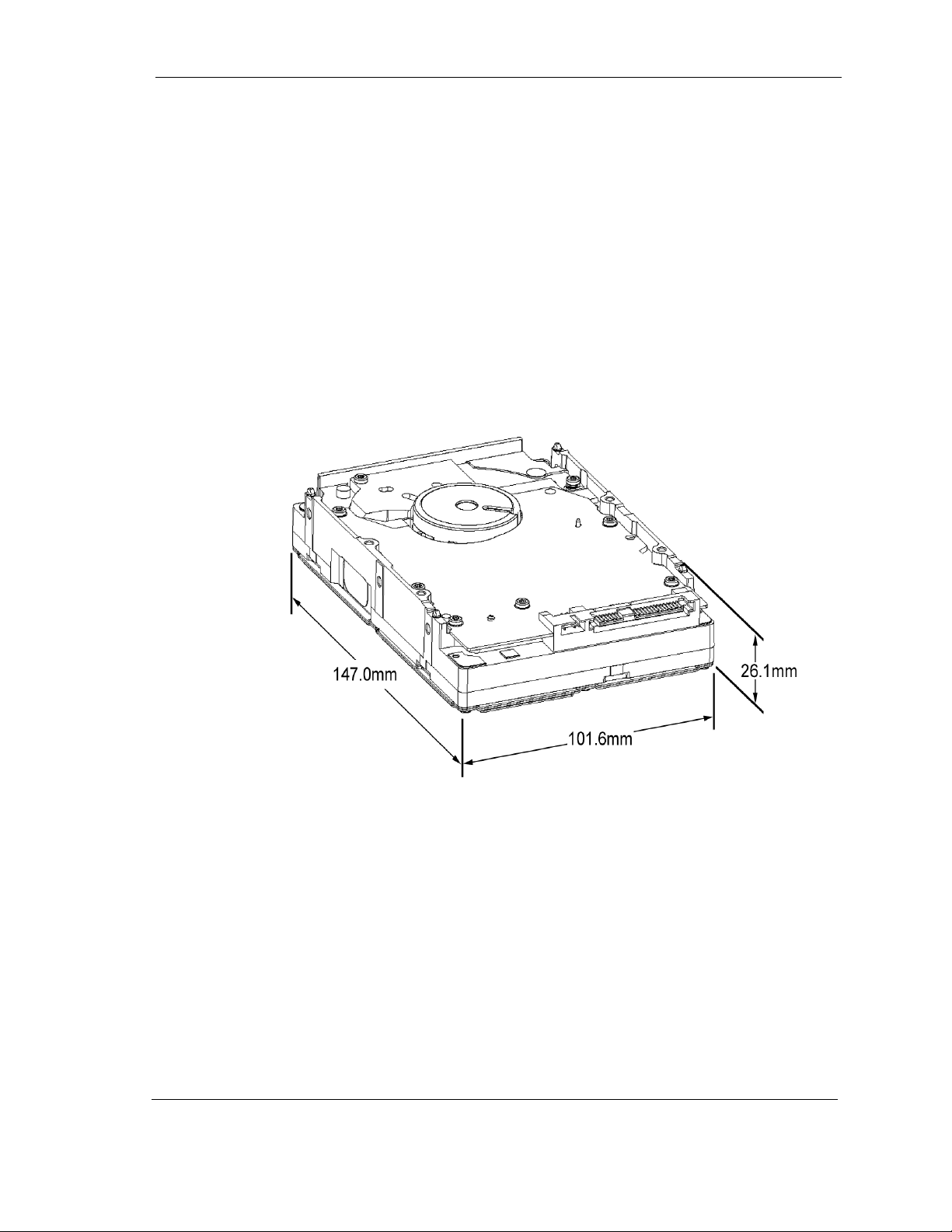
3.2 SPACE REQUIREMENTS
The Maxtor Atlas 10K V hard disk drive is shipped without a faceplate and comes
in the following SCSI interface configurations:
• 68-pin Wide SCSI
• 80-pin SCA-2 SCSI
Figure 3-1 Shows The Mechanical Dimensions of the drives.
Figure 3-1 Dimensions for the Maxtor Atlas 10K V Hard Disk Drives
Maxtor Atlas 10K V 3-3
Page 28

3.2.1 Shock Feet
Maxtor Atlas 10K V hard disk drives are outfitted with plastic shock feet on the
bottom edge of the base casting, near the corners, beneath the side mounting holes
(translucent), and near the corners of the top cover next to the screws (black). The
shock feet give an additional level of isolation to prevent the head and disk damage
that occasionally occurs during unpacking, staging, and installation. The shock feet
attenuate the short-pulse shocks that occur when placing the drive on a hard surface.
If the drive is tested on a hard surface, it should be supported such that the shock
feet are not in contact with a hard surface (the drive should be supported in the
middle, between the shock feet).
Note: To provide optimal protection the shock feet are designed to ex-
ceed the form factor when uncompressed.
3.3 UNPACKING INSTRUCTIONS
CAUTION: The maximum limits for physical shock can be exceeded if
the drive is not handled properly. Special care should be
taken not to bump or drop the drive.
1. Open the shipping container and remove the packing assembly that contains
the drive.
2. Remove the drive from the packing assembly.
CAUTION: During shipment and handling, the antistatic electrostatic dis-
charge (ESD) bag prevents electronic component damage due
to electrostatic discharge. To avoid accidental damage to the
drive, do not use a sharp instrument to open the ESD bag.
Save the packing materials for possible future use.
3. When you are ready to install the drive, remove it from the ESD bag.
3-4 Maxtor Atlas 10K V
Page 29
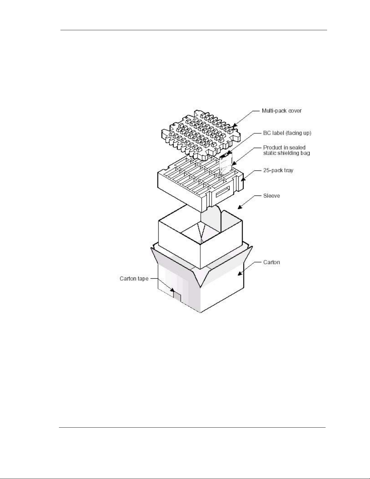
Figure 3-2 shows the packing assembly for a single Maxtor Atlas 10K V hard disk
drive. Shipping containers for 25-pack are available for multiple drive shipments.
Figure 3-2 Drive Packing Assembly
Maxtor Atlas 10K V 3-5
Page 30

3.4 HARDWARE OPTIONS
3.4.1 Configuration Jumpers and Connections
This section includes setup and configuration information for Maxtor Atlas 10K V
drives. These disk drives include
• The 16-bit multimode Ultra320 SCSI, wide version with 68-pin SCSI
connector,
• The 16-bit multimode Ultra320 SCSI, version with SCA-2 80-pin
connector.
Specific individual settings for each drive type are described in Sections 3.5.1
through 3.5.4.
CAUTION: Before you begin, review the Safety, ESD, and Handling precau-
tions described at the beginning of this manual to avoid personal injury or damage to equipment.
3.4.2 Jumper Options on the 68-Pin Wide PCB
This section describes how to configure the jumpers on Maxtor Atlas 10K V disks
with 68-pin SCSI interface connectors. The following features are jumperselectable:
• SCSI ID (0), (1), (2), (3) – SCSI Bus Device Identification
•Delay Spin
• Single-Ended, Disable LVD
• Busy Out (Remote LED)
• Write Protect
•Stagger Spin
Note: The disk drive does not support on-board SCSI termina-
tion.
Note: The configuration of a Maxtor Atlas 10K V hard disk
drive depends on the host system in which it is to be installed. Figure 3-3 shows the printed circuit board (PCB)
assemblies for 68-pin SCSI configurations, indicating the
jumpers that control some of these options.
3-6 Maxtor Atlas 10K V
Page 31

4-Pin Power
Connector
12-Pin Option
Connector
68-pin SCSI
Connector
Figure 3-3 Jumper Locations on the 68-Pin Wide SCSI Drive PCB
Maxtor Atlas 10K V 3-7
Page 32

Table 3-1 SCSI ID Selection on Option Connector (68-Pin SCSI Connector Drives)
SCSI ID
Jumper Location – J3 Option Header
Pin Pair 7/8 Pin Pair 5/6 Pin Pair 3/4 Pin Pair 1/2
00 0 0 0
11 0 0 0
20 1 0 0
31 1 0 0
40 0 1 0
51 0 1 0
60 1 1 0
71 1 1 0
80 0 0 1
91 0 0 1
10 0 1 0 1
11 1 1 0 1
12 0 0 1 1
13 1 0 1 1
14 0 1 1 1
15 1 1 1 1
Note: 0 = No Jumper, 1 = Jumper Installed
Configure the drive for remote (external) SCSI ID selection by removing the SCSI
ID jumpers (if present) from the referenced SCSI ID pins. Then connect the leads
from the external selection switch to the referenced pins. Observe the following
guidelines while doing so:
• ID bit 0, at Pin 8, is the Least Significant Bit.
• SCSI ID bits 0, 1, 2, and 3 (pins 8, 6, 4, and 2, respectively) are active
LOW signals. That is, the bit is a 1 if the corresponding remote switch
is closed to ground or jumper installed.
• Use pins 1, 3, 5 and 7 as the associated ground returns for ID bits 3, 2,
1, and 0, respectively.
3.4.2.1 Write Protection
To configure Write Protection for the drive, install a jumper across pin pair 11/12
on the J3 Option Header. To disable Write Protection on the drive, remove the
jumper.
3-8 Maxtor Atlas 10K V
Page 33

3.4.2.2 Delay Spin (DS), Stagger Spin (SS)
Maxtor Atlas 10K V drives have three Spin Up modes:
Option 1 (No jumpers installed):
Spi n up i mme dia te l y wh en p ow e r is app li e d. V er i fy th at n o jum p er i s ins t all ed
across the Delay Spin pin pair of the J3 Option Header.
Option 2 (Delay Spin jumper installed):
Spin up on START STOP UNIT command: Install the jumper across pin pair
15/16 (GND/Delay Spin) on the J3 Option Header.
3.4.2.3 Single-Ended Operation – Force SE (Disable LVD)
Install a jumper across pin pair 17/18 (SE) on the J3 Option Header to operate the
disk drive as a single-ended device. Remove the SE jumper for LVD operation and
monitoring of the DIFFSENS signal.
3.4.2.4 Remote Busy and Fault Displays
Busy and Fault status of the drive can be monitored remotely by connecting a
remote (external) Busy and/or remote Fault display LEDs.
Remote Fault LED
On the J1 Option Connector, connect the cathode side of the remote Fault LED
to pin 2, Fault LED. Connect the anode side of the LED to pin 11, +5V.
Maxtor Atlas 10K V 3-9
Page 34

3.4.3 SCA-2 80-Pin Connector Versions
This section describes the SCA-2 (Single Connector Attachment) 80-pin connector
for Maxtor Atlas 10K V drives with the following features:
• SCSI ID
•Spin Up
• Activity LED displays
Use Figure 3-4 to locate the appropriate pins for configuring the drive. Note that
Figure 3-4 does not call out each of the 80 pins on the connector, but rather
illustrates the layout of the pins.
Note: The SCA-2 Connector version of the disk drives does not provide
the following jumper configuration: TERMPWR, Active Termination, or Write Protection.
3.4.3.1 Termination for the 80-Pin SCA-2 Connector Versions
CAUTION: These versions of Maxtor Atlas 10K V disk drives cannot be
configured to provide bus termination. Therefore, be sure to
properly terminate the SCSI bus on which this drive is installed.
Note: Refer to your system or SCSI controller documentation regard-
ing any additional recommendations regarding drive placement
on the SCSI bus and SCSI bus termination.
3-10 Maxtor Atlas 10K V
Page 35

3.4.3.2 SCSI ID for SCA-2 Versions
Each SCSI device on the bus must have a unique SCSI ID number assigned to it.
The drive can be configured for SCSI ID numbers that range from 0 through 15.
Configure the SCSI ID by providing the proper open or ground signal inputs to the
referenced pins of the drive’s 80-pin new version SCA-2 connector (Figure 3-4).
Refer to Table 3-2 for SCSI ID pin assignments.
Note: Refer to your system or SCSI controller documentation for spe-
cific recommendations about assigning SCSI ID numbers for
your specific system.
Figure 3-4 Pin Locations on SCA-2 Connector
Maxtor Atlas 10K V 3-11
Page 36

Table 3-2 SCSI ID Pin Assignments (SCA-2 Connector Versions of the Disk Drive)
Location on SCA Connector
SCSI ID
00 0 0 0
10 0 0 1
20 0 1 0
30 0 1 1
40 1 0 0
50 1 0 1
60 1 1 0
70 1 1 1
81 0 0 0
91 0 0 1
10 1 0 1 0
11 1 0 1 1
12 1 1 0 0
13 1 1 0 1
14 1 1 1 0
15 1 1 1 1
ID3 - Pin
80
ID2 - Pin 40 ID1 - Pin 79 ID0 - Pin 39
Note: 0 indicates an open circuit and 1 indicates ground.
3.4.3.3 Spin Up for the 80-Pin SCA-2 Connector Versions
Maxtor Atlas 10K V drives have three Spin Up modes:
Option 1 Spin up occurs immediately when power is applied.
Option 2 Drive spin up occurs after a predetermined delay following power on.
Set the delay parameters with the MODE SELECT Command,
Maxtor (Vendor) Special Function Control Page (39h).The delay is
equal to a user-specified multiplier multiplied by the numerical SCSI
ID of the drive. This will give a staggered spin-up in multiple-drive
installations.
Option 3 Drive spin up is controlled by the START STOP UNIT command.
Configure the desired spin up option (Table 3-3) by setting the state of the
DELAY_SPIN (Pin 38) and STAGGER_SPIN (Pin 78) inputs on the 80-pin SCA2 connector (Figure 3-4). The states of these signals are set by using either hardwired connections at the backplane or backplane logic.
3-12 Maxtor Atlas 10K V
Page 37

Table 3-3 Spin Up on Power On Options
Option
STAGGER_SPIN
(Pin 78)
DELAY_SPIN
(Pin 38)
Option 1 – Spin Up When Power is Applied Open Open
Option 2 – Spin Up After Delay Ground Open
Option 3 – Spin Up on START Command Open Ground
Reserved Ground Ground
3.4.3.4 Activity LED for SCA-2 Connector Versions
The drive provides the output BUSY_OUT signal to power a user-supplied activity
LED.
The output indicates the drive is performing a SCSI operation. To use this output,
connect a user-supplied LED cathode to the BUSY_OUT connection, pin 77 on
the SCA Connector (Figure 3-4). The LED anode must be attached to the proper
+5 VDC supply through an appropriate current-limiting resistor.
Maxtor Atlas 10K V 3-13
Page 38

3.5 INTERFACE CONNECTOR (J1)
The configuration of J1 is different for the 68-pin and 80-pin SCSI variations.
Figure 3-5 shows the various connector styles.
Figure 3-5 J1 Interface Connector Configurations
3-14 Maxtor Atlas 10K V
Page 39

Maxtor Atlas 10K V 3-15
Page 40

3.5.1 68-Pin Wide SCSI Connector - LVD
Table 3-4 68-Pin Wide LVD Pin Assignments
SIGNAL
NAME
CONNECTOR
CONTACT
NUMBER
CABLE CONDUCTOR
NUMBER
CONNECTOR
CONTACT
NUMBER
SIGNAL
NAME
+DB (12) 1 1 2 35 –DB (12)
+DB (13) 2 3 4 36 –DB (13)
+DB (14) 3 5 6 37 –DB (14)
+DB (15) 4 7 8 38 –DB (15)
+DB (P1) 5 9 10 39 –DB (P1)
+DB (0) 6 11 12 40 –DB (0)
+DB (1) 7 13 14 41 –DB (1)
+DB (2) 8 15 16 42 –DB (2)
+DB (3) 9 17 18 43 –DB (3)
+DB (4)10192044–DB (4)
+DB (5)11212245–DB (5)
+DB (6)12232446–DB (6)
+DB (7)13252647–DB (7)
+DB (P)14272848–DB (P)
GROUND 15 29 30 49 GROUND
DIFFSENS 16 31 32 50 GROUND
TERMPWR17333451TERMPWR
TERMPWR18353652TERMPWR
RESERVED 19 37 38 53 RESERVED
GROUND 20 39 40 54 GROUND
+ATN 21 41 42 55 –ATN
GROUND 22 43 44 56 GROUND
+BSY 23 45 46 57 –BSY
+ACK 24 47 48 58 –ACK
+RST 25 49 50 59 –RST
+MSG 26 51 52 60 –MSG
+SEL 27 53 54 61 –SEL
+C/D 28 55 56 62 –C/D
+REQ 29 57 58 63 –REQ
+I/O 30 59 60 64 –I/O
+DB (8)31616265–DB (8)
+DB (9)32636466–DB (9)
+DB (10) 33 65 66 67 –DB (10)
+DB (11) 34 67 68 68 –DB (11)
Note: The conductor number refers to the conductor position when
using 0.635 mm (0.025 inch) centerline flat ribbon cable. Other
cable types may be used to implement equivalent contact assignments.
3.5.1.1 68-Pin Wide Mating Connector
The cable plug connector that mates with the 68-pin hard disk drive connector is
the AMP AMPLIMITE .050 Series III, part number 749925-5.
3-16 Maxtor Atlas 10K V
Page 41

3.5.2 80-Pin SCA-2 SCSI Connector - LVD
Table 3-5 80-Pin SCA-2 LVD Pin Assignments
80-PIN CONNECTOR CONTACT
AND SIGNAL NAME
12V CHARGE 1 NOT
12V 2 12V GROUND 42
CABLE
CONDUCTOR
NUMBER
APPLICABLE
80-PIN CONNECTOR CONTACT
AND SIGNAL NAME
12V GROUND 41
12V 3 12V GROUND 43
12 V 4 MATED 1 44
OPT 3.3 VOLTS 5 OPT 3.3V CHARGE 45
OPT 3.3 VOLTS 6 DIFFSNS 46
- DB (11) 7 +DB (11) 47
- DB (10) 8 +DB (10) 48
- DB (9) 9 +DB (9) 49
- DB (8) 10 +DB (8) 50
- I/O 11 +I/O 51
- REQ 12 +REQ 52
- C/D 13 +C/D 53
- SEL 14 +SEL 54
- MSG 15 +MSG 55
- RST16 +RST56
- ACK 17 +ACK 57
- BSY 18 +BSY 58
- ATN 19 +ATN 59
- DB (P0) 20 +DB (P0) 60
- DB (7) 21 +DB (7) 61
- DB (6) 22 +DB (6) 62
- DB (5) 23 +DB (5) 63
- DB (4) 24 +DB (4) 64
-DB (3) 25 +DB (3) 65
Maxtor Atlas 10K V 3-17
Page 42

–DB (2) 26 NOT
–DB (1) 27 +DB (1) 67
–DB (0) 28 +DB (0) 68
–DB (P1) 29 +DB (P1) 69
–DB (15) 30 +DB (15) 70
–DB (14) 31 +DB (14) 71
–DB (13) 32 +DB (13) 72
–DB (12) 33 +DB (12) 73
5V 34 MATED 2 74
5V 35 5V GROUND 75
5V CHARGE 36 5V GROUND 76
SPINDLE SYNC 37 ACTIVE LED OUT 77
RMT START 38 DLYD_START 78
SCSI ID (0) 39 SCSI ID (1) 79
SCSI ID (2) 40 SCSI ID (3) 80
3.5.2.1 80-Pin SCA-2 Mating Connectors
APPLICABLE
The compatible 80-pin mating connectors are:
• Right-angle receptacle, AMP CHAMP, .050 Series I, part number 787535-1.
• Vertical receptacle, AMP CHAMP .050 Series I, part number 787311-2.
• Vertical receptacle, BERG part number 71780-001.
+DB (2) 66
3-18 Maxtor Atlas 10K V
Page 43

3.5.3 68-Pin Wide Single-Ended SCSI Connector
Table 3-6 68-Pin Wide Single-Ended Pin Assignments
SIGNAL
NAME
CONNECTOR
CONTACT
NUMBER
CABLE CONDUCTOR
NUMBER
CONNECTOR
CONTACT
NUMBER
SIGNAL
NAME
GROUND 1 1 2 35 –DB (12)
GROUND 2 3 4 36 –DB (13)
GROUND 3 5 6 37 –DB (14)
GROUND 4 7 8 38 –DB (15)
GROUND 5 9 10 39 –DB (P1)
GROUND 6 11 12 40 –DB (0)
GROUND 7 13 14 41 –DB (1)
GROUND 8 15 16 42 –DB (2)
GROUND 9 17 18 43 –DB (3)
GROUND 10 19 20 44 –DB (4)
GROUND 11 21 22 45 –DB (5)
GROUND 12 23 24 46 –DB (6)
GROUND 13 25 26 47 –DB (7)
GROUND 14 27 28 48 –DB (P)
GROUND 15 29 30 49 GROUND
GROUND 16 31 32 50 GROUND
RESERVED 19 37 38 53 RESERVED
GROUND 20 39 40 54 GROUND
GROUND 21 41 42 55 –ATN
GROUND 22 43 44 56 GROUND
GROUND 23 45 46 57 –BSY
GROUND 24 47 48 58 –ACK
GROUND 25 49 50 59 –RST
GROUND 26 51 52 60 –MSG
GROUND 27 53 54 61 –SEL
GROUND 28 55 56 62 –C/D
GROUND 29 57 58 63 –REQ
GROUND 30 59 60 64 –I/O
GROUND 31 61 62 65 –DB (8)
GROUND 32 63 64 66 –DB (9)
GROUND 33 65 66 67 –DB (10)
GROUND 34 67 68 68 –DB (11)
Note:
1. The minus sign next to a signal indicates active low.
2. The conductor number refers to the conductor position when using 0.635
mm (0.025 inch) centerline flat ribbon cable. Other cable types may be used
to implement equivalent contact assignments.
Maxtor Atlas 10K V 3-19
Page 44

3.5.4 80-Pin SCA-2 Single-Ended SCSI Connector
Table 3-7 80-Pin SCA-2 Single-Ended Pin Assignments
80-PIN CONNECTOR CONTACT
AND SIGNAL NAME
12V CHARGE 1 NOT APPLICABLE 12V GROUND 41
12V 2 12V GROUND 42
12V 3 12V GROUND 43
12 V 4 MATED 1 44
OPT 3.3 VOLTS 5 OPT 3.3V CHARGE 45
OPT 3.3 VOLTS 6 GROUND 46
–DB (11) 7 GROUND 47
–DB (10) 8 GROUND 48
–DB (9) 9 GROUND 49
–DB (8) 10 GROUND 50
–I/O 11 GROUND 51
–REQ 12 GROUND 52
–C/D 13 GROUND 53
–SEL 14 GROUND 54
–MSG 15 GROUND 55
–RST 16 GROUND 56
–ACK 17 GROUND 57
–BSY 18 GROUND 58
–ATN 19 GROUND 59
–DB (P0) 20 GROUND 60
–DB (7) 21 GROUND 61
–DB (6) 22 GROUND 62
–DB (5) 23 GROUND 63
–DB (4) 24 GROUND 64
–DB (3) 25 GROUND 65
–DB (2) 26 GROUND 66
–DB (1) 27 GROUND 67
–DB (0) 28 GROUND 68
–DB (P1) 29 GROUND 69
–DB (15) 30 GROUND 70
–DB (14) 31 GROUND 71
–DB (13) 32 GROUND 72
–DB (12) 33 GROUND 1
5V 34 MATED 2 74
5V 35 5V GROUND 75
5V CHARGE 36 5V GROUND 76
SPINDLE SYNC 37 ACTIVE LED OUT 77
RMT START 38 DLYD_START 78
SCSI ID (0) 39 SCSI ID (1) 79
SCSI ID (2) 40 SCSI ID (3) 80
CABLE
CONDUCTOR
NUMBER
80-PIN CONNECTOR CONTACT
AND SIGNAL NAME
3-20 Maxtor Atlas 10K V
Page 45

3.6 DRIVE MOUNTING AND INSTALLATION
Drive mounting orientation, clearance, and ventilation requirements are described
in the following subsections.
3.6.1 Orientation
The mounting holes on the Maxtor Atlas 10K V hard disk drive allow the drive to
be mounted in any orientation. Figure 3-6 shows the location of the three
mounting holes on each side of the drive. The drives also can be mounted using the
four mounting hole locations on the PCB side.
All dimensions are in millimeters. For mounting, #6-32 UNC screws are
recommended.
Figure 3-6 Mounting Dimensions Maxtor Atlas 10K V Drives
Maxtor Atlas 10K V 3-21
Page 46

3.6.2 Mounting Screw Clearance
The printed-circuit board assembly (PCBA) is very close to the mounting holes.
Figure 3-7 specifies the clearance between the screws in the mounting holes and the
PCBA. Do not use mounting screws longer than the maximum lengths specified in
Figure 3-7. The specified screw length allows full use of the mounting-hole threads,
while avoiding damaging or placing unwanted stress on the PCBA. Clearance from
the drive to any other surface (except mounting surfaces) must be a minimum of
1.25 mm (0.05 inches).
Figure 3-7 Mounting Screw Clearance for Maxtor Atlas 10K V Drive
CAUTION: The PCB is very close to the mounting holes. Do not exceed the speci-
fied length for the mounting screws. The specified screw length allows full
use of the mounting-hole threads, while avoiding damaging or placing
unwanted stress on the PCB.
Figure 3-7 specifies the minimum clearance between the PCB and the
screws in the mounting holes. The maximum torque applied to the
screws must not exceed 8.6 inch-pounds.
3-22 Maxtor Atlas 10K V
Page 47

3.6.3 Mounting
For the best results during performance benchmark testing, it is highly
recommended that the drive be mounted firmly in a system or fixture, rather than
sitting unconstrained on a tabletop. If it is necessary to do early testing of the drive
while it is unconstrained, the drive should rest on a flat, smooth, semi-cushioned
surface (similar to a mousepad). The drive should not be operated on a hard
surface—this avoids performance degradations due to the higher incidence of
recovered errors.
3.6.4 Ventilation
The Maxtor Atlas 10K V hard disk drive may operate with or without a cooling fan
provided that the maximum HDA temperature as measured on the drives’s top
cover does not exceed 131×F (60×C). Drive reliability and warranty will be limited
if the drive is exposed to temperatures greater than 60×C. Figures 3-8 and 3-9 show
airflow recommended for adequate cooling. Clearance from the drive to any other
surface above and below the drive must be a minimum of 1.25mm (1/16 inch).
Maxtor leaves the design and application of cooling and clearance for the disk drive
to the User, but the drive must maintain a case temperature at or below 60×C.
Above Unit
Below Unit
Figure 3-8 Lengthwise Airflow Cooling
Maxtor Atlas 10K V 3-23
Page 48

Above Unit
Below Unit
Figure 3-9 Crosswise Airflow Cooling
3-24 Maxtor Atlas 10K V
Page 49

This chapter gives a detailed description of the physical, electrical, and environmental
characteristics of the Maxtor Atlas 10K V hard disk drives.
4.1 SPECIFICATION SUMMARY
Table 4-1 Specifications
Chapter 4
SPECIFICATIONS
MAXTOR
DESCRIPTION
Non-RoHS Model Numbers:
RoHS Model Numbers:
Formatted Capacity 73.5 GB 147.1 GB 300 GB
Nominal rotational speed (rpm) 10,000 10,000 10,000
Number of Disks 1 2 4
Number of R/W heads 2 4 8
Data Organization:
Maximum BPI 732K 732K 732K
Zones per surface 16 16 16
Track density 102,000 TPI 102,000 TPI 102,000 TPI
User Data Cylinders 81,782 81,782 81,782
Sectors per track:
Inside zone 624 624 624
Outside zone 1114 1114 1114
Total User Sectors 143,666,191 287,332,383 585,937,500
Bytes per sector 512 - 524 512 - 524 512 - 524
Recording technology PRML PRML PRML
Maximum linear density 678 fci 678 fci 678 fci
ATLAS 10K V
73.5 GB
8D073J0
8D073L0
8J073J0
8J073L0
MAXTOR
ATLAS 10K V
147.1 GB
8D147J0
8D147L0
8J147J0
8J147L0
MAXTOR
ATLAS 10K V
300 GB
8D300J0
8D300L0
8J300J0
8J300L0
Maxtor Atlas 10K V 4-1
Page 50

DESCRIPTION
MAXTOR
ATLAS 10K V
73.5 GB
MAXTOR
ATLAS 10K V
147.1 GB
MAXTOR
ATLAS 10K V
300 GB
Maximum effective areal
density 75 Gbits/in
2
75 Gbits/in
2
75 Gbits/in
2
Servo Mechanical Timing Specifications:
Sequential Head Switch Time
Sequential Cylinder Switch Time
Random
Random
Full Stroke
4
Average Seek (Read) 4.0 ms typical 4.2 ms typical 4.4 ms typical
4
Average Seek (Write) 4.5 ms typical 4.7 ms typical 4.9 ms typical
5
Seek (Read) 11.0 ms
SCSI ‘Hard’ Reset Time
Power on to Drive Ready
2
0.3 ms read
0.5 ms write
3
0.3 ms read
0.5 ms write
typical
6
22 ms typical
25 sec
maximum
7
25 sec typical 25 sec typical 25 sec typical
0.3 ms read
0.5 ms write
0.3 ms read
0.5 ms write
11.0 ms
typical
22 ms typical
25 sec
maximum
0.3 ms read
0.5 ms write
0.3 ms read
0.5 ms write
11.0 ms
typical
22 ms typical
25 sec
maximum
Data transfer Rates:
Sequential Throughput
Read/Write
89 MB/s
maximum
89 MB/s
maximum
89 MB/s
maximum
Buffer Size 8 MB 8 MB 8 MB
Reliability:
Seek error rate
8
Unrecoverable error rate
Error correction method
(with cross check)
<10 in 10
8
<1 in 10
48 Bytes
Reed-Solomon
with XCHK
8
15
<10 in 10
<1 in 10
48 Bytes
Reed-Solomon
with XCHK
8
15
<10 in 10
<1 in 10
8
15
48 Bytes
Reed-Solomon
with XCHK
Contact Start/Stop Cycles 50,000 min. 50,000 min. 50,000 min.
Auto head-park method Magnetic Latch Magnetic Latch Magnetic Latch
Note: Seek time is defined as the time required for the actuator to seek
to a new position and settle on a track. It is measured by averaging the execution time of a minimum of 1000 operations of the
indicated type as shown in Table 4-1. The seek times include
head settling time, but do not include command overhead time,
time spent reading or writing data, or rotational latency delays.
Unless otherwise specified, read/seek command settling criteria
is assumed.
4-2 Maxtor Atlas 10K V
Page 51

1. Typical specifications assume 25°C ambient temperature, nominal supply
voltages and no applied shock or vibration.
Maximum specifications assume worst case extremes of operating temperature,
humidity, and supply voltages.
2. Sequential Head Switch time is the time from the conclusion of the last
sector of a track to the beginning of the first logical sector on the next track
of the same cylinder. It includes sequencer overhead for write setup on head
and cylinder switch.
3. Sequential Cylinder Switch time is the time from the conclusion of the last
sector of a cylinder to the first logical sector on the next cylinder. It includes
sequencer overhead for write setup on head and cylinder switch.
4. Random LBA.
5. Full Stroke seek is defined as a seek from cylinder 0 to maximum cylinder
or vice versa. It may include one head switch.
6. SCSI ‘Hard’ Reset time is the time from Reset to Selection.
7. At power on start-up error algorithms are used. These recovery routines
may extend the time to Drive Ready by as much as 30 seconds.
8. Refer to Section 4.11, “DISK ERRORS” for details on error rate
definitions.
4.2 FORMATTED CAPACITY
At the factory, the Maxtor Atlas 10K V receives a low-level format that creates
the actual tracks and sectors on the drive. Table 4-2 shows the capacity resulting
from this process. Formatting done at the user level for operation with DOS,
UNIX, or other operating systems, will result in less capacity than the physical
capacity shown.
Table 4-2 Formatted Capacity
MAXTOR
ATLAS 10K V
73.5 GB
Formatted Capacity 73.5 GB 147.1 GB 300 GB
Number of 514-524
byte
sectors available
512 byte Sectors 143,666,191 287,332,383 585,937,500
139,463,602 279,041,740 566,793,894
MAXTOR
ATLAS 10K V
147.1 GB
MAXTOR
ATLAS 10K V
300 GB
Maxtor Atlas 10K V 4-3
Page 52

4.3 DATA TRANSFER RATES
Data is transferred from the disk to the read buffer at a rate of up to 89 MB/s in
bursts. Data is transferred from the read buffer to the SCSI bus at a rate of up to
6 MB/s in the asynchronous mode, or at up to 320 MB/s in the synchronous
mode. For more detailed information on interface timing, refer to Chapter 6.
4.4 TIMING SPECIFICATIONS
Table 4-3 illustrates the timing specifications of the Maxtor Atlas 10K V hard disk
drive.
Table 4-3 Timing Specifications for Maxtor Atlas 10K V
PARAMETER
Sequential Head Switch Time
Sequential Cylinder Switch Time
Random Average Seek (Read)
Random Average Seek (Write)
Average Rotational Latency 3 ms 3 ms
1/3 Stroke Seek (Read)
Full-Stroke Seek
SCSI “Hard Reset Time”
Power On to Dr ive Re ady
Power On to Selection 2.5 seconds 3 seconds
2
3
4
4
5
6
7
8
MAXTOR ATLAS 10K V 73.5/147.1/300 GB
TYPICAL NOMINAL
0.3 ms typical (read)
0.5 ms typical (write)
0.3 ms typical (read)
0.5 ms typical (write)
<4.0/ 4.2 / 4.4 ms 4.8 ms
4.5 / 4.7/ 4.9 ms 5.3 ms
<3 ms 4.5 ms
11.0 ms 12.0 ms
20 ms 20 ms
25 seconds 30 seconds
1
MAXIMUM
1. Typical specifications assume 25°C ambient temperature, nominal supply
voltages, and no applied shock or vibration. Maximum specifications
assume worst case extremes of operating temperature, humidity, and
supply voltages.
2. Sequential Head Switch Time is the time from the conclusion of the last
sector of a track to the beginning of the first logical sector on the next
track of the same cylinder.
3. Sequential Cylinder Switch Time is the time from the conclusion of the
last sector of a cylinder to the first logical sector on the next cylinder.
4. Random LBA.
5. 1/3 Stroke Seek is defined as any seek of maximum length cylinder/3. 1/
3 stroke seek may include one head switch.
6. Full Stroke Seek is defined as a seek from cylinder 0 to maximum cylinder
or vice versa. Full stroke may include one head switch.
7. SCSI “Hard Reset Time” is the time from Reset to Selection.
1
N/A
N/A
4-4 Maxtor Atlas 10K V
Page 53

8. At power on start up error algorithms are used and may extend the time to
Drive Ready to as long as 30 seconds.
4.5 POWER
The Maxtor Atlas 10K V hard disk drive operates from two supply voltages:
+12 V +/-10% @ Spin up, +/- 5% While running
+5 V +/- 5%
Allowable ripple and noise for each voltage:
+12 V 800 mV p-p (100 Hz to 8 KHz)
+5 V 250 mV p-p (100 Hz to 20MHz)
4.5.1 Power Sequencing
MAXTOR ATLAS 10K IV 73.5/147.1/300 GB
450 mV p-p (8 KHz to 20 KHz)
250 mVp-p (20KHz - 20MHz)
You may apply the power in any order or manner, or open either the power or
power return line with no loss of data or damage to the disk drive. However,
data may be lost in the sector being written at the time of power loss. The drive
can withstand transient voltages of +10% to –10% from nominal while powering
up or down.
4.5.2 Power Reset Limits
When powering up, the drive remains reset (inactive) until both rising Voltage
thresholds reset limits are exceeded for 100 ms. When powering down, the drive
resets immediately when either supply voltage drops below the falling voltage
threshold.
Table 4-4 Power Reset Limits
DC VOLTAGE THRESHOLD
+5 V 4.31/4.43v
+12 V 9.59/9.77v
1
Maxtor Atlas 10K V 4-5
Page 54

4.5.3 Drive Power Dissipation
Table 4-5 lists the drive power dissipation and the corresponding currents for the
various modes of operation of the Maxtor Atlas 10K V hard disk drive.
Table 4-5 Power Dissipation in Various Modes (Low-Profile Drives)
+5V
147.1
GB
1, 4
300 GB 73.5 GB
TYPICAL AVG.
POWER5 (WATTS)
147.1
GB
TYPICAL AVERAGE CURRENT
(AMP RMS UNLESS OTHERWISE NOTED)
MODE OF
OPERATION
73.5 GB
Startup
peak1 1.34 1.33 1.57 0.84 0.68 0.69 19.7 19.4 22.41
Idle2 0.33 0.38 0.56 0.81 0.77 0.80 8.01 8.52 10.77
Max Work 0.75 0.78 0.96 0.84 0.80 0.83 13.16 13.32 15.70
+12V
147.1
GB
300 GB 73.5 GB
Note:
1. Current is RMS except for Startup. Startup current is the peak (> 10 ms)
current required during spindle startup. Current measurements do not
include power required for SCSI termination.
2. Idle mode is in effect when the drive is not reading, writing, seeking, or
executing any commands. A portion of the R/W circuitry is powered
down, the motor is up to speed and the Drive Ready condition exists.
3. Max Workload: Maximum workload is defined as a random read/write
profile with a 50% read and 50% write distribution. The transfer length is 8
blocks (4KB), and a queue depth of 4 is used.
4. Power requirements reflect nominal values for +12V and +5V power
supplies.
300 GB
4-6 Maxtor Atlas 10K V
Page 55

4.6 ACOUSTICS
Table 4-6 specifies the acoustical characteristics of the Maxtor Atlas 10K V hard
disk drive. The acoustics is measured in an anechoic chamber with background
noise <25 dBA.
Table 4-6 Acoustical Characteristics—Sound Power per ISO 7779
OPERATING MODE
Idle On Track
73.5 GB
147.1 GB
300 GB
Seeking Random
73.5 GB
147.1 GB
300 GB
1. The specifications for idle and operating acoustic noise as per ISO Standard
7779, “Engineering Methods for Free Field Conditions Over a Reflecting
PLane.” All specifications are sound power level maximum limits, Aweighted, referred to 1 picowatt as indicated in the standard. The drive will
be mounted for the test in the manufacturer’s defined nominal position.
The unit under test should be supported so that its bottom surface in the test
orientation is less than or equal to 6 centimeters from the chamber floor, but
not in contact with it. The unit should be supported with small, compliant,
well-damped blocks that rest on the floor.
SOUND POWER
(MEAN)
MAXTOR ATLAS 10K IV 73.5/147.1/300 GB
3.16
3.52
3.67
3.60
3.87
3.96
SOUND POWER
(MEAN + 3 SIGMA)
3.38
3.68
3.91
3.72
4.04
4.19
2. The relationship between bels and dBA for sound power is 1 bel = 10dBA.
4.6.1 Acoustic Toned Quality
A typical drive will have no discrete tones that exceeds a tone ratio of 8dB as
measured per ECMA 74,8
th
Edition, December 2003.
Maxtor Atlas 10K V 4-7
Page 56

4.7 MECHANICAL
The Maxtor Atlas 10K V hard disk drives have the following mechanical
characteristics:
1
Height
: 1.028 in. (26.1 mm)
Width: 4.0 in. (101.6 mm)
Depth: 5.787 in. (147.0mm)
Weight (4-disk): 1.8 Ib (820 grams)
All dimensions are exclusive of any optional faceplate.
Drive mode small form factor specifications.
1. Except when shock feet are uncompressed (see of Chapter 3).
4.8 ENVIRONMENTAL CONDITIONS
Table 4-7 summarizes the environmental specifications of the Maxtor Atlas 10K
V hard disk drive.
Table 4-7 Environmental Specifications
PARAMETER OPERATING NON-OPERATING
Te m p e r a t u r e
(Non-condensing)
Maximum HDA Temperature 60
Temperature Gradient
(Non-condensing)
Humidity
Maximum Wet Bulb
Te m p e r a t u r e
Humidity Gradient 30% per hour 30%per hour
Altitude
1
2
5
° to 55°C
(41° to 131
°F)
-40
(-40
°CN/A
20°C/hr maximum 30°C/hr maximum
5% to 95% RH
32°C (89.6°F)
-300 m to 3,048 m
(-1,000 to 10,000 ft.)
5% to 95% RH
46°C (114°F)
-300 m to 12,000 m
(-1,000 to 40,000 ft.)
1. No condensation.
2. Altitude is relative to sea level. 1,000 feet = 305 meters.
1.
° to 70°C
° to 158°F)
4-8 Maxtor Atlas 10K V
Page 57

4.9 ELECTROMAGNETIC CONDITIONS
4.9.1 EMI/RFI Susceptibility
3 Volts/meter 80% modulated from 80 to 1000 MHz.
4.9.2 ESD
Drive must function with no data loss or component damage with air discharges
of 1 to 15 KV, and contact discharges of 2 to 8 KV in both positive and negative
voltages.
4.9.3 Sensitivity to Magnetic Fields
The Maxtor Atlas family of drives meet 3A @ 230V / 50 Hz specification.
4.10 SHOCK AND VIBRATION
The Maxtor Atlas 10K V hard disk drive can withstand levels of shock and
vibration applied to any of its three mutually perpendicular axes, or principal base
axis, as specified in Table 4-8. A functioning drive can be subjected to specified
operating levels of shock and vibration. When a drive has been subjected to
specified non-operating levels of shock and vibration, with power to the drive
off, there will be no change in performance at power on.
When packed in its 1-pack shipping container, the Maxtor Atlas 10K V drive can
withstand a drop from 42 inches onto a concrete surface on any of its surfaces,
six edges, or three corners. The 20-pack shipping container can withstand a drop
from 36 inches onto a concrete surface on any of its surfaces, six edges, or three
corners.
Table 4-8 Shock and Vibration Specifications
PARAMETER OPERATING NON-OPERATING
Shock linear Half Sine
1
2 msec
Read/Write
Shock linear Half Sine
11 msec
Shock rotational
(rad/s
Vibration Swept
Vibration Random
(G
2
/Hz)
1
2)1
, 2 msec
1
63G/30G
15 G
7000 25,000
1.5G 0-p 5-500 Hz
0.008 10—300 Hz
0.0012 300—500 Hz
1
1
1
250 G
1
100 G
2.0G 0-p 5–500 Hz
0.014 10—300 Hz
0.01 300—500 Hz
Note: 1. At ambient temperature and no unrecoverable errors.
Maxtor Atlas 10K V 4-9
Page 58

4.11 RELIABILITY
Component Life: 5 years
Preventive Maintenance (PM): Not required
Contact Start/Stop: 50,000 cycles at ambient,
35,000 at Environments
Annualized Failure Rate (AFR) No greater than 0.58 percent
Drive reliability is closely related to the temperatures the drive is exposed to. The
AFR is based on an operational design temperature ambient of 86° F (30° C)
4.12 DISK ERRORS
Table 4-9 provides the error rates for the Maxtor Atlas 10K V hard disk drive.
ERROR TYPE MAXIMUM NUMBER OF ERRORS
Table 4-9 Error Rates
Recovered read errors
Uncorrectable read errors
1. Recovered read errors are errors which require retries for data correction.
Errors corrected by ECC on-the-fly are not considered recovered read
errors. Read on arrival is disabled to meet this specification.
2. Uncorrectable read errors are those that are not correctable using an Error
Correcting Code (ECC), or retries within the retry limits specified in the
mode pages. The drive terminates the command either when a repeating
error pattern occurs, or after both the specified number of retries and
application of triple burst error correction fail to correct the error.
3. A seek error occurs when the actuator fails to reach or remain on the
requested cylinder, and/or the drive requires the execution of the full
calibration routine to locate the requested cylinder.
1
2
<10 events per 1012 bits read
1 event per 10
15
bits read
4-10 Maxtor Atlas 10K V
Page 59

SCSI Description
This chapter contains an overview of SCSI command and status processing and a
detailed description of the commands supported by the disk drives. The SCSI
command system enables the initiator to instruct the drive to perform specific
functions.
In this manual, unless otherwise stated, numerical values are given in decimal.
Hexadecimal numbers, such as opcodes, are always given with an “h” following, as in
5Ah except when entire data tables are in hexadecimal.
5.1 Overview of the SCSI Command Descriptions
The disk drives support the SCSI-3 commands listed in Table 5-1. The command
categories are sequential, normal, and immediate.
Immediate commands are processed when received by the drive. In most cases, these
commands do not require drive resources, do not change the state of the drive, and
bypass the command queue (unless the command is tagged).
Chapter 5
Sequential commands execute in the order that they arrive (unless accompanied by
a HEAD OF QUEUE tag) and execute to completion before a subsequent command
is activated.
Normal commands are allowed to execute concurrently (with the restriction that the
drive executes overlapping writes in the order received). Normal commands are
usually I/O commands
Table 5-1 Supported SCSI Commands
Command Operation Code Category
CHANGE DEFINITION 40h Sequential
FORMAT UNIT 04h Sequential
INQUIRY 12h Immediate
LOG SELECT 4Ch Sequential
LOG SENSE 4Dh Sequential
MODE SELECT (6) 15h Sequential
MODE SELECT (10) 55h Sequential
MODE SENSE (6) 1Ah Sequential
MODE SENSE (10) 5Ah Sequential
PERSISTENT RESERVATION IN 5Eh Sequential
Maxtor Atlas 10K V 5-1
Page 60

Command Operation Code Category
PERSISTENT RESERVATION OUT 5Fh Sequential
READ (6) 08h Normal
READ (10) 28h Normal
READ BUFFER 3Ch Sequential
READ CAPACITY 25h Immediate
READ DEFECT DATA (10) 37h Sequential
READ DEFECT DATA (12) B7h Sequential
READ LONG 3Eh Sequential
REASSIGN BLOCKS 07h Sequential
RECEIVE DIAGNOSTIC RESULTS 1Ch Sequential
RELEASE 17h Sequential
RELEASE (10) 57h Sequential
REPORT LUNS A0h Sequential
REPORT DEVICE IDENTIFIER A3h Sequential
REQUEST SENSE 03h Immediate
RESERVE 16h Sequential
RESERVE (10) 56h Sequential
REZERO UNIT 01h Sequential
SEEK (6) 0Bh Sequential
SEEK (10) 2Bh Sequential
SEND DIAGNOSTIC 1Dh Sequential
SET DEVICE IDENTIFIER A4h Sequential
START STOP UNIT 1Bh Sequential
SYNCHRONIZE CACHE 35h Sequential
TEST UNIT READY 00h Immediate
VERIFY 2Fh Normal
WRITE (6) 0Ah Normal
WRITE (10) 2Ah Normal
WRITE AND VERIFY 2Eh Normal
WRITE BUFFER 3Bh Sequential
WRITE LONG 3Fh Sequential
WRITE SAME 41h Sequential
5-2 Maxtor Atlas 10K V
Page 61

1. Relative Addressing is not supported by the drive. Therefore, in all I/O commands,
the RelAdr bit must be 0.
2. RESERVE and RELEASE are supported, as are third-party reservations. Extent
reservations are not supported.
3. The RECEIVE DIAGNOSTIC RESULTS and SEND DIAGNOSTIC DATA
commands implement vendor-unique pages to test the drive during the
manufacturing process. It is recommended that initiators specify only the non-page
format variants of these commands (PF=0), except for page 0x40.
Maxtor Atlas 10K V 5-3
Page 62

5.2 Command Descriptor Block
An initiator communicates with the drive by sending a 6-, 10-, or 12-byte Command
Descriptor Block (CDB) that contains the parameters for the specific command. The
SCSI command's operation code is always the first byte in the CDB and a control field
is the last byte. For some commands, the CDB is accompanied by a list of parameters
sent during the data-out buffer transfer. Table 5-2 shows the format of a typical sixbyte CDB.
Table 5-2 Typical (6-Byte) Command Descriptor Block-Data Format
Bit
Byte
0 Operation Code
1 Reserved
2 - 3
4 Transfer Length, Parameter List Length, or Allocation Length
5 Control
Note: Reserved fields in CDBs and Parameters have a value of 0; Re-
Table 5-3 contains a description of the CDB fields.
Table 5-4 describes the data format for a typical CDB.
7654321 0
served fields in states and other parameters sent to an initiator are
set to 0.
(MSB)
Logical Block Address
(LBA)
Logical Block Address
(LBA)
Table 5-3 Command Descriptor Block-Field Descriptions
Field Description
Operation Code The first byte of a SCSI CDB contains an operation code. The operation code of the CDB has
a Group Code field (bits 7-5) and a Command Code field (bits 4-0). The 3-bit Group Code field
provides for eight groups of command codes. The 5-bit Command Code field provides for 32
command codes in each group. A total, therefore, of 256 possible operation codes exist. Operation codes are defined in the SCSI command standards. The group code for CDBs specified
therein correspond to the length of the command descriptor as below:
Group Code
0 6-byte commands
1 10-byte commands
2 10-byte commands
3Reserved
4 16-byte commands
5 12-byte commands
6 Vendor specific
7 Vendor specific
The operation code specifies the command being requested. The list of supported SCSI commands and their operation codes are contained in Table 5-1.
Meaning
5-4 Maxtor Atlas 10K V
Page 63

Field Description
Logical Block Address The 6-byte READ, SEEK, and WRITE Command Descriptor Blocks contain a 21-bit Logical
Transfer Length The transfer length field normally specifies the number of sectors to be transferred between the
Parameter List Length The Parameter List Length is used to specify the number of bytes sent during the data-out buffer
Allocation Length The Allocation Length field specifies the maximum number of bytes that the initiator has allo-
Block Address. The 10-, 12-, and 16- Command Descriptor Blocks contain a 32-bit Logical
Block Address.
Commands that require additional parameter data specify the length of the Logical Block Address that is needed. See the specific command descriptions for more detailed information.
Relative Addressing indicates a technique used to determine the next Logical Block Address to
be operated on. The drive does not support Relative Addressing, it defaults to a value of 0,
which specifies that the Logical Block Address specifies the first logical block of a range of logical
blocks to be operated on by the command.
initiator and the drive. For several commands, the transfer length indicates the number of bytes
(not sectors) to be sent. For these commands, this field may be identified by a different name
Commands that use one byte for the transfer length value allow up to 256 sectors of data to be
transferred by one command. A transfer length value of 0 indicates that 256 sectors are to be
sent. Transfer length values of 1 through 255 indicate the number of sectors to be transferred.
Commands that use multiple bytes for the transfer length value function differently. A transfer
length value of 0 indicates that no data transfer is to occur. Transfer length values of 1 or greater
indicate the number of sectors to be transferred.
transfer. This field is typically used for parameters that are sent to a drive (for example, mode,
diagnostic, and log parameters). A parameter list length of 0 indicates that no data is to be transferred.
cated for returned data. The Allocation Length is used to limit the amount of data returned to
the initiator.
An Allocation Length of 0 indicates that no data is to be transferred from the drive to the initiator. The drive terminates the data-in buffer transfer when the specified number of bytes have
been transferred to the initiator or when all available data has been transferred, whichever is less.
Control Field The Control Field is the last byte of every Command Descriptor Block; its format is shown in
Figure 5-2 and described in Table 5-3.
Table 5-4 Typical (6-Byte) Command Descriptor Block - Data Format
Bit
76543210
Byte
5 Vendor Specific Reserved NACA Flag Link
Maxtor Atlas 10K V 5-5
Page 64

Table 5-5 contains a description of the CDB control field.
Table 5-5 Command Descriptor Block Control Field-Field Descriptions
Field Description
Vendor Specific Bits These bits must be 0.
NACA Normal Auto-Contingent Allegiance - This bit must be zero to indicate that
Link Bit A Link bit set to one signals that the initiator requests continuation of a task
Flag Bit The Flag bit is used in conjunction with the Link Bit to notify the initiator in
SCSI-2 Contingent Allegiance rules apply.
(I/O Process) across two or more SCSI commands. If the Link bit is one and the
flag bit is zero, and the command completes successfully, the drive will continue
the task and return a status of INTERMEDIATE and a service response of
Linked Command Complete.
If the Link bit and the Flag bit of the Control word are both set to one, and the
drive completes a command with a status of INTERMEDIATE, the drive will
return a service response of Linked Command Complete (with Flag). Refer to
Section 5.4 for Linked Commands description.
an expedient manner that a command has been completed. Aflag bit set to 1 is
valid only when the Link Bit is set to 1.
5-6 Maxtor Atlas 10K V
Page 65

5.3 Status/Error Reporting
SCSI message-level errors are communicated by messages that are defined specifically
for that purpose. SCSI command-level errors are communicated by a status that is
returned by the drive during the STATUS phase. This phase occurs at the end of each
command, unless the command is terminated by one of the following events:
• ABORT TASK SET message
•ABORT TASK message
• TARGET RESET message
•CLEAR QUEUE message
• Unexpected disconnect
The status code is contained in bits 1 through 5 of the status byte. Bits 0, 6, and 7 are
reserved. Table 5-6 describes the status codes returned by the drive.
Table 5-6 Status Codes
Status Definition Meaning
00h GOOD The drive successfully completed the command.
02h CHECK CONDITION An Auto Contingent Allegiance (ACA) condition occurred.
The drive cannot service the command at the moment, and its Command Descriptor Block has been discarded. The initiator can retry the
command at a later time. This status is returned when:
08h BUSY
10h INTERMEDIATE
18h RESERVATION CONFLICT
28h TASK SET FULL
5.4 Linked Commands
An I/O Process (task) may contain multiple commands that are linked together. The
initiator communicates this condition of linked (or unlinked) commands by setting (or
clearing) the Link bit of the Command Descriptor Block’s control word. A linked
• A non-tagged command is received and the logical unit's command queue is full (all internal command buffers are in use).
• A disconnect privilege was not granted in the IDENTIFY message of a queue-tagged I/O process (Parallel SCSI).
• A disconnect privilege was not granted in the IDENTIFY message of a non-tagged I/O process and a command from another
initiator is currently active (Parallel SCSI)
• A command is received while an auto-contingent allegiance
condition exists for another initiator.
This status is returned for every command (except the last) in a series
of linked commands that was successfully completed. However, if the
command is terminated with other that GOOD status (such as
CHECK CONDITION, RESERVATION CONFLICT, OR
BUSY), the INTERMEDIATE status is not returned and the series of
linked commands and the task is ended.
Another initiator has reserved the drive. (This status is never returned
for INQUIRY or REQUEST SENSE commands.)
The drive cannot service the command at the moment, and its Command Descriptor Block has been discarded. (Returned for a tagged
command when all of the drive's internal command buffers are in use,
or when a host sends a tagged command while an Auto Contingent
Allegiance condition is pending for that initiator)
Maxtor Atlas 10K V 5-7
Page 66

command is one in which the Link bit in the Command Descriptor Block is set.
After successful completion of a linked command the drive sends an
INTERMEDIATE status, followed by a LINKED COMMAND COMPLETE
message. If the Flag bit was set in the Command Descriptor Block, the drive sends an
INTERMEDIATE status, followed by a LINKED COMMAND COMPLETE
(WITH FLAG) message. The drive then switches the bus to the command phase in
order to receive the next command in the linked chain.
All commands in a linked chain are addressed to the same nexus and are part of a single
task (I/O process). The drive defers any commands that are not part of the linked chain
until the chain is complete. The last command in the chain has the Link bit cleared.
Note: Relative addressing is not supported by the Atlas 10K disk drive.
5-8 Maxtor Atlas 10K V
Page 67

5.5 DATA Transfer Command Components
Many of the SCSI commands cause data to be transferred between the initiator and
the drive. The content and characteristics of this data are command-dependent. Table
5-8 lists the information transmitted for all of the commands.
The “Length in CDB” column of Table 5-8 identifies the Command Descriptor
Block field used by the drive to determine how much command-related data are to
be transferred. The units (bytes or logical blocks) for the different Length fields are
implied by the Length Field Name as shown in Table 5-7:
Table 5-7 Length Fields
Field Name Units Implied
Allocation Length Bytes of data the drive is allowed to send to the initiator
Parameter List Length Bytes of data the initiator has available for the drive
Transfer Length Logical data sectors the initiator wants transferred or verified
Byte Transfer Length Bytes of data the initiator wants transferred
The DATA OUT column in Table 5-8 lists the information passed to the drive by the
initiator as part of the command. The DATA IN column lists the information sent to
the initiator by the drive.
Numbers in parentheses after an item indicate the item’s length in bytes. In some cases,
additional length information is communicated during the DATA phase. For example,
a FORMAT UNIT Defect List Header contains a Defect List Length field that
contains the total length of the Defect Descriptors that follow the Defect List Header.
Table 5-8 does not include these cases.
Table 5-8 DATA-Phase Command Contents
Command Length in CDB Data Out (To Drive) Data In (To Initiator)
CHANGE
DEFINITION
FORMAT UNIT 0
INQUIRY Allocation ---
LOG SELECT
LOG SENSE Allocation --- Log Page
MODE SELECT
MODE SENSE
PERSIST. RES. IN
PERSIST. RES.
OUT
READ (6) (10) Transfer --- Data
0-- --
Defect List Header
Initialization Pattern (6-8)
Defect Descriptors
Standard Inquiry or a Vital Product
Data page
Parameter List
(must be 0)
Parameter List
Allocation ---
Mode Parameter Header (4
Block Descriptor (8
Page(s))
-- --
--
Block Descriptor (8)
Maxtor Atlas 10K V 5-9
Page 68

Command Length in CDB Data Out (To Drive) Data In (To Initiator)
READ BUFFER Header (4)
READ BUFFER Allocation ---
READ CAPACITY Allocation --- READ CAPACITY data (8)
READ DEFECT
DATA
READ LONG
Allocation ---
Byte Transfer
(Must be 578) ---
Mode-zero Buffer (512) or
Section of Drive’s DRAM or
READ BUFFER Desc. (4)
• Defect List (Hdr) (4)
• Defect Descriptors
• Data (512)
• LBA Tag (2)
• EDC (2)
• ECC (60)
• Fill (2)
REASSIGN
BLOCKS
RECEIVE
DIAGNOSTIC
RESULTS
RELEASE 0 --- ---
REPORT DEVICE
IDENTIFIER
REQUEST SENSE Allocation --- Sense Data (18)
RESERVE
REZERO UNIT 0 --- ---
Command Length in CDB Data Out (To Drive) Data In (To Initiator)
SEEK (6)(10) 0 --- ---
SEND DIAGNOS-
TIC
SET DEVICE
IDENTIFIER
START STOP UNIT 0 --- ---
SYNCHRONIZE
CACHE
TEST UNIT READY 0 --- ---
VERIFY Transfer Data ---
WRITE (6)(10) Transfer Data ---
WRITE AND VERI-
FY
0 Defect List Header(4) Defect Descriptors
Allocation ---
0
(Extent List
Option not
supported)
Parameter List Diagnostic Page ---
0--- ---
Transfer Data ---
--- ---
Diagnostic Page
WRITE BUFFER
Parameter List
5-10 Maxtor Atlas 10K V
Zeros (4)
Mode-zero buffer (512)
or Data to put into DRAM
or Microcode image
or Microcode image
(successive 16 KB pieces)
---
Page 69

Command Length in CDB Data Out (To Drive) Data In (To Initiator)
• Data (512)
WRITE LONG
WRITE SAME
Byte Transfer
(must be 578)
0 Data (1 logical sector)
• LBA Tag (2)
• EDC (2)
• ECC (60)
• Fill (2)
5.6 SCSI COMMAND DESCRIPTIONS
The SCSI command descriptions that follow this page contain detailed information
about the SCSI commands that are supported by the drive. Each description provides
a Data Format and Field Descriptions for the Command Descriptor Block for the
described command.
The commands are presented in alphabetic order, and each command starts on a new,
odd-numbered page.
Common Fields
Several fields that are common to many commands are described here, rather than
being repeated throughout the descriptions. These fields include:
Reserved – Reserved bits, fields, bytes, and code values are set aside for future
standardization and must be set to 0. If the drive receives a command that contains
non-0 bits in a reserved field or a reserved code value, the command is terminated with
a CHECK CONDITION status and the sense key set to ILLEGAL REQUEST.
However, there are some fields that are not checked for compatibility with older SCSI
initiators.
--
Control – The Link Bit and Flag Bit are supported.
RelAdr – Not supported; must be 0.
Maxtor Atlas 10K V 5-11
Page 70

5.7 CHANGE OPERATING DEFINITION (40h)
The CHANGE DEFINITION command shown in Table 5-9 and Table 5-10 set the
SCSI compliance for disk drives with parallel SCSI interfaces to one of four different
levels: SCSI-1, SCSI-1/CCS, SCSI-2 or SCSI-3.
Table 5-9 CHANGE DEFINITION Command Descriptor Block-Data Format
Bit
Byte
0 Operation Code (40h)
1 Reserved
2 ReservedSave
3 Rsv’d New Operating Definition
4 - 7 Reserved
8 Parameter Data Length
9 Control
765 4 3210
(0, 1, 2, 3, 4, 5 and 6 are legal values for Parallel SCSI Disk Drives)
Table 5-10 CHANGE DEFINITION-Field Descriptions
Field Description
Save
New Operating Definition
Parameter Data Length
Save Parameters. When this field is set to 1, the new operating definition is saved in the drive's non-volatile
memory.
The values that can be supplied in the field are listed below:
0 Current Definition
1 SCSI-1
2 SCSI-1/CCS (Common Command Set)
3 SCSI-2
4 SCSI-3
5 SCSI-3 U160
6 SCSI-3 U320
Length, in bytes, of the parameter data.
Must be 0.
5-12 Maxtor Atlas 10K V
Page 71

5.8 FORMAT UNIT Command (04h)
The FORMAT UNIT command formats the disk's storage media into initiatoraddressable logical blocks according to initiator-defined options. This command
ensures that the disk storage media is formatted so that all data sectors are accessible.
Any data residing on the disk before this command is invoked is lost.
This command repairs damage left by previous WRITE LONG commands. The
WRITE LONG command allows the initiator to deliberately corrupt a sector's ECC
or EDC.
The FORMAT UNIT command updates the defective sector list, referred to as the
Grown Defect List, that is maintained by the drive. As described below, the drive gives
the initiator considerable control over this list. If certification is enabled, all initiatoraddressable logical blocks are verified, and bad sectors are reassigned and added to the
Grown Defect List.
Note: During FORMAT UNIT command processing, the drive ig-
nores the Read/Write AWRE and ARRE bits (from Error Recovery Mode page) and does auto-revectoring as needed.
The drive is physically formatted when it leaves the manufacturing facility. Therefore,
it is not necessary to reformat the drive before using it. If the logical sector size of the
drive is changed using the Block Descriptor of the MODE SELECT Command, it is
recommended (but not necessary) to reformat the drive.
The Immed bit that can be included in the FORMAT UNIT command parameter
list allows the initiator to control whether the drive returns completion status either
after fetching and validating the Command Descriptor Block and parameter list or
after the FORMAT UNIT command completes. The FORMAT UNIT command
parameters are described in Table 5-11 and Table 5-12
The time required for the FORMAT UNIT command to format the disk primarily
depends on the capacity of the drive. The number of defects detected and the number
of defects already in the Primary and Grown Defect Lists also influence the time
required to format the drive. If the Disable Certification bit is set to 1, formatting time
is reduced.
Defective sectors on the drive are managed through two lists: the Primary Defect List
and the Grown Defect List. The Primary Defect List is created when the drive is
manufactured and is the drive's initial defect list. The Primary Defect List is not
affected by the FORMAT UNIT command. Sectors listed in it are revectored by the
drive. The Grown Defect List contains a list of the sectors that have gone bad since
the drive's primary list was generated.
Defects are communicated in a data structure referred to as a Defect Descriptor. The
SCSI specification defines several Defect Descriptor formats. The FORMAT UNIT
command recognizes defect descriptors in Block format, Bytes From Index format,
and Physical Sector format. (There is one exception: a value of FFFFFFFFh in either
the defect Bytes From Index field or the Defective Sector Number fields is ignored).
Maxtor Atlas 10K V 5-13
Page 72

Table 5-11 FORMAT UNIT Command Descriptor Block-Data Format
Bit
Byte
0 Operation Code (04h)
1 Reserved Fmt Data Cmp
2 Vendor-Specific
3 - 4 Interleave
5 Control
765 4 3210
Table 5-12 FORMAT UNIT Command-Field Descriptions
Field Description
Format Data. When the Format Data value is 1, it indicates that a data-out buffer transfer
occurs as part of the command execution. The FORMAT UNIT Parameter list (consist-
FmtData
CmpLst
Defect List Format
Vendor-Specific Not supported. Must be 0.
Interleave Not supported. Ignored by the drive.
ing of a Defect List Header and, optionally, a number of Block Format Defect Descriptors) is passed to the device during this phase.
When the Format Data value is 0, the data-out buffer transfer does not occur.
Complete List. When the Complete List value is 1, the drive deletes its current Grown
Defect List and starts a new one, containing the Logical Block Numbers listed in the defect list supplied by the initiator during this format operation are added to the list, creating a new Grown Defect List.
When the Complete List value is 0, the drive adds initiator-supplied and newly found
defective Logical Block Numbers to the existing Grown Defective List.
The Defect List Format value specifies the defect descriptor passed by the initiator to
the drive when the Format Data value is 1. Acceptable values are:
000b (Block [or Sector] Format)
100b (Index Format)
101b (Physical Sector Format)
List
Defect List Format
5-14 Maxtor Atlas 10K V
Page 73

5.8.1 Five Forms of FORMAT UNIT Commands
Five different forms of the FORMAT UNIT command are supported through
different combinations of the Format Data bit, Complete List bit, and the information
in the Defect List Length field. (Refer to FORMAT UNIT Defect Header List for a
description of the Defect List Length field.) The different command forms give the
initiator control over the contents of the Grown Defect List. Table 5-13 describes the
contents of the Grown Defect List after FORMAT UNIT command execution.
Table 5-13 FORMAT UNIT Command Supported Options
Defect
FmtDat CmpLst
List
Length
00N/A
1 0 0 Same as above.
11 0
10 >0
11 >0
Contents of Grown Defect List after FORMAT UNIT
Command Execution
All sectors found to be bad, but not listed in the Primary Defect List or
Grown Defect List, are added to the Grown Defect List.
The existing Grown Defect List is discarded. A new Grown Defect List is
generated, containing All sectors found to be bad, but not listed in the Primary Defect List.
The Grown Defect List contains:
Original Grown Defect List
All sectors found to be bad, but not listed in the Primary Defect List.
A list of sectors supplied by the initiator. These sectors are passed in defect
descriptors in the data-out buffer transfer that occurs as part of the FORMAT UNIT command.
Same as the case above, except that the current Grown Defect List is discarded before formatting begins.
5.8.2 FORMAT UNIT Parameter List
The FORMAT UNIT Parameter List (Table 5-14) consists of a Defect List Header
(Table 5-15) followed by one or more Defect Descriptors. Descriptors are either four
bytes or eight bytes in length.
Table 5-14 FORMAT UNIT Parameter List-Data Format
Bit
Byte
0 - 3 Defect List Header
765 4 3210
Initialization Pattern Descriptor (if any)
Defect Descriptors (if any)
Maxtor Atlas 10K V 5-15
Page 74

5.8.2.1 FORMAT UNIT Defect List Header
The FORMAT UNIT Defect List Header (Table 5-15) provides several optional
format control bits to give the initiator more control over the defect lists. Table 5-16
provides descriptions of the data fields in the Defect List Header
Table 5-15 .FORMAT UNIT Defect List Header-Data Format
Bit
Byte
0 Reserved
1 FOV DPRY DCRT STPF IP DSP Immed VS
2-3 Defect List Length
Table 5-16 FORMAT UNIT Defect List Header-Field Descriptions
Name Description
FOV
DPRY
DCRT
STPF
IP
DSP
Immed
VS Vendor-specific. Must be 0.
Defect List Length
765 4 3210
The Format Options Valid bit indicates that the remaining option bits in this byte are valid.
If this bit is not set, the remaining bits, except Immed, are ignored.
The Disable Primary bit specifies whether the drive should ignore the Primary Defect List
during the format to identify defective areas on the media. The drive's default is 0, indicating
that the drive should replace sectors found in the Primary Defect List during the format.
The Disable Certification bit specifies whether the drive should certify the media during the
format. The drive’s default is 0, indicating that the drive should certify the media.
The Stop Format bit specifies the error conditions under which the drive is to terminate the
format. The state of the bit is ignored and the drive acts as if this bit is set. If either the Grown
Defect List or the Primary Defect List is not found, the format operation terminates with a
CHECK CONDITION status and a sense key of MEDIUM ERROR
The Initialization Pattern bit signals the drive that the FORMAT UNIT Parameter List contains initialization pattern information.
An Initialization Pattern bit of 1 indicates that an initialization pattern descriptor (Table 5-
17) is included in the FORMAT UNIT parameter list immediately following the Defect List
Header.
An Initialization Pattern bit of 0 indicates that an initialization pattern descriptor (Table 5-
17) is not included in the FORMAT UNIT parameter list, and the drive will use its default
initialization pattern of all zeros.
The Disable Saving Parameter prohibits the drive from preserving MODE SELECT parameters received while the Format is in progress. This bit is ignored, and the drive acts as if it
were set.
When the Immediate bit is 0, the drive returns a status after the format operation completes.
If the disconnect privilege is granted in the accompanying IDENTIFY message, the drive disconnects from the bus after fetching and validating the Command Descriptor Block and the
FORMAT UNIT Parameter List. If the disconnect privilege is not granted, the drive stays
connected to the bus during the entire FORMAT UNIT command. When the Immediate bit
is set to 1, the drive returns a status after the Command Descriptor Block and FORMAT
UNIT Parameter List have been fetched and validated. In this case, the drive ignores the
IDENTIFY message's disconnect privilege bit and remains connected to the bus while it validates the Command Descriptor Block and Parameter List. It returns the completion status
before it disconnects. The drive then proceeds with the format.
Gives the length in bytes of the Defect Descriptors that follow. A value of 0 is valid and
means that no Defect Descriptors follow. A CHECK CONDITION status is returned if this
value is not a multiple of the defect descriptor size. The Defect List Length is equal to four
times the number of defect descriptors if Block format is used, or eight times if Bytes From
Index format or Physical Sector format is used.
5-16 Maxtor Atlas 10K V
Page 75

5.8.2.2 FORMAT UNIT Defect Descriptor-Block Format
Each descriptor specifies a 4-byte defective sector address of the sector that contains
the defect as shown in Table 5-17.
Table 5-17 FORMAT UNIT Defect Descriptor-Block Format
Bit
Byte
0 - 3 Defective Block Address
5.8.2.3 FORMAT UNIT Defect Descriptor — Physical Sector and Bytes From Index Format
765 4 3210
The Physical Sector defect descriptor specifies the location of a defect that is the length
of a sector. The Bytes From Index defect descriptor specifies the location of a defect
that is no more than eight bytes long.
Each descriptor is comprised of the bytes shown in Table 5-18. The Cylinder Number
of Defect is the most significant part of the address, and the Defective Sector Number
or Defect Bytes From Index is the least significant part of the address. A value of
FFFFFFFFh in bytes 4 to 7 is ignored
Table 5-18 FORMAT UNIT Defect Descriptor- Physical Sector and Bytes
From Index Format
Bit
Byte
765 4 3210
0 - 2 Cylinder Number of Defect
3 Head Number of Defect
4 - 7
5.8.2.4 FORMAT UNIT Initialization Pattern Descriptor
Defective Sector Number
or
Defect Bytes from Index
The Initialization Pattern option specifies that the logical blocks on the drive medium
will contain a specified initialization pattern. The Initialization Pattern descriptor is
sent to the drive as part of the FORMAT UNIT parameter list. Table 5-19 describes
the Initialization Pattern descriptors. The contents of the descriptor fields are described
in Table 5-20 and the types in Table 5-21.
Table 5-19 FORMAT UNIT Initialization Pattern Descriptor-Data Format
Bit
Byte
0 IP Modifier = 0 Reserved
1 IP Type
2 - 3 IP Length
4 - n IP
765 4 3210
Maxtor Atlas 10K V 5-17
Page 76

Table 5-20 FORMAT UNIT Initialization Pattern Descriptor-Field Descriptions
Name Description
IP Modifier The Initialization Pattern Modifier must be 0.
IP Type
IP Length
IP Initialization Pattern.
The Initialization Pattern Type field (Table 5-21) indicates the type of pattern the drive
uses to initialize each logical sector within the initiator-accessible portion of the medium.
All bytes within a logical sector are written with the initialization pattern.
The Initialization Pattern Length field indicates the number of bytes contained in the Initialization Pattern. The valid lengths (when IP Type = 1) are two or four bytes.
Table 5-21 FORMAT UNIT Initialization Pattern Type
Initialization Pattern Type Description
00h
01h
02h – FFh
Use default pattern.
Repeat the initialization pattern as required to fill the logical sector.
3
Reserved.
1
NOTES:
1. If the Initialization Pattern Length is not 0, the drive terminates the command with
CHECK CONDITION status. The sense key is set to ILLEGAL REQUEST, and
the additional sense code is set to INVALID FIELD IN PARAMETER LIST.
2. If the Initialization Pattern Length is 0, the drive terminates the command with
CHECK CONDITION status. The sense key is set to ILLEGAL REQUEST, and
the additional sense code is set to INVALID FIELD IN PARAMETER LIST.
2
3. If the Initialization Pattern Type is not 0 or 1, the drive terminates the command
with a CHECK CONDITION status. The Sense Key is set to ILLEGAL
REQUEST, and the Additional Sense Code is set to INVALID FIELD IN
PARAMETER LIST.
5-18 Maxtor Atlas 10K V
Page 77

5.9 INQUIRY Command (12h)
The INQUIRY command allows the initiator to determine the kind of SCSI devices
attached to its SCSI bus. It causes a device that is attached to a SCSI bus to return
information about itself. The drive identifies itself as a Direct Access Storage Device
that implements the applicable interfacing protocol. The drive does not need to access
its storage medium to respond to the inquiry. The INQUIRY commands are
described in Table 5-22 and Table 5-23.
The drive can provide two categories of data in response to an INQUIRY command:
Standard Inquiry Data and Vital Product Data. Standard Inquiry Data contains basic
data about the drive, and Vital Product Data comprises several pages of additional data.
Each Vital Product Data page requires a separate INQUIRY command from the
initiator.
An INQUIRY command is not affected by, nor does it clear, a Unit Attention
condition.
Table 5-22 INQUIRY Command Descriptor Block-Data Format
Bit
Byte
0 Operation Code (12h)
1ReservedCmdDtEVPD
2 Page Code or Operation Code
3 Reserved
4 Allocation Length
5 Control
765 4 3210
Table 5-23 INQUIRY Command Descriptor Block-Field Descriptions
Field Description
CmdDt
EVPD
Page Code or
Operation Code
Allocation Length
Command Support Data. If CmdDt = 0 and EVPD (see below) = 0, the drive returns the
Standard Inquiry Data. If CmdDt = 1 with EVPD = 0, the drive returns the Command Data
specified by Page Code/Operation.
Enable Vital Product Data. If EVPD = 0 and CmdDt (see above) = 0, the drive returns the
Standard Inquiry Data. If EVPD = 1and CmdDt = 0, the drive returns the Vital Product
Data Page specified by Page Code/Operation Code.
Specifies the Vital Product Data Page or Command Support Data which is to be returned
by the drive when EVPD is set. Specifies the SCSI Operation Code for command support
data to be returned by the drive when CmdDt is set. A CHECK CONDITION status is returned if this field specifies an unsupported Page or Operation Code or if both EVPD and
CmdDt are set. Table 5-27 lists the Page Codes for the Vital Product Pages supported by
the drive. Table 5-37 lists the operation codes for the CmdDt information supported by the
drive.
Specifies the number of bytes of inquiry information the drive is allowed to return to the
initiator during the command's data-in buffer transfer. Error status is not returned if the
value in this field truncates the requested information.
Maxtor Atlas 10K V 5-19
Page 78

5.9.1 Standard Inquiry Data Page
The Standard Inquiry Data Page is returned by the drive in response to the INQUIRY
command if EVPD = 0. The data format is described inTable 5-24 and the fields are
described in Table 5-25.
Table 5-24 Standard Inquiry Data Page-Data Format
Bit
Byte
0 Peripheral Qualifier = 0
1
2 ISO Version = 0 ECMA Version = 0
3AERCTrmTsk
4 Additional Length = 5Bh
5 Reserved
6 Rsv’d Rsv’d Port MultiP Mchngr
765 4321 0
RMB =
0
Norm
ACA
Peripheral Device Type = 0
(Direct Access Device)
Device Type Modifier = 0
ANSI Version = 3
(SCSI-3)
Rsv’d Response Data Format = 2
Obsolete
Obsolete
Addr16
7RelAdr
8 - 15 Vendor Identification “MAXTOR”
16 - 31 Product Identification
32 - 35 Product Revision Level
36 - 47 Drive Serial Number
48 - 51 Reserved
52 - 53 SCSI Hardware Revision Number
54 Disk Controller Hardware Revision Number
55 Electronics Pass Number
56 Reserved Clocking QAS IUS
57 - 95 Reserved
Obsolete
Wbus16
Sync Linked
Obsolete
Cmd
Que
SftRe
5-20 Maxtor Atlas 10K V
Page 79

Table 5-25 Standard Inquiry Data Page-Field Descriptions
Field Name Value Description
Peripheral Qualifier 0 Non-zero if initiator selects an invalid logical unit.
Peripheral Device 0 0 indicates that this is a Direct Access Device.
ANSI Version 3 ANSI SCSI Level 3 (SCSI-3) is supported.
AERC 0 Asynchronous Event Reporting is not supported.
NormACA 0 Does not support setting NACA in CDB Control word.
Port 0 Only used when MultiP = 1.
MultiP 0 This field set to 1 if it is a multiport device.
Mchngr 0 Not embedded in or attached to a medium changer
Addr16 0/1 16-bit wide SCSI address
TrmTSK 0 TERMINATE TASK Function is not supported
Response Data
Format
RelAdr 0 Relative Addressing is not supported.
WBus 16 0 or 1
Sync 1 The drive supports Synchronous Data Transfers.
Linked 1 Linked Commands are supported.
CmdQue 1 The drive supports Tagged Command Queuing
SftRe 0
VS 0 Vendor Specific
Product
Identification
Clocking 11
QAS 1 (U160)
IUS 1 (U320)
2 This Standard Inquiry Data is in the format specified in the International Standard.
The WBus bit is 1 if the drive supports 16-bit data transfer. The bit is 0 if the drive only
supports 8-bit transfer.
The drive implements the hard reset option in response to assertion of the SCSI Bus reset
line.
The
value in
this field
is:
ATLAS10K5_73WLS, ATLAS10K5_147WLS, ATLAS10K5_300WLS
ATLAS10K5_73SCA, ATLAS10K5_147SCA, ATLAS10K5_300SCA
The contents of this field define the setting of the double-edge clocking option (See Chapter 6). Note that the clocking field does not apply to asynchronous transfers of data. Options available are:
Code
00b
01b
10b
11b
Quick Arbritrate Support. If the value of this field is 1, it indicates that the device server
supports the quick arbitrate feature. A value of 0 indicates that the device server does not
support this feature. 1 is default setting.
Information Unit Supported. If the value of this field is 1, it indicates that the device server
supports information units. A value of 0 indicates that the device server does not support
information units. Default is 1.
Description
Indicates the device server supports only Single Transition
(ST)
Indicates the device server supports only Double Transition
(DT)
Reserved
Indicates the device server supports ST and DT
Note: Vendor Information, Product Identification, and Product
Revision Level are returned as shown in Table 5-22.
Maxtor Atlas 10K V 5-21
Page 80

5.9.2 Vital Product Data Pages
The Vital Product Data pages that can be returned by the drive are described in the
following paragraphs in the sequence shown in Table 5-27.
5.9.2.1 Supported Vital Product Data Pages Page (00h)
The Supported Vital Product Data Pages page (Table 5-26) provides a directory of the
Vital Product Data Pages that are supported by the drive.Table 5-27 lists the supported
pages.
Table 5-26 Supported Vital Product Data Pages -Data Format
Bit
Byte
0 Peripheral Qualifier
1 Page Code (00h)
2 Reserved
3 Page Length = 08h
4 - 10 Supported Page List
Page Code Description Size In Bytes
00h Supported Vital Product Pages Page 11
80h Unit Serial Number Page 12
81h Implemented Operating Definition Page 11
82h ASCII Implemented Operating Page 32
83h Device Identification Page 40
765 432 10
= 0
Table 5-27 Vital Product Data-Page Codes
Peripheral Device Type = 0
(Direct Access Device)
5.9.2.2 Unit Serial Number Page (80h)
The Unit Serial Number page contains the drive's PCB Serial Number (Table 5-28)
and the HDA Serial Number (Table 5-29).
Table 5-28 Unit Serial Number Page-Data Format
Bit
Byte
0
1 Page Code (80h)
2 Reserved
3Page Length = 08
4 - 11 HDA Serial Number
HDA Serial Number An 8-character ASCII representation of the drive’s HDA serial number
5-22 Maxtor Atlas 10K V
765 432 10
Peripheral Qualifier
= 000b
Table 5-29 Unit Serial Number Page-Field Descriptions
Field Definition
Peripheral Device Type = 000h
(Direct Access Device)
Page 81

5.9.2.3 Implemented Operating Definition Page (81h)
The Implemented Operating Definition page reflects the current and available
operation definitions as described in Table 5-30 and Table 5-31.
Table 5-30 Implemented Operating Definition Page-Data Format
Bit
Byte
765 432 10
0 Peripheral Qualifier
1 Page Code (81h)
2 Reserved
3 Page Length = 07h
4 Rsvd Current Definition
5SavImp
= 1
6SavImp
= 1
7 * SavImp
= 1
8 SavImp
= 1
9SavImp
=1
10 SavImp
=1
= 0
Default Definition is SCSI-2 U160 (04h)
Supported-1 Definition is SCSI-3 U320 (06h)
Supported-2 Definition is SCSI-3 U160 (05h)
Supported-3 Definition is SCSI-2 U160 (04h)
Supported-4 Definition is SCSI-2 U80 (03h)
Supported-5 Definition is SCSI-1-CCS (02h)
Peripheral Device Type = 0
(Direct Access Device)
Table 5-31 Implemented Operating Definition Page-Field Descriptions
Field Definition
Save Implemented. If = 0, this bit indicates that the
SavImp
corresponding operation definition cannot be saved.
When = 1, this bet indicates that the corresponding
operating definition can be saved.
Maxtor Atlas 10K V 5-23
Page 82

5.9.2.4 ASCII Implemented Operating Definition Page (82h)
The ASCII Implemented Operating Definition page returns the character string's
length (1Bh) in byte 4, followed by the appropriate character string (“SCSI-3, SCSI2, SCSI-1/CCS” in bytes 5 through 31 for Parallel SCSI. This is described in Table
5-32.
Table 5-32 ASCII Implemented Operating Definition Page - Data Format
Bit
Byte
0 Peripheral Qualifier = 0 Peripheral Device Type = 0
1 Page Code (82h)
2 Reserved
3 Page Length = 1Ch
4 ASCII String Length = 1Bh
5 - 31 “SCSI-3, SCSI-2, SCSI-1/CCS” + byte of 0
765 432 10
5.9.2.5 Device Identification Page (83h) (SCSI-3 ONLY)
The Device Identification Page provides the means to retrieve zero or more
identification descriptors that apply to the logical unit (Table 5-33 and Table 5-34).
Table 5-33 Device Identification Page - Data Format
Bit
Byte
0
1 Page Code (83h)
2 Reserved
3 Page Length (24h for SCSI)
4 Reserved Code Set (1)
5 Reserved Association (0) Identifier Type (2)
6 Reserved
7 Identifier Length (8h)
8 – 15 EUI-64 (Value Stored in Configuration Page 30h)
16 Reserved Code Set (2)
17 Reserved Association (0) Identifier Type (1)
18 Reserved
19 Identifier Length (14h)
20 – 27 Vendor Identifier (“Maxtor “)
28 – 39 Drive Serial Number
765 432 10
Peripheral Qualifier
(0)
Peripheral Device Type (0)
(Direct Access Device)
(Direct Access Device)
5-24 Maxtor Atlas 10K V
Page 83

Table 5-34 Device Identification Page - Field Description
Field Definition
This field specifies the code set used for the Identifier field. Applicable values are:
Value Description
Code Set
Association
Identifier Type
0h Reserved
1h The Identifier field contains binary values
2h The Identifier field contains ASCII graphic codes (code values 20h through 7Eh)
3h – Fh Reserved
This field specifies the entity with which the Identifier field is associated. Applicable
values are:
Value Description
0h The Identifier field is associated with the addressed physical or logical device.
1h The identifier field is associated with the port that received the request.
2h – 3h Reserved
This field specifies the format and assignment authority for the identifier. Values in
this field are:
Value Description
0h No assignment authority was used; there is no guarantee that the identifier is globally unique (vendor-specific).
1h The first 8 bytes of the Identifier field represent the Vendor ID.
2h The Identifier field contains an IEEE Extended Unique Identifier, 64-bit (EUI-64).
The Identifier Length field (Byte 7) is set to 8.
3h Not applicable; for Fibre Channel devices.
4h Not applicable; if the Association value = 1h, the value of the Identifier contains a
4-byte, binary number that identifies the port relative to the other ports in the device.
5h - Fh Reserved
5.9.2.6 Command Support Data Pages
An application client can request command support data by setting the CmdDt bit of
the INQUIRY command to 1, and specifying the SCSI operation code of the
Command Descriptor Block (CDB) for which it wants information.
Format of the command support data and definitions of the fields follow in Table 535, Table 5-36, and Table 5-37.
Table 5-35 Command Support Data Page-Data Format
Bit
Byte
0 Peripheral Qualifier
1 Reserved Support
2 ISO Version ECMA Version ANSI-Approved Version
3 – 4 Reserved
5 CDB Size (m – 5)
6 – m
765 432 10
= 0
(MSB)
CDB Usage Data
Peripheral Device Type = 0
(Direct Access Device)
Maxtor Atlas 10K V 5-25
(LSB)
Page 84

Table 5-36 Command Support Data Page-Field Descriptions
Field Description
Support
ISO-Version Must be 0.
ECMA-Version Must be 0.
ANSI-Approved
Version
CDB Size This field contains the number of bytes in the CDB for the Operation Code being requested and
CDB Usage Data
The value of the Support field describes the type of support that the disk drive provides for Command Support Data.
Value
000b
001b
010b Reserved
011b
100b Vendor-Specific
101b
110b Vendor-Specific
111b Reserved
Minimum operating definition for supported command.
the size of the CDB Usage Data in the data that is returned in response to the INQUIRY.
This field contains information about the CDB for the Operation Code being queried. Note that
the first byte of the CDB Usage Data contains the OpCode for the operation specified. All of the
other bytes of the CDB Usage Data contain a map for bits in the CDB of the OpCode specified.
Data about the requested SCSI operation code is not currently available. In this case, all data after Byte 1 is undefined.
The device does not support the SCSI operation code requested. In
this case, all data after Byte 1 is undefined
The device supports the SCSI operation code in conformance with
the SCSI standard.
The device supports the SCSI operation code, but in a vendor-specific manner
Description
Note: The bits in the map have a 1-to-1 correspondence to the CDB for the OpCode being queried. That is, if the
de vice sens es a b it a s the e nti re fi eld or as p art o f the field of the operation, the map in CDB Usage Data contains
a 1 in the corresponding bit position. If the device ignores a bit or declares a bit as “reserved” in the CDB for
the OpCode being queried, the map has a 0 in that corresponding bit position. Refer to Table 5-36 for a list
of the data returned for each of the OpCode values that can be sent in the INQUIRY command.
5-26 Maxtor Atlas 10K V
Page 85

Table 5-37 Command Support Data Page Command or Operation Codes
Hex Data Returned When INQUIRY is Received and CmdDt Bit
= 1
OpCode Command Support
00h TEST UNIT READY 03 01 06 00E000000003
01h REZERO UNIT 03 01 06 01E000000003
03h REQUEST SENSE 03 01 06 03E00000FF03
04h FORMAT UNIT 03 01 06 04FFFFFFFF03
07h
08h READ (6) 03 01 06 08FFFFFFFF03
0Ah WRITE (6) 03 01 06 0AFFFFFFFF03
0Bh SEEK (6) 03 01 06 0BFFFFFF0003
12h INQUIRY 03 01 06 12E3FF00FF03
15h
16h RESERVE (6) 03 01 06 16FEFFFFFF03
17h RELEASE (6) 03 01 06 17FEFF000003
1Ah MODE SENSE (6) 03 01 06 1AE8FF00FF03
1Bh START STOP UNIT 03 01 06 1BE100000103
1Ch
1Dh
25h
28h READ (10) 03 01 0A
2Ah WRITE (10) 03 01 0A
2Bh SEEK (10) 03 01 0A
2Eh
2Fh VERIFY 03 01 0A
35h SYNCH. CACHE 03 01 0A
37h
3Bh
3Ch READ BUFFER 03 01 0A
3Eh READ LONG 03 01 0A
3Fh WRITE LONG 03 01 0A
REASSIGN
BLOCKS
MODE
SELECT (6)
REC. DIAG.
RESULTS
END
DIAGNOSTIC
READ
CAPACITY
WRITE AND
VERIFY
READ DEFECT
DATA
WRITE
BUFFER
03 01 06 070E00000003
03 01 06 15F10000FF03
03 01 06 1CE1FFFFFF03
03 01 06 1DF700FFFF03
03 01 0A
03 01 0A
03 01 0A
03 01 0A
ANSI
Version
CDB
Length
CDB Size Usage
Data
25E0FFFFFFFF0000
0103
28F8FFFFFFFF00FF
FF03
2AF8FFFFFFFF00F
FFF03
2BE0FFFFFFFF000
00003
2EF2FFFFFFFF00F
FFF03
2FF2FFFFFFFF00FF
FF03
35E0FFFFFFFF00FF
FF03
37E01F00000000FF
FF03
3BEFFFFFFE00FFF
FFF03
3CEFFFFFFFFFFFF
FFF03
3EE2FFFFFFFF00F
FFF03
3FE0FFFFFFFF00F
FFF03
Maxtor Atlas 10K V 5-27
Page 86

Hex Data Returned When INQUIRY is Received and CmdDt Bit
= 1
40h CHANGE DEF. 03 01 0A
41h WRITE SAME 03 01 0A
4Ch LOG SELECT 03 01 0A
4Dh LOG SENSE 03 01 0A 4DE1FF00000000FF
55h MODE SELECT (10) 03 01 0A 55100000000000FFF
56h RESERVE (10) 03 03 0A 5610FFFF000000FF
57h RELEASE (10) 03 03 0A 5710FFFF000000FF
5Ah MODE SENSE (10) 03 01 0A 5AE8FF00000000FF
5Eh PERSIST.
RES. IN
5Fh PERSIST.
RES. OUT
A0h REPORT LUNS 03 03 0C A00000000000FFFF
03 03 0A 5E1F0000000000FF
03 03 0A 5F1FFF00000000FF
40E0017F000000000
003
41E2FFFFFFFF00FF
FF03
4CE3C000000000FF
FF03
FF03
F03
FF03
FF03
FF03
FF03
FF03
FFFF0003
5-28 Maxtor Atlas 10K V
Page 87

5.10 LOG SELECT Command (4Ch)
The drive collects and stores performance data and error summaries in counters. The
LOG SELECT command is used to zero these counters. The LOG SELECT
command is a complementary command to the LOG SENSE command. The format
of the LOG SELECT CDB and a description of the fields follows in Table 5-38 and
Table 5-39 respectively.
Table 5-38 LOG SELECT Command Descriptor Block-Data Format
Bit
Byte
0 Operation Code (4Ch)
1ReservedPCRSP
2 PC Reserved
3 – 6 Reserved
7 – 8 Parameter List Length
9 Control
Table 5-39 LOG SELECT Command Descriptor Block-Field Descriptions
765 4 3210
Field Description
PCR
SP
PC Page Control. Must be 01b OR 11b.
Parameter
List Length
Parameter Code Reset. Must be 1. Causes all the implemented counters to be set to 0.
Save Parameters. A value of 1 indicates that certain
counters are to be cleared from non-volatile memory.
Must be 0.
Maxtor Atlas 10K V 5-29
Page 88

5.11 LOG SENSE Command (4Dh)
Note: Log Sense data pages require special interpretation and also are
subject to change. For assistance with the Log Sense data pages,
contact your Maxtor Applications Engineer.
The drive collects operational information and stores these statistics as log data. Log
data are grouped by category into log pages. The LOG SENSE command allows an
initiator to retrieve the stored log data. The LOG SENSE command is a
complementary command to the LOG SELECT command.
Table Table 5-40 lists the log pages supported by the drive. Contact your Maxtor
Applications Engineer for more information.
Table 5-40 Disk Drive Log Pages
Page Code Description
00h Supported Log Pages
01h Buffer Overruns and Underruns
02h Write Error Counter
03h Read Error Counter
05h Verify Error Counter
06h Non-Medium Error Counter Page
07h Last n-Error Events Page
08h Format Status Page
0Dh Temperature Page
0Eh Start-Stop Cycle Counter
0Fh Application Client Page
10h Self Test Results Page
2Fh EWS Status
5-30 Maxtor Atlas 10K V
Page 89

5.11.1 LOG SENSE Command Descriptor Block
The Command Descriptor Block for the LOG SENSE command is shown in Table
5-41. Table 5-42 contains field descriptions.
Table 5-41 LOG SENSE Command Descriptor Block-Data Format
Bit
Byte
0 Operation Code (4Dh)
1 Reserved PPC SP
2 PC Page Code
3 – 4 Reserved
5 – 6 Parameter Pointer
7 – 8 Allocation Length
9 Control
Table 5-42 LOG SENSE Command Descriptor Block-Field Descriptions
Field Description
PPC
SP
PC
Page Code
Parameter Pointer This field is related to the PPC field. This bit must be 0.
Allocation Length
765 4 3210
The Parameter Pointer Control bit controls the type of parameters that can be requested
from the drive. This bit must be 0, indicating that all log parameters for the specified page
(subject to the allocation length specified) are returned to the initiator.
The Save Pages bit specifies whether the parameters are to be saved. This bit must be 0,
indicating that no parameters are to be saved and are reset at power-on or by a TARGET
RESET.
The Page Control field defines the type of parameter values to be selected. The field must
be 01b indicating that the current values are to be returned. Mode 11b (return default values) is not supported because all counters have a default value of 0.
The value specified as the Page Code determines the page to be returned. Table 5-40 contains a list of supported log pages and their page codes.
This specifies the number of bytes of data that the drive is allowed to pass during the
DATA IN phase. The requested page is truncated if its length exceeds the number of bytes
specified in this field.
Maxtor Atlas 10K V 5-31
Page 90

5.11.2 LOG SENSE Log Pages
The log pages that are returned from the drive have a common format that is shown
in Table 5-43. Each page contains a 4-byte header followed by one or more log
parameters. Refer to Table 5-44. Table 5-45 contains the format for the Generic Log
Parameter and Table 5-46 describes the fields.
Table 5-43 LOG SENSE Log Page Format-Data Format
Bit
Byte
0 Reserved Page Code
1 Reserved
2 – 3 Page Length (n-3)
4 to
x+3
n-y+1
to n
765 4321 0
Log Parameter (first)
(length x)
Log Parameter (last)
(length y)
1
1
Note:
1
Length x or y is the sum of parameter header and parameter data
value bytes.
Table 5-44 LOG SENSE Log Page Format-Field Descriptions
Field Description
Page Code The page code as given in Table 5-39.
Page Length
Log Parameter
Table 5-45 Generic Log Parameter-Data Format
Bit
Byte
0 – 1 Parameter Code
2 DU DS TSD ETC TMC LBIN LP
3 Page Length (n-3)
4 – n Parameter Value
765 4321 0
The allocation length for the page minus the
4-byte header.
One or more log data entities that are returned as par of
a Log Page. Each Log Parameter starts with a 4-byte
header followed by one or more bytes of value data. In
most cases, the parameter value is a 4-byte longword
that contains the present value of an error or performance counter. See Table 5-45 for the format of a
generic log parameter.
5-32 Maxtor Atlas 10K V
Page 91

Table 5-46 Generic Log Parameter-Field Descriptions
Field Description
A code which uniquely identifies each parameter on a given Log Page. For example, the
code 8002h on the Seek Performance Summary page reports the average seek time
Parameter Code
DU Disable Update. This parameter is 1 when updates are not enabled.
DS Disable Save. This parameter is 1 when parameters are not saved by the drive.
TSD
ETC
TMC
LBIN
LP
Parameter Length Specifies the length, in bytes, of the parameter’s value.
Parameter Value
while the same code on the Block Replacement Summary page reports the number of
blocks replaced.
The following pages in this manual contain the lists of applicable parameters for each
Log page.
Target Save Disable. This parameter is 0 indicating that the drive provides a target-specific way of saving parameters.
Enable Threshold Comparison. This parameter is always 0. The drive does not use
thresholds for any of its parameters.
Threshold Met Comparison. This parameter is always 0. The drive does not use thresholds for any of its parameters.
List in Binary. This bit only valid if LP = 1. If LP = 1 and LBIN = 0, then the List Parameter is a string of ASCII graphic codes (code values 20h through 7Eh). If LP = 1 and
LBIN = 1, then the parameter is a list of binary information.
List Parameter. When 0, indicates that the parameter value for this parameter is a numeric value. When LP is a 1, it indicates that the parameter value is an alphanumeric
ASCII-string list.
This parameter is always 0.
Contains the parameter’s current value when the PC field of the LOG SENSE command
is 01b.
Note: The DU, DS, TSD, ETC, TMC, LBIN and LP fields are collec-
tively referred to as the Parameter Control Byte. This byte generally has a value of 0; however, if the page is non-volatile but
the drive is not spun up or the GLTSD bit is set in Mode Page
0Ah, then the value would be 20h. If the page is volatile, then
the value is 60h.
Maxtor Atlas 10K V 5-33
Page 92

5.12 MODE SELECT (6) Command (15h)
SCSI refers to the drive’s operational parameters as its mode parameters. SCSI groups the
mode parameters by function into a set of data structures referred to as mode pages. The
MODE SELECT (6) command allows the initiator to modify some of these mode
pages and thereby control some of the drive’s operational characteristics. The Save
Page (SP) option in the Command Descriptor Block makes the changes permanent.
The new mode parameters are then stored in the drive’s non-volatile memory. The
MODE SELECT CDB is described in Table 5-47 and a description of the fields in
Table 5-48.
Table 5-47 MODE SELECT (6) Command Descriptor Block-Data Format
Bit
Byte
0 Operation Code (15h)
1 Reserved PF Reserved SP
2 – 3 Reserved
4 Parameter Length List
5 Control
Parameter List Length
765 4321 0
Table 5-48 MODE SELECT (6) Command Field Descriptions
Data Field Description
PF
SP
Page Format. The drive ignores the content of this field and produces a mode
parameter list that contains a mode header optionally followed by a sector descriptor and one or more pages that conform to the format shown here.
Save Pages. When SP = 0, the drive performs the specified MODE SELECT
operation and does not save any pages. When SP = 1, the drive performs the
specified operation and stores all savable pages, (PS =1 on MODE SENSE return) including any sent during the data-out buffer transfer. The changes made
when SP = 1 become permanent changes to the drive’s SCSI setup.
This field tells the drive how many bytes of Mode Parameters to fetch in the
data-out buffer transfer. A CHECK CONDITION status is returned if this value truncates a page.
5.12.1 Initiator-Changeable Mode Pages
Table 5-49 lists the mode pages that are supported by the drive. An initiator can
change these pages by supplying them, with the desired changes included, in the
MODE SELECT command’s data-out buffer transfer.
The initiator should first use a MODE SENSE command to read the appropriate pages
and leave non-changeable values as read when the initiator subsequently writes the
changeable pages with the MODE SELECT command. If a non-changeable field
contains an invalid value, the drive returns a CHECK CONDITION status.
5-34 Maxtor Atlas 10K V
Page 93

Table 5-49 Initiator-Changeable Mode Pages
Page Code Page Name Function
00h Unit Attention Control Page
01h
Read-Write Error Recovery Page
02h Disconnect-Reconnect Page
07h
08h
0Ah
1
1
1
Verify Error Recovery Page
Caching Page Cache policy 20
Control Mode Page Command processing policy 12
0Ch Notch and Partition Page
19h Port Control Page Defines port control parameters 8
19h(1h) Margin Control Margin control values 16
19h(2h)
Saved Training
Configuration
19h(3h) Negotiated Settings
19h(4h)
Report Transfer
Capabilities
1Ah Power Condition Page
Information Exceptions Control Page
1Ch
1
and operations of specific information-
al exception
conditions.
Unit Attention reporting (enables
or
disables)
Medium Access Error recovery
and
reporting procedures for
READ and WRITE commands
Bus behavior during data trans-
fers
Medium Access Error recovery
and reporting procedures for the
VERIFY command
Drive geometry
reporting
Saved training
configuration values
Negotiated settings for current
I_T Nexus
Transfer capabilities 14
Enable and set time intervals for
Idle and Standby modes
Defines methods to control re-
porting
Size In
Bytes
4
12
16
12
24
234
14
12
12
NOTE:
1. This page is not supported by the SCSI-1/CCS Operating Mode.
Maxtor Atlas 10K V 5-35
Page 94

5.12.2 Mode Page Types
The drive maintains three distinct sets of mode pages. They are the current page, the
default page, and the saved page. The drive also reports a fourth set of changeable pages.
The page types are defined in Table 5-50.
Table 5-50 Mode Page Types
Page Type Definition
The current mode page set applies to all initiators and defines the drive’s mode. The SCSI-2 specification states that a drive can maintain Mode parameters on a per-initiator basis if it so chooses.
The Drives do not support this option.
The current mode page set contains the values supplied in the last MODE SELECT command re-
Current
Default
Saved
Changeable
ceived from an initiator. If no initiator has sent a MODE SELECT command since the drive was
last reset or powered up, the current pages contain
• Saved values if saved pages exist (from a previous MODE SELECT command SP parameter).
• Default values if pages have never been saved.
The drives generate a Unit Attention condition for all initiators (except for the one that was the
source of the MODE SELECT command) whenever one initiator modifies the Mode parameters.
The default mode page set contains the factory default values that are listed in each page’s description.
The saved mode page set contains values preserved in the drive’s non-volatile memory by a previous SP-modified MODE SELECT command.
The changeable mode page set provides a means for an initiator to determine which pages it is
allowed to change and the specific bits within those pages that it is allowed to change. This page
set is read-only and is fetched with a MODE SENSE command.
5.12.3 Mode Parameter List
Table 5-51 shows the format of the Mode Parameter List that is passed by the initiator
to the drive during the command’s data-out buffer transfer. Table 5-52 describes the
fields. Table 5-53 and Table 5-54 provides a description of the data format and fields
of the Mode Parameter Header. Table 5-55 and Table 5-56 describe the format and
field descriptions for the Mode Parameter Block Descriptor.
Table 5-51 Mode Parameter List-Data Format
Bit
Byte
0 – 3 Mode Parameter Header
4 – 11
4 – n
or
12 – n
765 4 3210
Block Descriptor
(optional)
Page(s)
(optional)
5-36 Maxtor Atlas 10K V
Page 95

Table 5-52 Mode Parameter List-Field Descriptions
Field Description
Mode Parameter Header
Block Descriptor
Page(s)
Contains information about the remainder of the parameter list and is always present (see Table 5-53 and
Table 5-54).
Allows the initiator to set the drive’s Logical Block
Size and number of Logical Block Addresses (see Table 5-55 and Table 5-56).
The page code(s) of the pages that are a part of this
command.
Table 5-53 Mode Parameter Header (6-Byte)-Data Format
Bit
Byte
0 Mode Data Length
1 Medium Type
2 Device-Specific Parameter
3 Block Descriptor Length
765 4 3210
Table 5-54 Mode Parameter Header- Field Descriptions
Field Description
Mode Data Length Reserved. Must be 0.
Medium Type Ignored by the drive.
Device-specific Parameter Ignored by the drive.
Block Descriptor Length
Zero (0) if no Block Descriptor is supplied. The length
is eight (8) if a Block Descriptor is supplied.
Table 5-55 Mode Parameter Block Descriptor-Data Format
Bit
Byte
0 – 3 Number of Blocks
4 Reserved
5 – 7 Block Length
765 4 3210
Maxtor Atlas 10K V 5-37
Page 96

Table 5-56 Mode Parameter Block Descriptor-Field Descriptions
Field Description
If the number of blocks is set to zero, the device shall retain its current capacity if the
block size has not changed. If the number of blocks is set to zero and the block size has
changed, the device shall be set to its maximum capacity when the new block size takes
effect.
If the number of blocks is greater than zero and less than or equal to its maximum capacity, the device shall be set to that number of blocks. If the block size has not changed,
the device shall not become format corrupted. This capacity setting shall be retained
Number of Blocks
Block Length This field specifies the length, in bytes, of each logical sector.
through power cycles, hard resets, logical unit resets and I_T nexus losses:
If the number of blocks field is set to a value greater than the maximum capacity of the
device and less than FFFF FFFFh, then the command is terminated with a CHECK
CONDITION status. The sense key is set to ILLEGAL REQUEST. The device shall retain its previous block descriptor settings; or
If the number of blocks is set to FFFF FFFFh, the device shall be set to its maximum
capacity. If the block size has not changed, the device shall not become format corrupted. This capacity setting shall be retained through power cycles, hard resets, logical unit
resets, and I_T nexus losses.
5.12.4 Categories of Changeable Pages
The drive’s changeable pages are described on the following pages. The data fields for
each of these pages fall into one of the categories described in Table 5-57.
Table 5-57 Categories of Changeable Pages
Category Description
A field in this category can be modified by the MODE SELECT command, can be saved and can
Fully Supported
affect the drives processing. The drive uses the value in the field and, if the SP bit is set, preserves
the new value of the field in non-volatile memory on the drive. (The PS bit must have been set
when the mode page was returned with a MODE SENSE command.)
Ignored
A value in this field is never used or validated; it is never looked at by the drive. Ignored fields are
not underlined in the Mode Parameter Pages’ figures or tables and are not described in the Field
Description tables.
5.12.5 Unit Attention Condition Page (00h)
The Unit Attention Page is used to enable or disable the generation of Unit Attention
Conditions. The Unit Attention Condition Page format and field descriptions are
described in Table 5-58 and Table 5-59 respectively.
Table 5-58 Unit Attention Condition Page (Page 0)
Bit
Byte
0 PS Rsvd Page Code (00h)
1 Page Length (02h)
2 Reserved DUA Reserved
3 Reserved (00h)
5-38 Maxtor Atlas 10K V
765 4 3210
Page 97

Table 5-59 Unit Attention Condition Page (Page 0)
Field Default Value Description
Parameters Savable. This bit is only used with the MODE SENSE com-
PS 1
DUA 0
mand. A returned value of 1 indicates that the target is capable of saving the page in a non-volatile, vendor-specific location. The bit is
reserved with the MODE SELECT command.
Disable Unit Attention. When set to the default value of 0, the drive reports a CHECK CONDITION for any UNIT ATTENTION condition
(power-on, SCSI bus reset, etc.)
5.12.6 Read-Write Error Recovery Page (01h)
The Read-Write Error Recovery page controls the drive’s response to error
conditions that arise during the course of READ (6), READ (10), WRITE (6),
WRITE (10) command processing and during the write portion of WRITE AND
VERIFY command processing. The Read-Write Error Recovery page format and
field descriptions are described in Table 5-60 and Table 5-61 respectively.
Table 5-60 Read-Write Error Recovery Page-(Page 1)
Bit
Byte
0 PS Rsvd Page Code (01h)
1Page Length (0Ah)
2 AWRE ARRE TB RC EER PER DTE DCR
3 Read Retry Count
4 Correction Span
5 Head Offset Count
6 Data Strobe Offset Count
7 Reserved
8 Write Retry Count
9 Reserved
10 – 11 Recovery Time Limit
765 4 3210
Maxtor Atlas 10K V 5-39
Page 98

Table 5-61 Read-Write Error Recovery Page - Field Descriptions
Field
PS 1
AWRE 1
ARRE 1
TB 0
RC 0
EER 0 Enable Early Recovery. Not supported by the drive.
PER 0
DTE 0 Disable Transfer on Error. Not supported by the drive.
DCR 0
Read Retry
Count
Correction
Span
Head Offset
Count
Data Strobe
Offset Count
Write Retry
Count
Default
Value
Parameters Savable. This bit is only used with the MODE SENSE command. A returned value of 1 indicates that the target is capable of saving the page in a non-volatile, vendor-specific
location. The bit is reserved with the MODE SELECT command.
Automatic Write Reallocation Enable. When the value is 1, it causes the drive to automatically reallocate bad sectors encountered during a write operation. If it succeeds in replacing
the bad sector, the drive adds the revectored sector’s Logical Block Number to the Grown
Defect List.
When AWRE is 0, the drive does not automatically reallocate bad sectors encountered during
a write operation.
Automatic Read Reallocation Enable. When the value is 1, it causes the drive to automatically reallocate bad sectors encountered during a read operation. If it succeeds in replacing the
bad sector, the drive adds the revectored sector’s Logical Block Number to the Grown Defect
List. Reallocation is done only when the drive is able to recover the sector’s data unless the
Reallocate Uncorrected Errors bit of the Maxtor (Vendor) Special Function Control Page is
set.
When ARRE is 0, the drive does not automatically reallocate bad sectors encountered during
a read operation. See also Maxtor-Unique Page 39h (RUEE).
Transfer Block. When the value is 1, the drive sends best-guess information to the initiator
when it encounters a defective sector whose data cannot be fully recovered.
When the value is 0, data that cannot be fully recovered is not returned to the initiator.
Read Continuous. When the value is 0, the drive attempts error recovery when it encounters
an error. When the value is 1, the drive suppresses error recovery. The drive ignores any val-
ue placed in this field.
Post Error Recovery. When the value is 0, the drive returns a GOOD status in cases where
error recovery is invoked and successful.
When the value is 1, the drive returns a CHECK CONDITION status for recovered errors,
sets the sense key to RECOVERED ERROR, and posts the appropriate additional sense key.
Disable Correction. When the value is 0, ECC correction is applied as a means of recovering
erred data. On write operations, a valid ECC is written to each data sector regardless of the
value in the DCR bit.
When the value is 1, Firmware ECC correction only is disabled (but not retries or reads), and
ECC errors greater than hardware correctable cannot be corrected.
4 Specifies the number of retries attempted for a failed read operation.
Specifies the maximum number of bits in a data sector that the drive is allowed to correct. A
240
0 Not supported by the drive.
0 Not supported by the drive.
8 Specifies the number of retries attempted for a failed write operation.
value less than the default value can cause an otherwise correctable error to be reported as
uncorrectable. If the initiator specifies a value larger than the default value, the drive automatically rounds down the number to the default value. A value of 0 causes the drive to use
the default value. The drive ignores any value placed in this field.
Description
5-40 Maxtor Atlas 10K V
Page 99

Field
Recovery
Time Limit
Default
Value
0
Description
Specifies the maximum time, in milliseconds, that a retry is attempted on a failed sector during a read or write operation. When the value is 0, it means that there is no time limit. The
minimum permissible value, however, is 100 milliseconds.
Maxtor Atlas 10K V 5-41
Page 100

5.12.7 Disconnect–Reconnect Page (02h)
The Disconnect–Reconnect Page provides the application client the means to attempt
to optimize the performance of the delivery subsystem. The data format and field
descriptions are described in Table 5-62 and Table 5-63.
Table 5-62 Disconnect–Reconnect Page (Page 2)
Bit
Byte
0 PS Rsvd Page Code (02h)
1 Page Length (0Eh)
2 Buffer Full Ratio
3 Buffer Empty Ratio
4 – 5 Bus Inactivity Limit
6 – 7 Disconnect Time Limit
8 – 9 Connect Time Limit
10 – 11 Maximum Burst Size
12 EMDP Fairness Arbitration DImm DTDC
13 Reserved
14 – 15 First Burst Size
Field
PS 0
Buffer Full
Ratio
Buffer Empty
Ratio
Bus Inactivity
Limit
Disconnect
Time Limit
Connect Time
Limit
Maximum Burst
Size
765 4 3210
Table 5-63 Disconnect-Reconnect-Field Descriptions (Page 2)
Default
Value
Parameters Savable. This bit is only used with the MODE SENSE command. A returned value of 1 indicates that the target is capable of saving the page in a nonvolatile, vendor-specific location. The bit is reserved with the MODE SELECT
command.
0
0
0
0
0
0
The Buffer Full Ratio indicates how full the buffer should be prior to requesting an
interconnect tenancy. Applies to READ operations only. The default of 0 indicates
to the drive that it should use its default ratio.
The Buffer Empty Ratio indicates how full the buffer should be prior to requesting
an interconnect tenancy. Applies to READ operations only. The default of 0 indicates to the drive that it should use its default ratio. Not supported by the drive.
The Bus Inactivity Limit indicates the maximum duration of any interconnect tenancy during which no data is transferred. Not supported by the drive.
The Disconnect Time Limit specifies the minimum time, in 100 microsecond increments, that the drive waits after releasing the SCSI bus before reselecting. The
drive supports a maximum value of 0xFF. Values greater than 0xFF are treated as
0xFF. The default value of 0 indicates that the drive can reslect immediately after
releasing the bus.
The Connect Time Limit indicates the maximum duration of a single interconnect
tenancy. Not supported by the drive.
The Maximum Burst Size
specifies the maximum amount of data that the drive will transfer during a data
phase before disconnecting from the bus, assuming it was given the disconnect
privilege. This value is expressed in increments of data sectors (that is, a value of
1 indicates 512 bytes, a value of 2 indicates 1024 bytes). The default value of 0 indicates that there is no limit on the amount of data transferred per connection. This
field is reserved for the SCSI-1/CCS operating mode.
Description
5-42 Maxtor Atlas 10K V
 Loading...